Intelligent Control and Automation
Vol.06 No.01(2015), Article ID:53280,8 pages
10.4236/ica.2015.61003
DXF File Identification with C# for CNC Engraving Machine System
Huibin Yang, Juan Yan
College of Mechanical Engineering, Shanghai University of Engineering Science, Shanghai, China
Email: webin@sues.edu.cn
Copyright © 2015 by authors and Scientific Research Publishing Inc.
This work is licensed under the Creative Commons Attribution International License (CC BY).
http://creativecommons.org/licenses/by/4.0/


Received 17 December 2014; accepted 30 December 2014; published 15 January 2015
ABSTRACT
This paper researches the main technology of open CNC engraving machine, the DXF identification technology. Agraphic information extraction method is proposed. By this method, the graphic information in DXF file can be identified and transformed into bottom motion controller’s code. So the engraving machine can achieve trajectory tracking. Then the open CNC engraving machine system is developed with C#. At last, the method is validated on a three axes motion experiment platform. The result shows that this method can efficiently identify the graphic information including line, circle, arc etc. in DXF file and the CNC engraving machine can be controlled well.
Keywords:
DXF, CNC Engraving Machine, GALIL, C#

1. Introduction
With the development of pattern recognition techniques, modern CNC engraving machine needn’t be programmed manually. By importing graphics file, the corresponding shape will be engraved by the machine immediately. The operating process of the machine is simplified enormously, and the rich programming knowledge is no longer need for operators. Among them, DXF identification is a key technology of CNC engraving machine. By reading and recognition of the DXF file, the machining track can be directly generated, so the motion control of the CNC engraving machine can be achieved.
2. Research Status
Researchers have done a lot of researches on how to contact CAD software to NC code. Omirou and Barouniproposed a series of machine codes, with which the advanced programming ability is integrated into the control of modern CNC milling machine system [1] . Kovacic and Brezocnik proposed the concept of which using the genetic algorithm to program the CNC machine based on the CAD model under manufacturing environment [2] . But some problems are still existed in this kind of CNC programming (such as the artificial participation degree is higher and the efficiency is lower).
The research direction of Chinese researchers mainly includes two aspects. One is the theoretical study of DXF file and NC machining, the other is the application of DXF file reading. ZhaiRui and Zhang Liang proposed a program structure, which is used to read data information of DXF file and do some preprocess based on the cross platform open source library DXF Lib by the analysis of DXF file structure characteristic [3] . Huang Jieqiong and Yuan Qun wrote the interface program to read the stored parts graphic information in DXF file by use of the object-oriented secondary development tools, Object ARX and C++, in the research of stamping parts machining. The stamping parts geometric model is automatically created by the automatic generation algorithm of closed contour [4] .
3. DXF File and Graphic Information Extraction
3.1. DXF File
DXF (Drawing Exchange File) is a representation of all information labeled data contained in the AutoCAD graphics file, and the ASCII or binary file format of AutoCAD file. It can be used as input/output interface and graphics file exchange between AutoCAD and other graphics applications [5] .
A complete DXF file is composed of six segments called SECTION. These segments were HEADER, CLASSES, TABLES, BLOCKS, ENTITIES and file ending character (group code is 0, group value is EOF). The DXF file structure and meaning of each segment is shown in Figure 1.

Figure 1. DXF file structure.
3.2. Graphic Information Extraction Method
In order to extract useful information of the graphic, many parts in the file can be ignored. The corresponding geometric description can be completed as long as the sections of TABLES, BLOCK, ENTITIES are obtained. Each graphic element in the DXF file are stored with a fixed format, so it is convenient for data exchange, and also called its readability. The characteristics of each individual graphic element in DXF file is described by the parameter (group) consisted by paired group code and group value. Therefore, according to the target of open CNC engraving machine, it is enough to describe the target geometry contour by reading the ENTITIES section in DXF files only. The particular identification process is: First search the DXF file until the “ENTITLES” is found, then build a graphic element object. Then search the graphic element type (LINE, CIRCLE, ARC), and search the corresponding value followed by the group code. For example, if the program has found the ENTITLES section and confirm the first graphic element is LINE (The program found “LINE” after “ENTITLES”). Then it will search the group code which represents the parameters of the line. The number at the next line after the group code is the value of the parameter.(e.g. The number at the next line after “10” represent the X value of start point of this line, and “20” for Y value of start point, “11” for X value of end point, “21” for Y value of end point, etc.). Table 1 shows an example of an ENTITIES section.
By getting these parameters and values, system then “sees” the graph and “knows” the specific parameters of the graph which is drew by AutoCAD. Figure 2 is the flow diagram of extraction of graphic information.

Figure 2. Flow diagram of extraction of graphic information.

Table 1. An example of an ENTITIES section.
3.3. C# Realization of Graphic Information Extraction
In order to store the graph data, the convenient method is to store numeric variables by using array, and it is also very convenient for call and assignment operation. First define a 2D array:
s[i, j] (i <= 100, j <= 20), define a 100 lines and 20 lows array at initialization, in which, every line i stores a graphic element, every element j in a line stands for the value after the group code. The format and meaning are shown in Table 2.
Then, the graphic element storage state is s[i, 0], s[i, 1], ×××, s[i, 15] (I = 0, 1, 2, ×××).
The advantage of this design is: For each graphic element, all the geometric elements associated with the trajectory can be stored in an array variable space which has a fixed serial number. It is convenient and not easy to make mistakes in the calculation or logical judgment. But to any entire graphics trajectory, the number of lines or curves is not consistent, so it is important to apply for enough variable memory space to adapt to different requirements of graphics trajectory.
Part of the C# program of reading arc graphic element in DXF are as follows:
do
{
Line = mysr. ReadLine ();
if (Line == “ENTITIES”)
{
……
if (Line == “10”)
{
Line = mysr.ReadLine();
string m;
m = Line;
double n;
n = Convert.ToDouble(m);
s[i, j] = n;
j++;
}
……
} while (Line! = null)
Table 2. Data storage format table.
4. Graphics Trajectory Generation
To open CNC engraving machine, the key point is how to convert the graphic element information in DXF file into motion controller code, so as to control the machine’s motion according to the machining trajectory.
4.1. DXF Analysis Principle
The so-called DXF analysis is the standardization of each graphic element which has been read in order to according with the standard instructions of motion controller. Considering the basic type of graphic element is line, circle or arc, the standardization requirements of different graphic element type are different. The specific principles are as follows:
1) LINE
Line has only start and end point coordinate. According to Table 2, the actual useful memory space is s[i, 0], s[i, 1],…, s[i, 6], other parts are all zero.
2) ARC
As the format of arc in the DXF is include the center coordinates value, radius, start angle and end angle. So the center coordinates value, radius, start angle and end angle can be recognized and stored in s[i, 7], s[i, 8], …, s[i, 12], according to Table 2. But for the GALIL DMC2143 motion controller which is used in the open CNC engraving machine, the arc instruction requires start and end point coordinate and rotation angle of the arc. So, the analysis of arc includes two aspects: a) Calculate the start and end point coordinate. b) Calculate the rotation angle and store in s [i, 15].
3) CIRCLE
Because the rotation angle of circle is 360˚, it can be set as a fixed value. For the sake of convenience, the starting position of circle is set to the left or right quadrantal points.
4.2. DXF Analysis Method
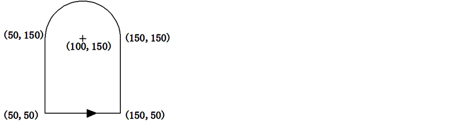
According to 3.1, the difficulty of graphic element analysis is arc. Although the information in DXF file can confirm geometry feature, for the track sequencing, the start and end point coordinates are needed; and for the motion controller programs, it also need to change the format for direct connection. By four elements of center, radius, start angle and end angle as well as simple trigonometric function calculation, the start and end point position as well as the rotation angle of the arc can be determined. For example, if center of the arc is o(x0, y0), radius is r, start angle is θ (0 < θ < 90˚) and end angle is δ (0 < θ < 90˚), according to the parametric equation of the circle, the start point a(x1, y1), end point b(x2, y2), and rotation angle ε can be calculated using Equation (1) to Equation (3):
 (1)
(1)
 (2)
(2)
 (3)
(3)
Parts of the C# program of arc analysis are as follows:
for (h = 0; h < shu; h++)
{ if(s[i,0] == 3)
{ ...
if (s[h, 11] > 180 && s[h, 11] < 270)
{
s[h, 1] = s[h, 7] - Math.Cos(s[h, 11] - 180) * s[h, 10];
s[h, 2] = s[h, 8] - Math.Sin(s[h, 11] - 180) * s[h, 10];
……
5. Development of Open CNC Engraving Machine System
The hardware of the open CNC engraving machine system includes a motion controller and an upper computer (PC). The real-time control of the CNC engraving machine body is done by the motion controller. The main task of the motion controller is servo motor control and IO logic control. The PC runs The DXF analysis algorithm, Human-Machine Interface (HMI) and sends the motion control instructions got from the DXF analysis algorithm to the motion controller, so the engraving machine can be controlled.
The software of the system includes PC program and motion controller program.
5.1. PC Program
The PC program includes HMI and DXF analysis program running in the background. DXF analysis program are mainly programmed based on DXF analysis principles and methods on 3. The HMI developed by C# is shown in Figure 3.

Figure 3. Human-machine interface.
5.2. Program Design of Motion Controller
In this design, the subprograms of linear and circular interpolation are programmed in GALIL motion controller. According to the results of DXF analysis in PC, call different subprogram in proper order and assign variable, the continuous tracking trajectory can be realized. The linear interpolation program of GALIL motion controller is as follows:
#LINEAR //the subprogram name of linear interpolation
MT 2, 2 // specify the type of motor
VMAB // specify the motion plane
VS 5000 //specify the vector speed of 5000 counts/sec
VA 100000 // specify the vector acceleration of 100000 counts
VD 100000 // specify the vector deceleration of 100000 counts
VP X, Y // specifies the coordinates of the end points (X,Y are variables which is identified from the DXF file.)
VE // specify the end of the coordinated motion
BGS // motion begin
EN //end of the subprogram
6. Test Running Result
By C#, the authors first finished the DXF file identification as well as the extraction and storage of graphic element information. The graphic element ordering operations were also achieved. At last, the graphics trajectories were generated by calling the bottom GALIL software instructions and achieved motion tacking. The test was carried out on a three axes motion experiment platform which is shown in Figure 4, the carving cutter was replaced with pen. Pen was fixed on the experiment platform.
The test used a trajectory graph drawn by AutoCAD which is shown in Figure 5(a). With the author’s method, the graph was identified and the results were stored in a 2D array [i, j] which is defined in Table 2. The result is shown in Table 3. Table 3 indicates that the identify result is consistent with the CAD graph. Figure 5(b) is the

Figure 4. Experiment platform.

 (a) (b) (c)
Figure 5. Test result.
Table 3. The identify result of CAD graph.
trajectory graph which is drawn by the three axes motion experiment platform according to the identify result. Figure 5(c) shows the motion process. The final result shows that the developed open CNC engraving machine system can accurately complete the identification of DXF file, and the walk path is consistent with the CAD file.
References
- Omirou Sotiris, L. and Barouni Antigoni, K. (2005) Integration of New Programming Capabilities into a CNC Milling System. Robotics and Computer-Integrated Manufacturing, 21, 518-527. http://dx.doi.org/10.1016/j.rcim.2004.10.002
- Kovacic, M., Brezocnik, M., Pahole, I., Balic, J. and Kecelj, B. (2005) Evolutionary Programming of CNC Machines. Journal of Materials Processing Technology, 164-165, 1379-1387. http://dx.doi.org/10.1016/j.jmatprotec.2005.02.047
- Zhai, R. and Zhang, L. (2011) Reading Frame Design Based on the DXF File Format. Fujian Computer, 4, 107-109.
- Huang, J.Q. and Yuan, Q. (2012) Automatic Input and Identification for Stamping Graph Based on AutoCAD. Machinery Design & Manufacture, 2, 82-84.
- Bai, X.C. and Chen, Y.M. (2010) Automatic Programming of Bridge Cutting Machine Based on the DXF File. Equipment Manufacturing Technology, 2, 110-112.