Journal of Power and Energy Engineering
Vol.05 No.05(2017), Article ID:76478,12 pages
10.4236/jpee.2017.55003
Modeling and Simulation of a Hybrid Energy Storage System for Residential Grid-Tied Solar Microgrid Systems
Abdrahamane Traore1, Allan Taylor2, M. A. Zohdy1, F. Z. Peng2
1Department of Electrical and Computer Engineering, Oakland University, Rochester, MI, USA
2Department of Electrical and Computer Engineering, Michigan State University, East Lansing, MI, USA

Copyright © 2017 by authors and Scientific Research Publishing Inc.
This work is licensed under the Creative Commons Attribution International License (CC BY 4.0).
http://creativecommons.org/licenses/by/4.0/


Received: April 4, 2017; Accepted: May 23, 2017; Published: May 26, 2017
ABSTRACT
Present-day power conversion and conditioning systems focus on transferring energy from a single type of power source into a single type of load or energy storage system (ESS). While these systems can be optimized within their specific topology (e.g. MPPT for solar applications and BMS for batteries), the topologies are not easily adapted to accept a wide range of power flow operating conditions. With a hybrid approach to energy storage and power flow, a system can be designed to operate at its most advantageous point, given the operating conditions. Based on the load demand, the system can select the optimal power source and ESS. This paper will investigate the feasibility of combining two types of power sources (main utility grid and photovoltaics (PV)) along with two types of ESS (ultra-capacitors and batteries). The simulation results will show the impact of a hybrid ESS on a grid-tied residential microgrid system performance under various operating scenarios.
Keywords:
Microgrid, Solar, Hybrid Energy Storage Systems, Grid-Tied, Renewable Energy, System Modeling, Batteries

1. Introduction
In developed regions, which make use of large energy distribution infrastructures (such as the U.S.), the energy demands fluctuate throughout the day. In most residential areas, the demand on the power utility grid follows a trend resembling a double-bell curve, with high demands early in the morning and late in the evening. A typical daily residential energy demand curve is presented in Figure 1. Existing residential energy profiles vary from household to household according to the way each household operates its loads. A load is defined as something that uses electrical power to perform a task. Some common U.S. household loads are: HVAC units, refrigerators, TVs, microwave ovens, lights, fans, modems, coffee makers, computers, phones, etc.
In areas where the grid power is not reliable, an ESS provides continued power, grid stability and frequency regulation. Currently, the main types of ESS systems deployed in the US are intended for natural disaster/emergency situations or transient/remote operation situations. The ESSs used in these scenarios are typically gasoline or diesel electric generators. In recent days, however, some US states (such as Hawaii and California) are beginning to move towards large-scale battery installations for grid/renewable energy storage. While battery storage alone may be sufficient for a large-scale energy system, the focus of this paper will be on smaller-scale residential systems, where hybrid energy storage is more applicable. Researchers around the world are working on examining the pollution emissions and environmental impacts in the supply chain of renewable energy components (i.e. electrical power conditioning and energy storage systems components). A study led by Argonne National Laboratory [1] found that the manufacturing process of Lithium-Ion batteries was somewhat energy intensive (roughly 120 MJ/kg of battery material), this did not generate substantial CO2 emissions. To compare the microgrid pollution to that of the traditional power generation technology, an aggregated sum of pollution emissions from the supply chain of all the components in the microgrid must be examined. However, this pollution study is beyond the scope of this paper.

Figure 1. Typical household power demand vs. hours of the day.
1.1. The Utility Grid
The U.S. electrical network is made up of many utilities generating electricity (mainly from burning fossil fuels) and distributes this electricity to consumers over long distances. This network of utilities is known as the “utility grid” or “grid”. The utility grid provides single-phase power for small loads and three- phase power for larger loads (e.g. an electric stove). In areas where the grid is reliable, grid power is available throughout the day to support the daily energy consumption. Utilities companies have a rate structure (depending on the states they operate in) they use to bill consumer energy usage.
1.2. Grid-Tied PV Systems
A grid-tied photovoltaic (PV) system can be either commercial (utility-scale PV) or residential (e.g. roof-top PV). This paper will only cover residential grid-tied PV systems. Figure 2 shows a typical daily solar power profile, with high power absorption in the middle of the day. As mentioned earlier in this chapter, a typical residential power demand is high early in the morning and late at night. Consequently, the excess power from the sun during the day can be fed back to the grid.
Here, we can consider the grid as a way to store energy when the solar power exceeds the household demand and can provide power when the household demand is high.
1.3. Grid-Tied PV Systems with ESS
A grid-tied PV system with an energy storage system (ESS) is necessary in areas where the grid power is not reliable. The grid generates energy mainly through

Figure 2. Typical solar power absorption vs. hours of the day.
the use of large electric generators powered by steam which is heated by coal, natural gas, or nuclear fission. The grid can provide energy at all hours of the day, but due to the typical work schedule in today’s US society, the grid experiences its highest demands and stress during the early morning and mid-even- ing times for residential applications. Meanwhile, solar panels convert light energy (photons) from the sun into electricity through the photovoltaic effect within the Silicon junctions of the panel. The solar irradiance peaks during the middle of the day and is unable to supply the heavy demand during the peaking hours. Energy storage is needed to evenly distribute the energy coming from these sources. In the event of a utility grid failure, the ESS will provide back-up electricity to power the loads. An ESS in a grid-tied PV microgrid is typically used for emergency back-up or peak-load shifting (reducing energy load by shifting it from peak to off-peak hours). An example of peak-load shifting will be presented later in this paper.
1.4. Challenges with Existing Technologies
Microgrid technologies (which are localized groupings of intelligently controlled sources and loads) have many challenges, ranging from grid stability to fuel supply disruptions. In [2] , the authors present some technical challenges dealing with voltage and frequency control, islanding and protection of microgrids. However, the biggest challenges today lie in energy storage technologies. While batteries are a typical energy storage solution in microgrid applications, their excepted life is compromised when they are supporting loads with high power pulses for short periods of time. Batteries store electrical energy through the che- mical interactions with metallic conductors and ions moving through an electrolyte. While the energy density of batteries can be quite high, usually the energy transfer rate (the power) is limited by the flow of ions in the battery cell. Additionally, the charge/discharge rate, depth of charge/discharge, and temperature must be monitored & controlled to avoid damage to the battery. In contrast, an ultra-capacitor stores electrical energy in the electric field created between a porous Carbon electrode and ions in a solution. In this case, the energy transfer rate is much higher (since we are not limited by a chemical reaction), but the energy density is lower. Charge levels of super-capacitors must also be monitored to prevent over-charging. Combining these two technologies into a hybrid system can alleviate the energy/power limitations of both systems. Therefore, offsetting the cycling component of battery power is known to facilitate increa- sed operational life, reduced current rates and lower overall thermal burden [3] .
1.5. Proposed Hybrid Concept
In this paper, we discuss a method for modeling a hybrid battery/ultra-capacitor energy storage system as shown in Figure 3. Details about the modeling will be presented in the next chapter. Chapter 3 discusses the simulation parameters used and the simulated results. Chapter 4 lists the conclusions of this paper. This hybrid ESS will allow the system to be more efficient in capturing the available PV power and discharge according to the type of load. Through sensing of the load power, the ESS can deliver an appropriate output power to help reduce the burden on the utility grid.
2. Phasor Analysis and Modeling of System Components
2.1. Modeling
To model the grid in Simulink, the Simscape Power Electronics Toolbox was used. A small neighborhood model (consisting of a few homes) was constructed and connected to a 120 V split-single-phase step-down substation transformer. Table 1 shows the parameters used for the source and transformer simulation in this paper. For the solar PV source power and household demand power, real field data was acquired from ‘Pecan Street Incorporated’, a non-profit research institute headquartered at the University of Texas at Austin. Pican Street Inc. is a provider of consumer energy consumption data for use in residential solar microgrid research [3] . The generic battery model in MATLAB/Simulink [4] provides a dynamic model for simulation of different types of rechargeable batteries. The equivalent circuit of the battery is shown in Figure 4. With selected parameters, the discharge and charge modes of a lead-acid battery are modeled as follows [5] :

Figure 3. Hybrid energy storage system (ESS) for microgrid applications.

Table 1. Parameters of microgrid split-single-phase transformer.
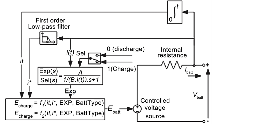
Figure 4. Generic battery model in MATLAB/Simulink [5] .
Discharge model (i* > 0)
 (1)
(1)
Charge model (i* < 0)
 (2)
(2)
where E0 is constant voltage (V), Exp(s), exponential zone dynamics (V), Sel(s), battery mode (0 for discharge, 1 for charge), K, polarization constant (Ah−1) or polarization resistance (Ohms), i*, low frequency current dynamics (A), i, battery current (A), it, extracted capacity (Ah), Q, maximum battery capacity (Ah) and B, exponential capacity (Ah−1).
For modeling of the ESS, batteries can typically support high-energy loads but at low power. On the other hand, ultra-capacitors can handle additional power demands from high-current loads but have low energy storage capability. In this paper, the energy limitations were modeled using an integration of the power with saturation limits. The lower limit can be set to zero to indicate an empty system and the upper limit designates the maximum capacity of the system. If the lower saturation limit is reached, the allowed output power will become zero. If the upper limit is reached, the allowed input power will be zero.
The ESS power limitations are modeled using a simple dynamic equation together with a numerical saturation having a fixed minimum and maximum value. The battery storage system’s power reference is controlled using a low-pass filtered version of the household power demand. Conversely, the ultra-capaci- tor’s power reference control signal is the high-pass-filtered version of the hou- sehold power demand. The Simulink models of the two ESS systems are presen- ted in Figure 5. The transfer functions of these two filters are given as simple first-order filters, described in as follows:
 (a)
(a) (b)
(b)
Figure 5. Simulink modeling of (a) battery and (b) ultra-capacitor storage systems.
 (3)
(3)
 (4)
(4)
where HLP describes the low-pass filter used for the battery power reference, HHP describes the high-pass filter used for the ultra-capacitor power reference, and ωc is the cutoff frequency of the filters. The cutoff frequency for both filters was set to 0.01 Hz.
2.2. Microgrid Topologies
A typical microgrid system can be either AC or DC-coupled, often referred to as an AC microgrid or DC microgrid, respectively. Both AC and DC microgrids have their pros and cons depending on applications [6] . A system-level analysis helps determine which topology is advantageous for a specific application. To perform such analysis, one must consider the type of power generation, size of the microgrid and type of loads available [7] .
In an AC microgrid, shown in Figure 6, the DC output from the solar PV is directly inverted into an AC voltage to power AC loads. This is ideal for “grid-direct” systems, taking DC power from the solar panels to an existing home via the AC wiring to the grid. In AC microgrids, a grid-tied PV inverter can allow the PV to first power the loads then charge the ESS, and feed any excess power back to the grid. From Figure 6, one can observe that the DC power from the PV is inverted into AC by the PV-inverter and can then be either consumed by the load or rectified to DC by the inverter/charger to charge the ESS. Alternatively, the stored ESS voltage can be inverted back to AC to power the AC loads.
In a DC microgrid, shown in Figure 7, the PV array and the ESS are paired via a DC/DC charge controller. The DC microgrid is more efficient [8] at storing solar energy as it takes the DC power from the PV directly into the ESS rather than going from PV (DC) to the grid/load wiring (AC) and then to the ESS (DC). This removes an extrapower conversion step (resulting in a small efficiency gain) compared to an AC microgrid.
Peak-shifting, as shown in Figure 8, is the ability of the system to store power during valley time in a load profile and use that energy to reduce or eliminate the peak demands.

Figure 6. Topology of a grid-tied solar AC microgrid with ESS.

Figure 7. Topology of a grid-tied solar DC microgrid with ESS.
3. Simulation Results of Various Source/Load Scenarios
To verify the analysis of the proposed ESS control strategies, a solar microgrid system was simulated, having a daily household power demand as described by Figure 1 and a 2kW-peak solar installation described by Figure 2. The simulation model was developed using MATLAB/Simulink. The key parameters of the system are listed in Table 2.
To see the effects of the ESS on the demanded household power, three different simulation scenarios were created:
Case 1: A house with solar, plus battery storage,
Case 2: A house with solar, plus ultra-capacitor storage,
Case 3: A house with solar, plus a hybrid ESS using a battery and an ultra-ca- pacitor.
In each case, the original household demand power is compared with the demand presented to the grid, which is the combination of the household power, solar power, and the compensated power of the ESS.
3.1. Case 1
The simulation output of the first case (having only battery storage) can be seen in Figure 9. The battery is effective at smoothening the overall power demands from the house over the course of the day, but the high-frequency transient loads are not effectively canceled out, due to the limited response speed of the battery control.
We can also observe from Figure 9 the peak-shaving behavior of the battery control. From 0700 hours to 1700 hours, the battery will charge/discharge from/ to the grid to prepare for the peak-power hours during the day. Reducing the

Figure 8. Peak-shifting load curves vs. time of day.
Table 2. Simulation parameters of microgrid solar system with energy storage.

Figure 9. Household demand power using only battery storage.
power demands during the peak hours helps to lower the utility costs to the consumer. The direction of the power flow will depend on the size of the solar installation and the household-in this simulation, we might conclude that the solar installation is oversized, as the battery is discharging to the grid during the night-hours.
3.2. Case 2
The simulation outputs for the second scenario (using only ultra-capacitors) can be seen in Figure 10. We can see in this case that the abrupt changes in power demand have been smoothened by the ultra-capacitor. Most of these abrupt changes in power demand are caused by switching loads in the house and the transient solar power output (due to clouds passing over the array). As seen in the figure, however, the ultra-capacitor is unable to shift the average demand away from the peak-hours of the night, due to the limited storage capability of the capacitors and the control method being used.
3.3. Case 3
Lastly in Figure 11, we show for the same household and solar array output, the effects of the combined hybrid energy storage system. The combined ESS topology yields the smallest magnitude power demands presented to the grid. Furthermore, the demand during peak hours has been significantly reduced, similar to the “battery-only” scenario, by employing the peak-shifting technique.
4. Conclusion
This paper examined how hybrid ESS would work out in different residential grid-tied microgrid scenarios. A trade-off between an AC versus a DC microgrid

Figure 10. Household demand power using only ultra-capacitor storage.

Figure 11. Household demand power using hybrid storage (battery and ultra-capacitor).
was presented. Emphasis was placed on system level performance based on real residential field data from [3] . From the simulation results, one can see that an optimal, sustainable microgrid system requires a hybrid energy storage system to meet the demands of a mixed load scenario. More advanced control and optimization techniques, such as the ones described in [9] [10] , can also be considered for planning, sizing and operating microgrids. The results can be used for planning and optimal sizing of an off-grid rural power system. This research also provides a framework for planning large scale micro grid systems as well. Further work should be performed to determine an optimal battery/ultra-capacitor ratio for sizing such hybrid ESS. The National Renewable Energy Laboratory (NREL) published a technical report about standards for renewable energy systems (including microgrids) integration with the grid [11] . The report mentions some standards for connection, and frequency; and it states that other standards are still being developed or modified to accommodate islanding and other modes. These standards and regulations are evolving as microgrids are becoming more and more popular in the US.
Cite this paper
Traore, A., Taylor, A., Zohdy, M.A. and Peng, F.Z. (2017) Modeling and Simulation of a Hybrid Energy Storage System for Residential Grid-Tied Solar Microgrid Systems. Journal of Power and Energy Engineering, 5, 28-39. https://doi.org/10.4236/jpee.2017.55003
References
- 1. Gaines, L. and Dunn, J. (2015) Lithium-Ion Battery Production and Recycling Materials Issues. VTO Annual Merit Review, Argonne National Laboratory, Project ID: ES229.
- 2. Salam, A.A., Mohamed, A. and Hannan, M.A. (2008) Technical Challenges of Microgrid. ARPN Journal of Engineering and Applied Sciences, 3, 64-69.
- 3. Miller, J.M. (2010) The Role and Future of Power Electronics in Energy Storage Systems. Presented 26 April 2010, Kettering University.
- 4. Dataport (2016) A Universe of Energy Data, Available Around the World. Retrieved 12 March 2016.
https://dataport.cloud/ - 5. MathWorks (2016) Documentation about the Battery.
http://www.mathworks.com/help/physmod/sps/powersys/ref/battery.html - 6. SMA. Decentral Energy Concepts with Sunny Island. SMA Solar Academy, Island-EN112813.
- 7. Inam, W., Strawser, D., Afridi, K.K., Ram, R.J. and Perreault, D.J. (2015) Architecture and System Analysis of Microgrids with Peer-to-Peer Electricity Sharing to Create a Marketplace Which Enables Energy Access. 2015 9th International Conference on Power Electronics and ECCE Asia (ICPE-ECCE Asia), Seoul, 1-5 June 2015, 464-469.
https://doi.org/10.1109/ICPE.2015.7167826 - 8. Lotfi, H. and Khodaei, A. (2015) AC versus DC Microgrid Planning. IEEE Transactions on Smart Grid, 8, 296-304.
- 9. Zohdy, M.A. (1987) A Robust Optimal Model Matching Control. IEEE Transactions on Automatic Control, 32, 410-414.
https://doi.org/10.1109/TAC.1987.1104617 - 10. Gao, D.W. (2015) Energy Storage for Sustainable Microgrid. Elsevier, Amsterdam.
- 11. Thomas, B. (2014) IEEE 1547 and 2030 Standards for Distributed Energy Resources Interconnection and Interoperability with the Electricity Grid. National Renewable Energy Laboratory Technical Report, NREL/TP-5D00-63157.