Open Journal of Safety Science and Technology
Vol.05 No.04(2015), Article ID:61983,18 pages
10.4236/ojsst.2015.54013
Review on Rockburst Theory and Types of Rock Support in Rockburst Prone Mines
Eugie Kabwe, Yiming Wang
Department of Mining and Mineral Resources Engineering, University of Science and Technology Beijing, Beijing, China

Copyright © 2015 by authors and Scientific Research Publishing Inc.
This work is licensed under the Creative Commons Attribution International License (CC BY).


Received 8 November 2015; accepted 14 December 2015; published 17 December 2015

ABSTRACT
As the depth of mining increases, the occurrence of seismic events is becoming a more common phenomenon causing serious problems regarding to the stability and safety of mines. However, seismicity and the accompanying rockburst phenomena are not a well-defined and well-under- stood in underground excavations in these times. Efforts to clearly explain the mechanisms are underway. This paper is an overview on the mechanism of rockburst and supports applicably in rockburst prone excavations, predicted classification scales for damage on rock surfaces and rock supports. Current design methods for support systems are reviewed, which are mostly dependent on practical approaches and are geared towards static support design. Based on this, the current review focuses on ground supports under dynamic conditions.
Keywords:
Cone Bolts, Jacketted Rock Bolt, Rockburst, Rock Support, Yield-Lok

1. Introduction
The overall stress field attains high values when mining reaches greater depths. This stress is further redistributed due to the activity resulting in excessive stress concentrations in certain sections of the rock mass. Accumulation of stress in the rock leads to destructive stress that causes fracture which can be a seismic source. The passing dynamic stress wave as a result of fracturing in the rock mass is defined as a seismic event. A seismic event can also be a sudden inelastic deformation within a given size of rock [1] [2] . Effectively, a seismic event is the vibration of rock breaking. Seismic events are a normal response of a rockmass to the stress changes caused by the creation of mining excavations. The term seismicity is given various definitions with different authors. One definition can be stated seismicity as the rock mass response to deformation and failure [2] .
2. Rockburst
The rockburst phenomena, came into sight in the early 1900s in the mines of South Africa [3] . Today several deep underground mines in all around the world face the problem of rockbursts. A rockburst is a mining-induced seismic event that affects and cause destruction to excavations in the rock [2] . It is vital to differentiate between seismic event and rockburst. A seismic event does not necessarily cause damage in openings, while a rockburst will, with varying severity of damage. A very good definition of rockburst given by the Canadian Rockburst Research Program is “damage to an excavation that occurs in a sudden or violent manner and is associated with a seismic event” [3] [4] . The role of seismic events in a rockburst phenomenon can be examined as to the actual course of burst; if it’s the seismic event or the stored stress energy in the rock around an excavation released during breaking. A seismic event can be located at a certain distance away from the rockburst location, or can also overlap with the rockburst phenomenon as in the case of strain bursts. Hence the cause of rockbursts can generally be classified as self-initiated and remotely triggered [5] .
Self-initiated rockbursts arise from the stresses close to the boundary of an excavation which exceed the strength of a rock mass and failure can be in unstable manner. The stress redistribution that is the outcome of a nearby mining increases the concentration of the stresses at the spot. Degradation of strength with time and loss of confinement can also deteriorate the capacity of the rock mass. One or all of these conditions lead the strength of the rock mass to be exceeded by the stress and consequently lead to failure. Loss of structural stability, a factor independent of the strength of the rock mass, can also cause a self-initiated rockburst as can be demonstrated in the sudden buckling of column or slab of rock [6] .
Remotely triggered rockbursts are caused by large magnitude seismic events. Remotely triggered rockbursts commonly occur in some hard rock mines, usually after the mine has been significantly mined out and where faults intersect stopes or large mined-out areas and sill pillars. Large vibrations and the accompanying dynamic stresses as a result of incoming seismic waves can lead to both fracturing of the rock mass and structural instability. Furthermore the mining stage can influence the phenomena of rock bursting. In the initial stage of the mine’s life highly localized stress concentrations near drifts that are relatively isolated from each other are the usual causes of the events. In the later life stage of the mine multiple opening and numerous stopes cause additional rockburst mechanisms [6] .
Rock bursts are generally divided into three classifications:
・ Strain bursts: These are caused by high-stress concentrations at the edge of mine openings that exceed the strength of the rock. Events can range from small slivers of rock being ejected from the walls to the collapse of a complete wall as it tries to achieve a more stable shape.
・ Pillar bursts: Severe rock bursts, involving thousands of tons, have been caused by the complete collapse of support pillars. These tend to occur in extensively mined-out areas, and the resulting damage can be severe.
・ Fault slip bursts: Recognized in the 1980s, this type of rock burst occurs when slippage suddenly occurs along a geological weakness plane. This is the same mechanism as for an earthquake.
Damage may occur as rock bulking by fracturing, ejection of rock due to seismic energy, or rockfalls by seismic quaking (Figure 1) [7] . Each mechanism may result in different levels of damage to an excavation and its support system. The damage severity depends on many factors, including:
・ Failure potential near the opening;
・ Support effectiveness;
・ Local rock stiffness;
・ Magnitude of seismically induced stress, rock accelerations, or velocities;
・ Opening geometry, size, and orientation;
・ Geological structure.
Three levels of rock burst damage severity are defined in Figure 1. Damage level determination is usually based on observations of previous damage, where such observations are available, plus analytical methods [8] . Severity levels are summarized in Table 1. Only a limited number of ground support elements are suitable for dynamic loading conditions, and under the most severe conditions even these are restricted by maximum practical support limitations [8] .
3. Rock Reinforcement Systems
The main purpose of rock reinforcement in underground mining is to ensure stability of the rock mass around
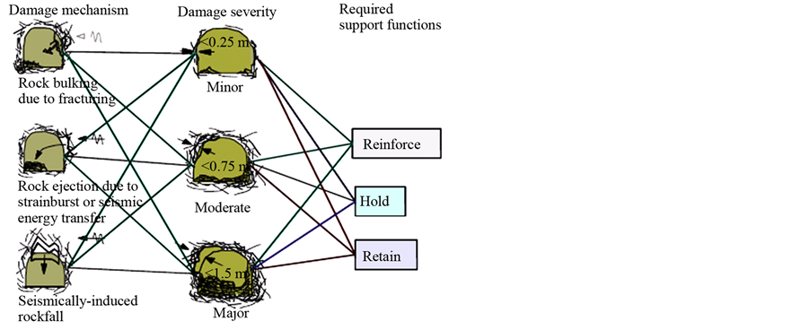
Figure 1. Type of damage mechanism, damage intensity and applicable support functions (After Kaiser et al. (1996)).

Table 1. Rock-burst damage mechanisms and the nature of anticipated damage (After Kaiser et al. (1996)).
excavation openings while maintaining access to the mine, allowing the rock mass to support itself with its natural strength, while keeping the intended functionalities.
Support systems may be classified into two broad categories: internal and external, which can be either active or passive. A support becomes active when stresses are induced in it at the time of installation. Therefore, such supports reinforce the rock mass structure by exerting an “induced” stress on the ground immediately after its installation [8] . The common examples are pre tensioned rock bolts, hydraulic props and power-driven supports for long wall faces. Active supports are applied in situations where an excavation is believed to cause excessive deformation in the ground [9] . An example of this situation is separation of rock wedges from the rock mass. Passive supports do not reinforce the rock mass immediately after installation, but their effect is seen as subsequent mining activities take place. Examples of passive supports are steel arches, timber sets, composite packs and un-tensioned bolts. External supports are generally of the passive type, they are placed around the boundary of the excavation to help restrain the movement of the rock walls and avoid the failure of rock mass. Steel arches, wooden cribs and fiber reinforced shotcrete are some types of external supports. Backfill is another common type of external, passive support used in hard rock mining. Internal supports continue to see technological developments in the mining industry. The basic mechanism of internal support is to bound rocks together to maintain the overall stability of the rock mass around an excavation. Internal supports which are pre-tensioned at the time of installation are considered to be of the active type. Swellex, Split Sets, grouted bars and mechanical anchors are some of the common examples of internal supports. Rock bolts are most preferred during support installations in underground excavations than other types of supports because they provide unbarred excavation openings and have minimum repairs and set up, they require less storage space, they are very easy to install and require less installation time.
Instability of the rock mass is usually triggered by the mining activities, alteration of the in-situ stresses, causing either extreme high stresses that are way above the rock strength, this result in shear failure or relatively extensive spalling or low stresses causing progressive failure along planes of low strength. In cases of increasing depth or at later age of the mine, seismicity and rockbursts arise due to slippage on natural or mining-induced planes of weakness and fracture of the intact rock itself (strain burst), usually close to excavation boundaries [5] . For a successful support and reinforcement systems, the maximum effect is achieved by the interaction between the bolt and shotcrete, thus retaining and holding. (Figure 2) shows the concept between rock mass, and the reinforcement components: bolts, mesh and shotcrete.
The five most important characteristics of support in burst-prone grounds are: 1) Peak load capacity of the support; 2) Displacement at peak capacity; 3) Ultimate load bearing capacity or yield support; 4) Ultimate displacement capacity or stretch limit; 5) Energy dissipation capacity of support. The choice of a support system will depend on the geo-mechanical conditions, stress field, geology, the expected loading and nature of the damage.
3.1. Dynamic Supports for Burst Prone Ground
Reinforcing mechanisms generally restrict and control the bulking of the rock mass. Typically, reinforcing elements like grouted rebars act as stiff support elements, however split set bolts, yielding Swellex or Cone bolts [10] , act as ductile or yielding elements under high stress conditions. The holding function of supports is aimed to hold the retaining elements of the system and loose rock to stable ground.
Dynamic support design effectively implies rock-burst-resistant support design and is a function of the size of the seismic event and the location of the event hypocenter relative to the mine infrastructure in question. Local site factors such as the orientation of the infrastructure can also play a significant role in support and ground performance. Support ductility is required to achieve displacement capacity and energy absorption capacity [8] .
The main issue with underground excavation is the stabilization of the rock around excavations at depth. The main difference between deep rock and surface rock is the increment of the in situ stresses. Significantly this increase in the rock stresses, result in rockburst occurrence in hard rocks, large squeezing deformations in soft and weak rocks. From observation in most underground mines, rockburst phenomena begins at depths from 600 m to 800 m and more pronounced below 1000 m. Most metal mines in Sweden, Canada, Australia and South Africa, at the moment mining operations are at depths between 1000 m and 3000 m. At such depths, conventional support devices [11] [12] fail to cope with the severe rock conditions.
Conventional rock bolts are categorised in three types looking at their anchoring mechanisms: 1) Two-point fixed mechanical bolts; 2) Fully encapsulated rebar bolts; 3) Frictional bolts. Fully encapsulated rebar bolts are fused to the grout/rock lengthwise with a link between the bolt ribs and the grout. Rebar has a high load-bearing capacity, though, rebar cannot accommodate large rock dilations, would only endure a deformation of 2 - 3 cm when exposed to a fracture this indicates that it’s a tough but rigid rock bolt (Figure 3). Interaction of frictional rock bolts with the rock is through friction amid the hole wall and the cylinder-shaped surface of the bolt.

Figure 2. Interaction of reinforcement components (McCreath and Kaiser, 1992).
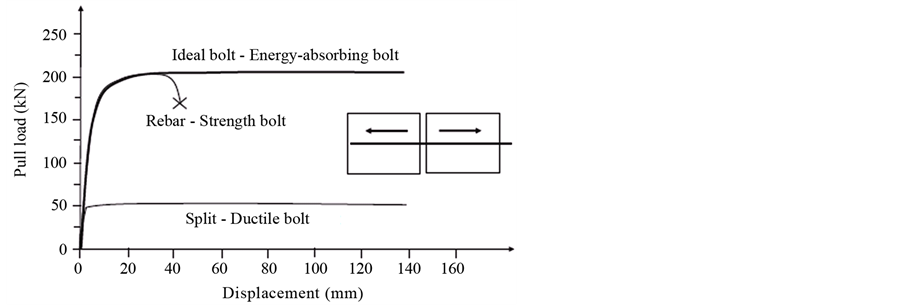
Figure 3. Ideal bolt properties in relative to other bolts (After Li CC (2013)).
The bolts can endure large rock deformations with a low load-bearing capacity. A standard Split Set bolt cannot carry a load greater than 50 kN (Figure 3). A perfect support scheme needs to be tough but rigid like are bar and endure deformation like a Split Set bolt (Figure 3), with the ability to handle load similar to the strength of the rock bolt material [12] .
It is not suitable to use rebar bolts as rock reinforcement devices at depths with high in situ rock stresses. When used with weak and soft rocks, it is often observed that either the face plate of the rebar is greatly loaded, or the thread of the bolt is pulled to failure [12] [13] . In the case of hard rocks, the rock spalls and peels behind the bolt plate, leaving a short part of an extruding bolt out of the rock surface. In Kiirunavaara mine in Sweden, old rebar bolts are occasionally visible on the work faces of successive cut slices. It is seen that some of those bolts fail all because of minor shear and initial movement at rock fractures [14] .
The untimely failure of the rebar bolts (Figure 3), indicates that a rebar is too stiff to withstand rock dilations in high stress rock masses [15] . To withstand large rock dilations, Split Sets are used as reinforcement devices in many deep mines. They are capable of enduring large rock deformations, but their load-bearing capacity is very low. Both rebar and Split Sets are low energy-absorbing devices. Ortlepp pointed out that support devices applicable in deep mines should be able to handle high loads and also withstand large deformations, in that they should be able to absorb a large amount of energy prior to failure [12] [16] . The first energy-absorbing device designed to counteract rock burst problems is the cone bolt [12] [17] .
3.2. Ideal Bolt
Rock bolts can be strength bolt, ductile bolt, or an energy-absorbing bolt. Strength bolts are those that provide a support load equal or close to the intrinsic strength of the bolt material. Ductile bolts are able to accommodate large rock deformations. Energy-absorbing bolts are characterized by their high load capacity and also their large deformation capacity [12] . The installed rock support system must be able to absorb dynamic energy while at the same time be able accommodate large rock deformation due to rock failure.
Strategically, installed support system is focused on the control of rock performance after failure, not on the prevention of rock failure occurrence [18] . In fact, it is actually un-economical to prevent rock damage from occurring by the increase in rock support capacity. In rock damage control, the support behaviour must be essentially altered to allow for yielding. This section reviews the current support applicable in burst prone ground that have energy absorption or yielding capacity. Enforcement of stability for large rock blocks, and the holding together of weak lamented rock are achieved by rock bolts of the correct dimension. Widespread research and advance work on yielding rock support has been conducted, energy-absorbing bolts have been successively developed and applied. Currently, dozens of energy-absorbing bolt types and their yielding mechanism can be illustrated as structural components sliding and steel deformation (Figure 4) [18] .
3.2.1. Swellex Rock Bolt
Swellex is a friction bolt; the dowel varies up to a length of 12 m (Figure 5). The Swellex Mn2 4 is a 3 m long and a 25 mm diameter tube before folded during manufacturing. Pm24C Swellex bolts can be used to provide

Figure 4. Illustration of Yielding mechanism of a rock bolt (After Wang et al. (2013)).

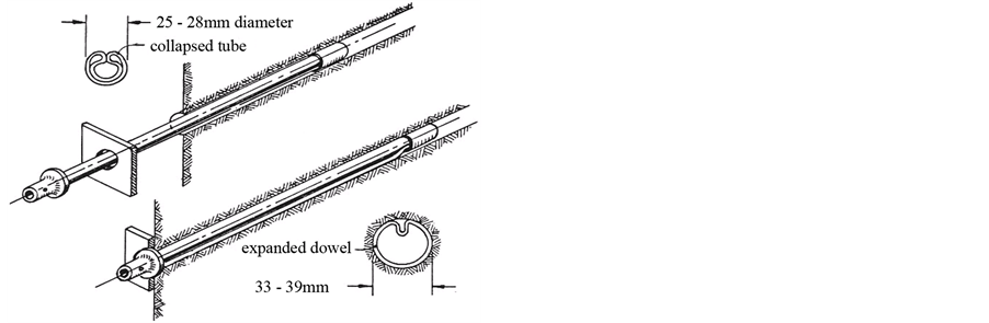
Figure 5. Friction anchored rockbolt―Swellex.
deep tendon support under dynamic loading (Table 2). When inserted into a drill hole (32 - 39 mm) no extensive driving force is required. It has expansion capability of 42 mm when activated by injection of high water pressure, causing a tight contact with the drillhole walls after the inflation. The concept of the bolt entails that the rock is secured by immediate and full support action. The moment the bolt is expanded in the hole, it interacts with the rock to maintain its integrity. The excellence of the bolt installation is confirmed when the pump stops, and is independent of rock mass conditions or operator experience [19] . The Swellex rockbolts are intended to enhance the efficiency of each bolt, so that the bolting operation ties with the required safety levels as intended [20] .
3.2.2. Roofex
Roofex is made up of a steel bar encased in a smooth plastic cover fixed inside the borehole with cement or resin grout (Figure 6). The bolt has an energy absorber, it works like a sliding element over the steel bar. Enabling the bolt to extend outwards during sudden movements from rock bursts while at the same time providing constant load capacity (Figure 7). This capability makes the Roofex rock bolt especially appropriate for developing new underground excavations in rock burst prone areas [20] . The bolt can be made in different lengths usually used in mining, and capacity of displacement can be designated at the time of bolt manufacturing.
3.2.3. Cone Bolts
The cone bolt is made up of a smooth steel bar coated with a thin layer of waxy lubricating material, so that it easily detaches from the grout under a tensile load, the bar has a flattened conical bell-shaped forged section at one end (Figure 8). The bolt is entirely encapsulated with cement grout or resin in a borehole. Installed in a specifically formulated Coneloc or Fasloc resin, clearly mixed by the resin mixing blade. A plastic sleeve is installed over the shaft of the bolt to debond the resin from the bar, thus allowing the cone to yield or plough


Figure 6. Roofex rock bolt.
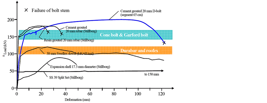
Figure 7. Displacement characteristics of rock bolts (after Li, 2013).

Figure 8. Cone bolt.
through the resin. Cone bolts show high-ductility and energy absorption characteristics. Cone bolts should provide high-shear resistance [8] .
A pull load is induced in the bolt shank when the rock mass dilates in between the cone and the bolt plate. The bolt has been designed in that the conical end section works through the grout material when exposed to a pull load exceeding a predefined value. This enables the bolt to absorb energy from the rock, initially it was designed for use with cement grout later adapted to resin grout [12] .
3.2.4. Modified Cone Bolt
The Modified Cone Bolt cone bolt is basically a smooth bar with a threaded section at one end, forged cone and mixing blade at the other end which works as a resin mixer (Figure 9). These bolts are usually applied in many
Table 2. Swellex properties.

Figure 9. Modified cone bolt.
burst-prone mines especially in Canada as the main dynamic rock support systems. Ground observations carried out in mines revealed susceptibilities in the exterior anchoring point of the bolt especially at the bolt plate. The anchoring may be lost if the rock fractures behind the plate and falls down [21] , this causes the bolt to completely lose its reinforcement ability. Observed that the resin takes time and at times fails to harden, indicating that the cone bolt mixing quality of resin is not always definite and to the standard [22] .
3.2.5. D-Bolts
The D-bolt was developed to stabilize both burst-prone and squeezing rock conditions that are a major factor in underground excavation. The bolt is made up of a smooth steel bar with anchored sections along its length. These can firmly be fixed within a borehole with the aid of cement grout or resin, the smooth segments between the anchors may easily bend in reaction to rock stretching (Figure 10). Reinforcement performance of the other segments can never be affected if one of the other segment fails. The bolt is designed to completely utilize the strength and the deformation capability of the bolt material lengthwise. The bolt has large load-bearing and deformation capacities. Through static pull trials and dynamic drop trials it was seen that the bolt extent lengthens from about 14% - 20% at a load equal to the strength its material, thus absorbing a larger quantity of energy (Figure 11). The impact normal load of a 20 mm D bolt was about 200 - 230 kN, with some percentage of the load transmitted to the bolt plate [12] [23] .
3.2.6. Garford Bolt
The Gar ford dynamic bolt is comprised of a compact steel bar, an anchor and a coarse-threaded steel cover at one end (Figure 12). Its characterised by its anchor this permits the bolt to expanse by a great extent when the rock dilates. Varden et al. presented some tests and selection of the gar ford dynamic bolt (Figure 13) for use under dynamic conditions and explained that the bolt comprises of a 20 mm mild steel solid bar and a resin mixing device of 350 mm long, 43 mm diameter rough threaded steel cover folded at the end. The dynamic segment is an original sliding anchor mechanism which is constrained on to the bolt beneath the mixing device.

Figure 10. D-bolt.
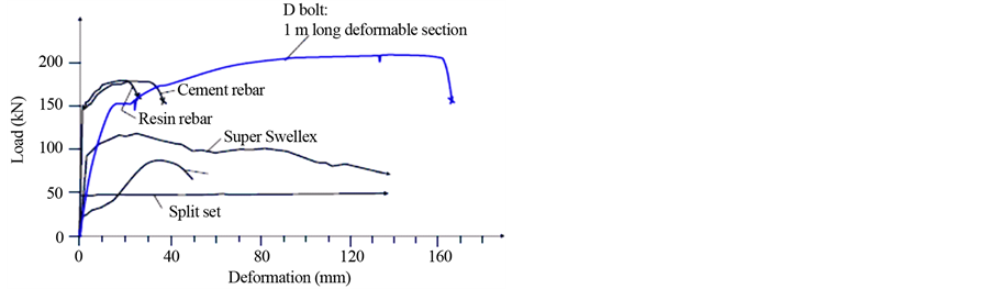
Figure 11. Load-displacement of D bolt under pull loading test.
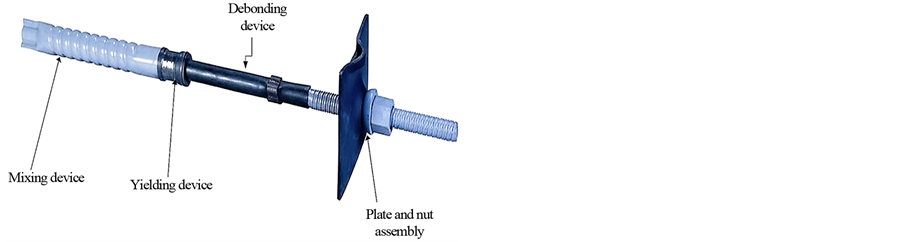
Figure 12. Garford bolt.

Figure 13. Dynamic force displacement curves (After Varden et al. 2008).
The rest of the bolt is enclosed in a polyethylene sheath, this provides a debonding action, which debonds the bolt below the dynamic section. Under a dynamic condition the bolt is pushed through the narrow opening and it stretches [24] .
3.2.7. Dura Bar
This is an energy-absorbing yielding rockbolt. It is anchored at two-points. The inner anchor of the bolt is a crinkled segment of the smooth bolt stem that slips at a predefined pull load. The external anchor is the bolt plate, the rod is bent to form a wave and act as a ductile anchor. The collar end is completed by an eye for cable lacing or a threaded segment for nut and washer (Figure 14). The entire length of the bar is coated with wax excluding the collar end for improved de-bonding. The hole is injected using cement grout the anchor of Dura bar is a creased segment of the bar. During face plate loading, the anchor slips alongside the creased outline in the cement grout at a definite pull load [25] . (Figure 15) shows displacement of the bar under a dynamic test.
3.2.8. Dynatork Bolt
Its Dywidag systems international dynamic bolt, it’s made with a coiled mixing blade to ensure ultimate mixing of DSI resin in the borehole (Figure 16).
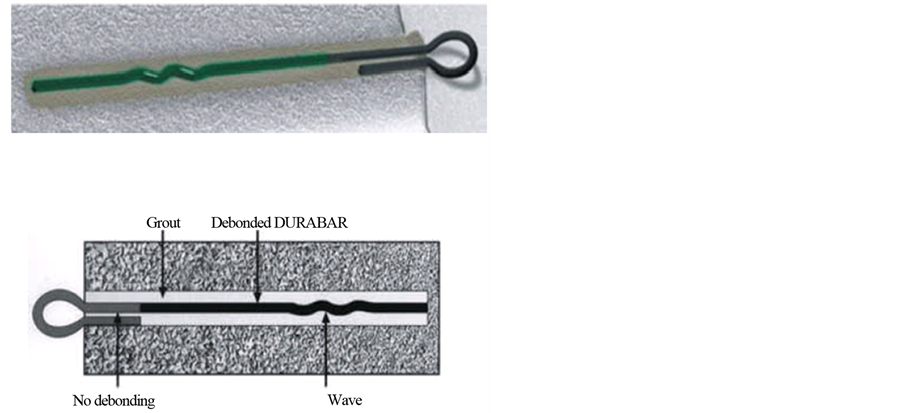
Figure 14. Dura bar.
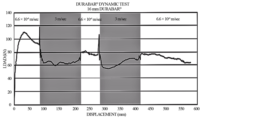
Figure 15. Dynamic test results of DURABAR yieldable bolt (CANMET-MMSL, 2012).

Figure 16. DSI dynamic bolt.
This blade design, according to DSI has a double function, mixing the resin correctly and providing perfect docking for support in static conditions. The bolt is engineered to yield and aid transmission of dynamic load into the resin during rock dilation in rock burst conditions, absorbing the energy through controlled deformation (Figure 17). The energy is expected to be absorbed during the ploughing effect of the cone through the resin [25] .
3.2.9. Split Set Bolts
Comprise of a slotted, hollow highly-strengthened steel tube and faceplate. The bolts are fitted by pushing them into an undersized hole. The circular coil force created by compression of a C-shaped tube delivers frictional anchorage along the complete length of the tube (Figure 18). The toe end of the tube is slanted inward to facilitate quick and easy installation. It can be particularly useful in mild rock-burst conditions where the bolt will slip and not break, when used with wire mesh it will hold shattered rock caused by a mild burst.
These bolts can also be used to pin up mesh in highly fractured and yielded ground prior to the application of shotcrete. Provided the load demand does not exceed capacity, this system can work well for short-term support. However, susceptibility to corrosion rules out this system for most long-term support requirements. The bolts are installed as dowels. Split Set bolt pull-out capacity is rated in metric tons per meter (t/m) and is derived from in-situ pull tests. Nominal pull-out strengths vary from 1 to 2 t/m [8] .
3.2.10. The Yield-Lok
This bolt can be fully or partially grouted with resin or cement mortar. The yielding performance is based on the interactions between the polymer coating, the head and the grouting media (Figure 19). The angled head of the polymer coating helps to scrap resin cartridge packing when the bolt is inserted into the resin and this improves anchorage. Mixing of the resin is enabled by deformations on polymer coating similar to rebar, thus the bolt can be fully inserted without rotation, and then spun afterwards to mix the resin. The Bolt can be constructed in dynamic condition a case of YL-Dynamic Bolt or for specified loads in static condition a case of YL-Static Bolt (Table 3) [25] [26] .
When the rock bolt is tensioned, it immediately provides primary support upon being installed. During static loading conditions, the bolt performance is actually similar to a rebar bolt (Figure 20). The head transmits the effects on the polymer coating during dynamic loading, this brings about restricted compression, thermal softening and flow of the polymer around the upset head, creating a pulling effect. The energy from dynamic loading is absorbed by pulling the upset through the polymer, some of the energy is used up during friction between the smooth bar and the polymer coating [25] .
The feature of yielding elements can be well controlled, ensure the steady performance of the bolt in the full length of polymer coating. The purpose of grouting material is to provide confinement of the polymer coating, instead of working as a yielding element as in the case of cone bolts. It means that if the bolt is completely grouted and confined, the performance of the bolt is not dependent on the grouting material. Since the mechanism of displacement is confined within the polymer, de-bonding agents like grease cannot help achieve the

Figure 17. dynamic laboratory test results of DSI-Dynatork bolt (CANMET-MMSL, 2012).

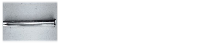
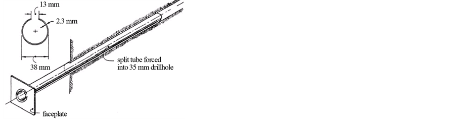
Figure 18. Friction anchor or Split Set.

Figure 19. Yield-Lok.
definite effect and steady performance of the bolt [26] .
3.2.11. Jacketted Rock Bolt
The function of jacketted rock bolts proposed by Chileshe (2015) was to balance the stress and strain, imposed by surrounding rock on grout and/or grouted rock bolts. If the high strain energy in the excavation periphery were to be accommodated over the whole length of a grouted rock bolt to the toe by a load balancing rock bolt, localised strain and stress excess would be mitigated. The low shear stress induced in the minimal strain zone in the deepest toe part of the grouted drill-hole would be increased, while that at the collar of the hole would be reduced. The result would be equitably distributed average shear stress on the rock bolt. The likelihood of grout or grout-rock or grout-bolt or rock bolt failure would be significantly reduced thus increasing the effectiveness
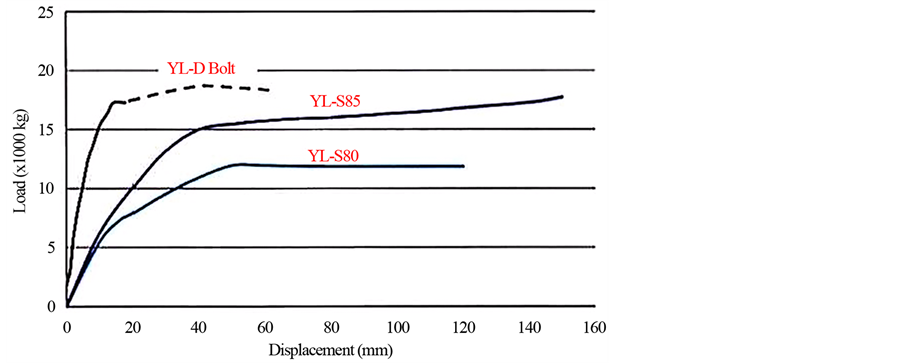
Figure 20. Static test results of Yield-Lok Dynamic and static bolts (CANMET-MMSL, 2012).
Table 3. Yield-Lok Bolt properties.
of the grouted rock bolt. The overall effect of the load-balancing rock bolt would be to increase the effective anchorage length, especially with longer rock bolts [27] .
The bolt is assembled in concentrically tubular steel jackets (Figure 21). Each jacket is 0.6 m to 1.1 m in length, and fitted within each other. The jackets overlap by, say, 0.2 - 0.4 m, thus forming a total length and diameter compatible with a typical rock bolt hole. The tightly or spirally or groove-fitted or lined or indented overlaps would provide friction between jackets and thus transmit energy from one jacket to the other in a frictional balancing system. The capacity to slip is essential. The entire jacketted assembly is grouted into the drill hole or simply in force-fitted direct contact with the rock [27] .
Alternatively, to accommodate extreme cases of gross deformation, such as rock-bursts, the innermost tube can be replaced with a similarly sized solid rod (Figure 22) of a length that allows extension, even protrusion out of the hole [27] .
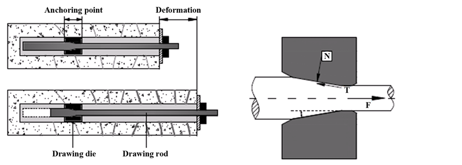
3.2.12. New Yielding Bolt Proposed by (Wang et al., 2012)
This bolt has similar appearance with Roofex, but a different structure of energy-absorber, its more simpler and stable, this increases its resistance. The bolt uses the elastic properties of steel through its operations. The bolt is intended to disperse and control large amount of energy liberated from the rock mass during the process of deformation. The new bolt is made up of a drawing die and drawing rod (Figure 23(a)). The rod is a metal bar with different diameters coated with a thin layer of wax, for easy detachment from the grout under a pull load, the die which also acts as an anchoring point is fixed inside the borehole with cement grout or resin. Operations of the bolt involve the metal being pushed through a die by tension applied at the end of the die. The elastic movement is sorely due to compression, from the metal with the die [15] [23] .
The deformation of the rock induces a tension in the bolt, this causes sliding between the drawing die and rod. When the drawing die orifice diameter gets smaller than the thick end of drawing rod, pressure is induced. When

Figure 21. Jacketted Rock Bolt.
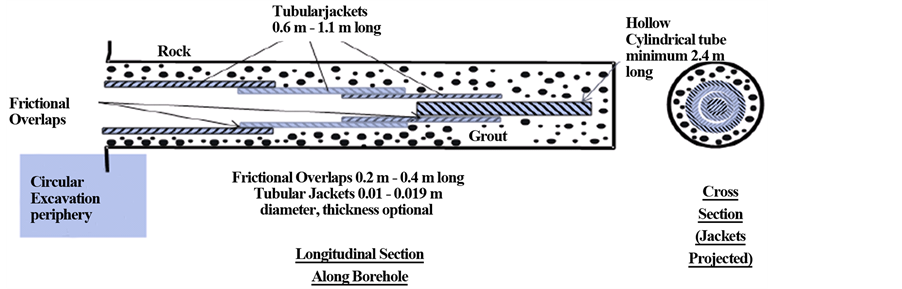
Figure 22. Jacketted Rock Bolt.
 (a) (b)
Figure 23. (a) & (b) Mechanism of the new bolt (After Wang et al. (2012)).
the tension exceeds the defined drawing force, the rod is slowly pulled out (Figure 23(b)). The new bolt is designed to act like a stiff rock reinforcement element until the defined drawing load is exceeded. In the process of drawing, the bolt is capable of absorbing a large amount of energy (Figure 24). In addition to the continuous resistance and the large deformation, the effect of bolt operation is an increase in the rod’s tensile strength. Upon installation, suitable pre-stress is enforced to support the rock mass this enhances the supporting effect considerably [15] [23] .
4. Integrated System Support
To form an integrated system support to be employed in high stress ground conditions rockbolts can be combined
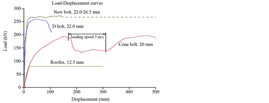
Figure 24. Load versus displacement behaviors of various boltunder pull loading test.
with surface support elements. Installing rock bolts as the only support system reduces the anticipate defficiency of rockburst support. This was observed underground in real rockburst conditions and was also established by a simulated rockburst trial conducted in a South African mine [28] . In the simulated rockburst trial, the support comprised of rebars, mesh, and lacing. Before blasting, mesh and lacing was removed and only there bars were left. Rebars were affected by the dynamic loading but not a single bolt failed due to dynamic loading of maximum peak particle velocity of 3.3 m/s and an ejection velocity of 2.5 m/s which was verified. Milev and Spottiswood (2005) [28] clarified that the cause was due to rapid weakening of peak particle velocity from the surface to the more competent rock mass [18] .
Support displacement capacity is critical in areas of generated dynamic loading [29] . Cablebolts can be effective where fractured ground has relaxed and become vulnerable to vibration. Support loads generated over larger displacements absorb more of the kinetic energy of such a groundmass. Stiff supports will rupture before the mass can be decelerated and stabilized. Cable bolts are rock support elements which can reinforce and hold the rock mass. Cablebolts can survive higher values of ultimate displacement before failure; even though the energy that they could absorb is moderate [8] . It may be advisable to combine long partially bonded cables, with modified geometry or plated end lengths, with closely spaced primary support such as grouted rebar [30] . Under dynamic loading the rebar will maintain a reinforced film at the excavation surface. The large displacement of this film can be accommodated by the cables, maintaining ultimate holding capacity after the disturbance has passed. Without the rebar, the surface skin may loosen and disintegrate, rendering the cable bolts ineffective [31] .
Tannant and Kaiser (1995) [32] describe an innovative support element for support of blocky ground under dynamic loading. A cable is anchored in a borehole using a Swellex friction bolt. A length of cable extends beyond the down hole extent of the Swellex and has an optional button or swage at the end. Even if the Swellex breaks in several places under loading, the cable remains frictionally anchored within the Swellex segments. The load-displacement characteristics are ideal for dynamic conditions; a consistent yield load and a large displacement capacity before rupture [33] .
Wire mesh is used to contain ejected rock and hold back protruding pieces on the excavation surface; it’s usually used in combination with shotcrete. Steel fibre reinforced shotcrete and mesh reinforced shotcrete is extensively used and preferred in underground mining. In poor quality and loose rock masses, where shotcrete to the rock surface is poor due to adhesion, the mesh delivers a significant reinforcement. Thus when stabilizing and building walls for underground fill, weld mesh is applied in the stabilization of the surface [34] .
Steel arches were generally used to support haulages especially in coal mines where they are often essential to withstand large deformations. Deformations can be accommodated by employing yielding arches comprising of elements intended to slip at predetermined loads [35] . Hydraulic props are set with a pre-load to provide active support, The load bearing capacities of individual props may vary from as little as 5 t for a very light prop to more than 100 t for a 0.3-m-diameter prop. Rapid-yielding hydraulic props are widely used to provide concentrated, active support of the hanging wall close to the face. Their rapid-yielding capability allows the energy released by rock bursts to be absorbed rapidly and safely, thereby minimizing the damage caused [35] .
5. Discussion
Charette and Hill (2011) [36] analysed basic static and dynamic loading data of six grouted rock bolt types capable of long term support. They concluded that the rebar and D-Bolt had a higher static load performance, while the MCB cone, Yield-Lok, D-Bolt and Roofex provided large deformation capacities at various loading levels. The MCB33 cone is best coupled with rebar reinforcement, while the D-Bolt and Yield Lok are designed to be used as single pass reinforcement bolts. Laboratory testing appeared to show that rebar and MCB cone bolt worked best together, at bolt displacements of less than 25 mm, while a dynamic event exceeding 7 kJ occurring would fail fully-grouted rebars (displacement larger than 25 mm). Thereafter, only the MCB cone bolt is able to provide static support [27] .
Yielding bolts application such as cone bolts or friction sets is a priority in rockburst prone mines, Rebars are considered to be too stiff and that they can’t be used for rockburst support. Rebar bolts can provide suitable support to uneven blocks to prevent rock falls, considered suitable in shallow excavations with low in situ rock stresses, and the main risk is from rock falls aided by gravity. The key task of the bolt in a shallow tunnel is to equilibrate the weight of loosened blocks that are reinforced by the bolt. Thus, the bolt strength is more significant than its deformation capacity in low in situ stress conditions [12] [13] .
Combination of mesh or shotcrete with rebar bolts, can control the fracturing and rock bulking perfectly in hard rock mines, if the stress is somewhat low to moderate. When a rockburst strikes, rebars usually break at the threaded section and lose their function of holding but still maintain their reinforcing function to some point. However, if yielding bolts with straps are added to the rock support system, then a two tiered mechanism is formed. Rebars streng then the rock mass to ensure that it does not go through pre-mature fracturing. During rock mass failure, yielding bolts ensure the broken rocks are correctly retained. When developing a standard bolt applicable for rock burst prone ground, significant factor is its high initial load capability and stiffness for static loading as well as its high yielding and energy absorbing capacity for dynamic loading [18] .
Application of shotcrete in burst-prone grounds is considered unlikely because it has been observed that shotcrete became part of the ejected rock when a rockburst occurs. Shotcrete improves the installed rockbolt-mesh support system by enhancing its link between the bolt and mesh. Prevent main blocks in blocks from moving and thus enhances the overall integrity of the rock mass and it needs to be used effectively in the support system. In preventing shotcrete being ejected off with rocks, mesh-over-shotcrete is applied. The problem of ejected rock can be solved by mounting yielding bolts and mesh/mesh straps over shotcrete. Thus, it is very vital to appreciate the three vital support function of for each support element [18] . As stated above its best to have a combined reinforcement to withstand ground deformations from seismic activity and rockburst, but cone bolts proves to be the best yielding bolt in line with its deformation capacity, but however can also work best in an integrated system of supports.
6. Conclusion
Yielding rock bolts are most preferred during support installations in rockburst prone ground because they provide obstructions in excavation openings, they are easy to repair, install and set up, they occupy small space during storage and they also require less installation time. However, with these advantages of rock bolts over other supports, rock bolts are not very effective installed by themselves, and they are best in an integrated system. Support components have many functions in terms of reinforcement, holding and retaining in that they can be strong on one side and weak on the other. It’s very important that support components are combined in order to increase their capabilities for support in rockburst-prone mines. A very good support system is one which has many and different elements to form a combined system.
Acknowledgements
The authors would like to thank the department of mining and mineral resources engineering of the University of Science and Technology Beijing.
Cite this paper
EugieKabwe,YimingWang, (2015) Review on Rockburst Theory and Types of Rock Support in Rockburst Prone Mines. Open Journal of Safety Science and Technology,05,104-121. doi: 10.4236/ojsst.2015.54013
References
- 1. Mendecki, M.A. (1999) A Guide to Routine Seismic Monitoring in Mines. Creda Communications, Cape Town.
- 2. Larsson, K. (2004) Mining Induced Seismicity in Sweden. Master’s Thesis, Luleå University of Technology, Luleå.
- 3. Blake, W. and Hedley, D.G. (2003) Rockbursts, Case Studies from North American Hard-Rock Mines. Society for Mining, Metallurgy and Exploration Inc., Littleton.
- 4. Per John, L. (1983) Hard Rock Pillar Strength Estimation an Applied Empirical Approach. Masters’s Thesis, The University of British Columbia, Vancouver.
- 5. Woldemedhin, Y.B. and Mwagalanyi, H. (2011) Investigation of Rock-Fall and Support Damage Induced by Seismic Motion at Kiirunavaara Mine. Master’s Thesis, Luleå University, Luleå.
- 6. Malmgren, L. (2005) Interaction between Shotcrete and Rock: Experimental and Numerical Study. PhD Thesis, Luleå University of Technology, Luleå.
- 7. Cai, M. and Kaiser, P.K. (2012) Design of Rock Support System under Rockburst Condition. Journal of Rock Mechanics and Geotechnical Engineering, 4, 215-227.
- 8. Bawden, F.W. (2011) Ground Control Using Cable and Rock Bolting. In: Darling, P., Ed., SME Mining Engineering Handbook, Society for Mining, Metallurgy and Exploration Inc., Littleton, 616-617.
- 9. Stillborg, B. (1994) Professional Users Handbook for Rock Bolting. Trans Tech Publications, Clausthal-Zellerfeld.
- 10. Rajua, D., Mitria, H. and Thibodeaub, D. (2011) Mine Safety Enhancement by Designing Dynamic Rock Supports. 1st International Symposium on Mine Safety Science and Engineering, Sudbury, November 2011, 1591-1602.
- 11. Hoek, E., Kaiser, P.K. and Bawden, W.F. (1995) Support of Underground Excavation in Hard Rock. Balkema, Rotterdam.
- 12. Li, C.C. (2010) A New Energy-Absorbing Bolt for Rock Support in High Stress Rock Masses. International Journal of Rock Mechanics & Mining Sciences, 47, 396-404.
http://dx.doi.org/10.1016/j.ijrmms.2010.01.005 - 13. Li, CC. (2007) A Practical Problem with Threaded Rebar Bolts in Reinforcing Largely Deformed Rock Masses. Rock Mechanics and Rock Engineering, 40, 519-524.
http://dx.doi.org/10.1007/s00603-006-0094-7 - 14. Li, C.C. (2010) Field Observations of Rock Bolts in High Stress Rock Masses. Rock Mechanics and Rock Engineering, 43, 491-496.
http://dx.doi.org/10.1007/s00603-009-0067-8 - 15. Wang, G., Wu, X.Z. and Jiang, Y.J. (2012) A New Yielding Bolt for Rock Support in High Stress Rock Masses. Applied Mechanics and Materials, 204-208, 366-369.
http://dx.doi.org/10.4028/www.scientific.net/AMM.204-208.366 - 16. Ortlepp, W.D. (1992) The Design of Support for the Containment of Rockburst Damage in Tunnels—An Engineering Approach. In: Kaiser, P.K. and McCreath, D.R., Eds., Rock Support in Mining and Underground Construction, Balkema, Rotterdam, 593-609.
- 17. Jager, A.J. (1992) Two New Support Units for the Control of Rockburst Damage. In: Kaiser, P.K. and McCreath, D.R., Eds., Rock Support in Mining and Underground Construction, Balkema, Rotterdam, 621-631.
- 18. Cai, M. (2013) Principles of Rock Support in Burst-Prone Ground. Tunneling and Underground Space Technology, 36, 46-56.
http://dx.doi.org/10.1016/j.tust.2013.02.003 - 19. Smith, M. (2007) Rock & Soil Reinforcement. Ulf Linder, Örebro.
- 20. Smith, M. (2007) Underground Mining Methods. Ulf Linder, Örebro.
- 21. Li, C.C. and Marklund, P.I. (2004) Field Tests of the Cone Bolt in the Boliden Mines. In: Hamre, L., Rohde, J.K.G., Berg, K.R. and Nilsen, B., Eds., Fjellsprengninsteknikk/Bergmekanikk/Geoteknikk, Norsk Jord og Fjellteknisk Forbund, Oslo, 12.
- 22. Simser, B., Andrieux, P., Mercier-Langevin, F., Parrott, T. and Turcotte, P. (2007) Field Behaviour and Failure Modes of Modified Conebolts at the Craig, LaRonde and Brunswick Mines in Canada. In: Hadjigeorgiou, J., Stacey, D. and Potvin, Y., Eds., Challenges in Deep and High Stress Mining, Australian Centre for Geomechanics, Perth, 347-354.
- 23. Wang, G., Wu, X.Z., Jiang, Y.J., Huang, N. and Wang, S.G. (2013) Quasi-Static Laboratory Testing of a New Rock Bolt for Energy-Absorbing Applications. Tunnelling and Underground Space Technology, 38, 122-128.
http://dx.doi.org/10.1016/j.tust.2013.05.010 - 24. Varden, R., Lachenicht, R., Player, J., Thompson, A. and Villaescusa, E. (2008) Development and Implementation of the Garford Dynamic Bolt at the Kanowna Belle Mine. 10th Underground Operators’ Conference, Launceston, 14-16 April 2008, 95-102.
- 25. Guntumadugu, D.R. (2013) Methodology for the Design of Dynamic Rock Supports in Burst Prone Ground. PhD Thesis, Department of Mining and Materials Engineering, McGill University, Montreal.
- 26. Wu, R., Oldsen, J. and Campoli, A. (2011) Application of Yield-Lok Bolt for Bursting and Convergence Grounds in Mines. 30th International Conference on Ground Control in Mining, Morgantown, 26-28 July 2011, 1-6.
- 27. Chileshe, P.R.K. (2015) Review and Design Concept for Grouted Multi-Jacketted Friction Balancing Rock Bolt. International Journal of Scientific & Technology Research, 4, 92-100.
- 28. Milev, A.M. and Spottiswood, S.M. (2005) Strong Ground Motion and Site Response in Deep South African Mines. The Journal of the South African Institute of Mining and Metallurgy, 105, 515-524.
- 29. Kaiser, P.K., McCreath, D. and Tannant, D. (1996) Rockburst Research Handbook. CD-ROM Version, Ontario.
- 30. Kaiser, P.K. and Maloney, S.M. (1997) Scaling Laws for the Design of Rock Support. Pure and Applied Geophysics, 150, 415-434.
http://dx.doi.org/10.1007/s000240050085 - 31. Hutchinson, D.J. and Diederichs, M.S. (1996) Cablebolting in Underground Mines. Bi Tech Publishers, Richmond.
- 32. Kaiser, P.K., McCreath, D.R. and Tannant, D.D. (1995) Rockburst Support Handbook. Geomechanics Research Centre, Sudbury.
- 33. Thompson, A.G., Villaescusa, E. and Windsor, C.R. (2012) Ground Support Terminology and Classification: An Update. Geotechnical and Geological Engineering, 30, 553-580.
http://dx.doi.org/10.1007/s10706-012-9495-4 - 34. Wood, D.F. (1992) Specification and Application of Fiber Reinforced Shotcrete. In: Kaiser, P.K. and McCreath, D.R., Eds., Rock Support in Mining and Underground Construction, Balkema, Rotterdam, 149-156.
- 35. Brady, B.H.G. and Brown, E.T. (2004) Rock Mechanics for Underground Mining. 3rd Edition, Springer Science and Business Media, Dordrecht.
- 36. Charette, F. and Hill, M. (2011) Single Pass Bolting Approach for the Stabilisation of Rock Masses in High Stress Conditions. Metsco Proceeding CIM/ICM Conferences & Exhibitions, Montreal, 2011.