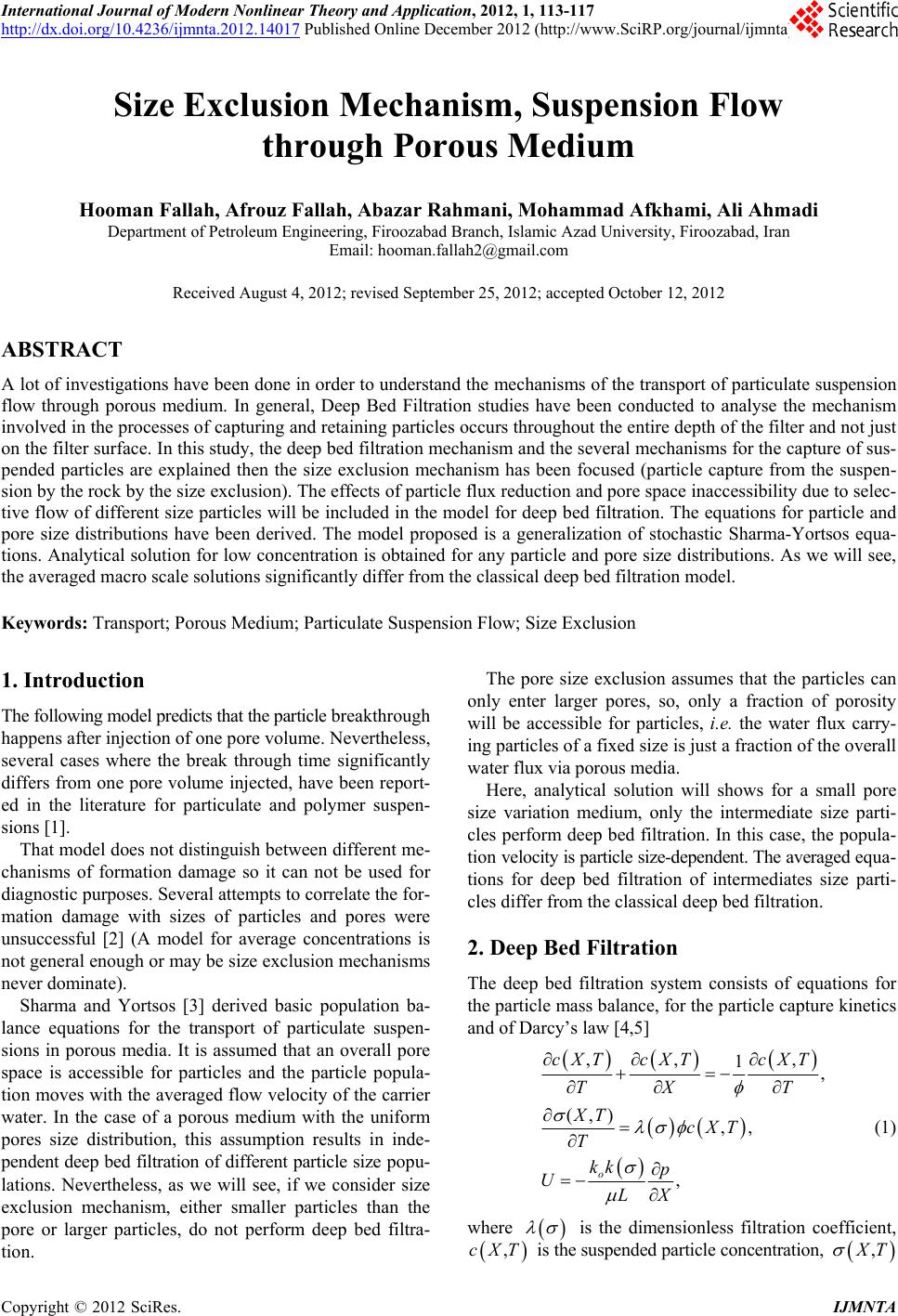
 International Journal of Modern Nonlinear Theory and Application, 2012, 1, 113-117 http://dx.doi.org/10.4236/ijmnta.2012.14017 Published Online December 2012 (http://www.SciRP.org/journal/ijmnta) Size Exclusion Mechanism, Suspension Flow through Porous Medium Hooman Fallah, Afrouz Fallah, Abazar Rahmani, Mohammad Afkhami, Ali Ahmadi Department of Petroleum Engineering, Firoozabad Branch, Islamic Azad University, Firoozabad, Iran Email: hooman.fallah2@gmail.com Received August 4, 2012; revised September 25, 2012; accepted October 12, 2012 ABSTRACT A lot of investigations have been done in order to understand the mechanisms of the transport of particulate suspension flow through porous medium. In general, Deep Bed Filtration studies have been conducted to analyse the mechanism involved in the processes of capturing and retaining particles occurs throughout the entire depth of the filter and not just on the filter surface. In this study, the deep bed filtration mechanism and the several mechanisms for the capture of sus- pended particles are explained then the size exclusion mechanism has been focused (particle capture from the suspen- sion by the rock by the size exclusion). The effects of particle flux reduction and pore space inaccessibility due to selec- tive flow of different size particles will be included in the model for deep bed filtration. The equations for particle and pore size distributions have been derived. The model proposed is a generalization of stochastic Sharma-Yortsos equa- tions. Analytical solution for low concentration is obtained for any particle and pore size distributions. As we will see, the averaged macro scale solutions significantly differ from the classical deep bed filtration model. Keywords: Transport; Porous Medium; Particulate Suspension Flow; Size Exclusion 1. Introduction The following model predicts that the particle breakthrough happens after injection of one pore volume. Nevertheless, several cases where the break through time significantly differs from one pore volume injected, have been report- ed in the literature for particulate and polymer suspen- sions [1]. That model does not distinguish between different me- chanisms of formation damage so it can not be used for diagnostic purposes. Several attempts to correlate the for- mation damage with sizes of particles and pores were unsuccessful [2] (A model for average concentrations is not general enough or may be size exclusion mechanisms never dominate). Sharma and Yortsos [3] derived basic population ba- lance equations for the transport of particulate suspen- sions in porous media. It is assumed that an overall pore space is accessible for particles and the particle popula- tion moves with the averaged flow velocity of the carrier water. In the case of a porous medium with the uniform pores size distribution, this assumption results in inde- pendent deep bed filtration of different particle size popu- lations. Nevertheless, as we will see, if we consider size exclusion mechanism, either smaller particles than the pore or larger particles, do not perform deep bed filtra- tion. The pore size exclusion assumes that the particles can only enter larger pores, so, only a fraction of porosity will be accessible for particles, i.e. the water flux carry- ing particles of a fixed size is just a fraction of the overall water flux via porous media. Here, analytical solution will shows for a small pore size variation medium, only the intermediate size parti- cles perform deep bed filtration. In this case, the popula- tion velocity is particle size-dependent. The averaged equa- tions for deep bed filtration of intermediates size parti- cles differ from the classical deep bed filtration. 2. Deep Bed Filtration The deep bed filtration system consists of equations for the particle mass balance, for the particle capture kinetics and of Darcy’s law [4,5] ,, 1, (,) ,, , o cXT cXTcXT TX T XT cXT T kk p ULX , (1) where is the dimensionless filtration coefficient, ,cXT is the suspended particle concentration, , T C opyright © 2012 SciRes. IJMNTA 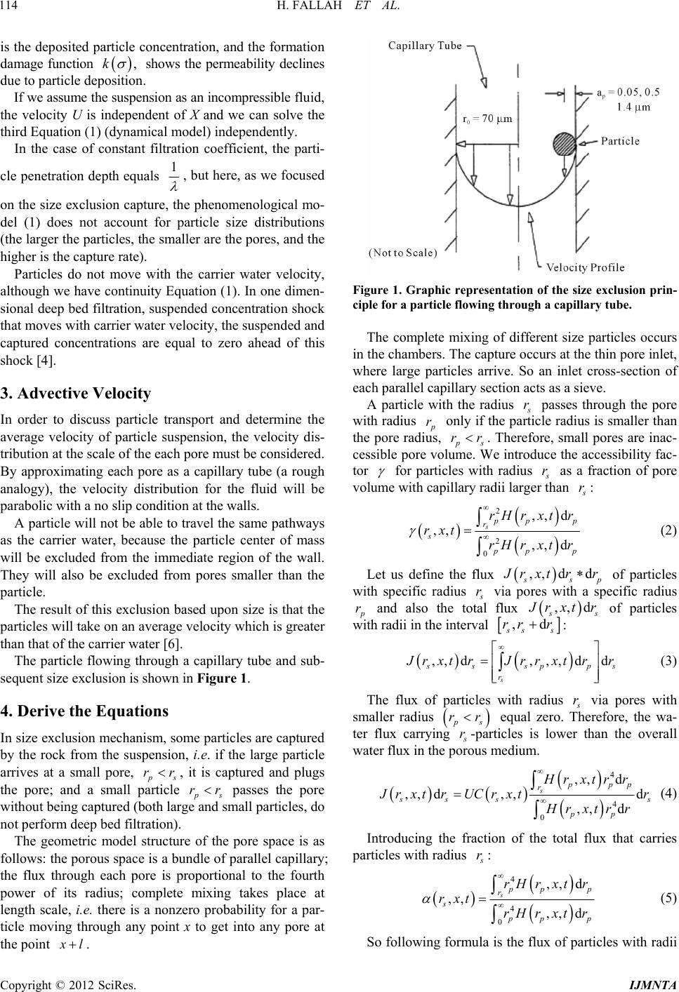 H. FALLAH ET AL. 114 is the deposited particle concentration, and the formation damage function ,k shows the permeability declines due to particle deposition. If we assume the suspension as an incompressible fluid, the velocity U is independent of X and we can solve the third Equation (1) (dynamical model) independently. In the case of constant filtration coefficient, the parti- cle penetration depth equals 1 , but here, as we focused on the size exclusion capture, the phenomenological mo- del (1) does not account for particle size distributions (the larger the particles, the smaller are the pores, and the higher is the capture rate). Particles do not move with the carrier water velocity, although we have continuity Equation (1). In one dimen- sional deep bed filtration, suspended concentration shock that moves with carrier water velocity, the suspended and captured concentrations are equal to zero ahead of this shock [4]. 3. Advective Velocity In order to discuss particle transport and determine the average velocity of particle suspension, the velocity dis- tribution at the scale of the each pore must be considered. By approximating each pore as a capillary tube (a rough analogy), the velocity distribution for the fluid will be parabolic with a no slip condition at the walls. A particle will not be able to travel the same pathways as the carrier water, because the particle center of mass will be excluded from the immediate region of the wall. They will also be excluded from pores smaller than the particle. The result of this exclusion based upon size is that the particles will take on an average velocity which is greater than that of the carrier water [6]. The particle flowing through a capillary tube and sub- sequent size exclusion is shown in Figure 1. 4. Derive the Equations In size exclusion mechanism, some particles are captured by the rock from the suspension, i.e. if the large particle arrives at a small pore, ps , it is captured and plugs the pore; and a small particle ps passes the pore without being captured (both large and small particles, do not perform deep bed filtration). rr rr The geometric model structure of the pore space is as follows: the porous space is a bundle of parallel capillary; the flux through each pore is proportional to the fourth power of its radius; complete mixing takes place at length scale, i.e. there is a nonzero probability for a par- ticle moving through any point x to get into any pore at the point l. Figure 1. Graphic representation of the size exclusion prin- ciple for a particle flowing through a capillary tube. The complete mixing of different size particles occurs in the chambers. The capture occurs at the thin pore inlet, where large particles arrive. So an inlet cross-section of each parallel capillary section acts as a sieve. A particle with the radius r passes through the pore with radius p only if the particle radius is smaller than the pore radius, ps r rr . Therefore, small pores are inac- cessible pore volume. We introduce the accessibility fac- tor for particles with radius r as a fraction of pore volume with capillary radii larger than r: 2 2 0 ,, d ,, ,, d spp r s pp rH rxtr rxt rH rxtr p p (2) Let us define the flux ,, dd sp rxt rr of particles with specific radius r via pores with a specific radius p and also the total flux r ,, d s rxt r of particles with radii in the interval ,d ss rr r: ,, d, ,,dd s sspp r s rxtrJrrxtrr (3) The flux of particles with radius r via pores with smaller radius ps rr equal zero. Therefore, the wa- ter flux carrying r-particles is lower than the overall water flux in the porous medium. 4 4 0 ,, d ,, d,,d ,, d sppp r ss pp Hr xtrr s rxt rUCrxtr Hr xtrr (4) Introducing the fraction of the total flux that carries particles with radius r: 4 4 0 ,, d ,, ,, d spp r s pp rH rxtr rxt rH rxtr p p (5) So following formula is the flux of particles with radii Copyright © 2012 SciRes. IJMNTA 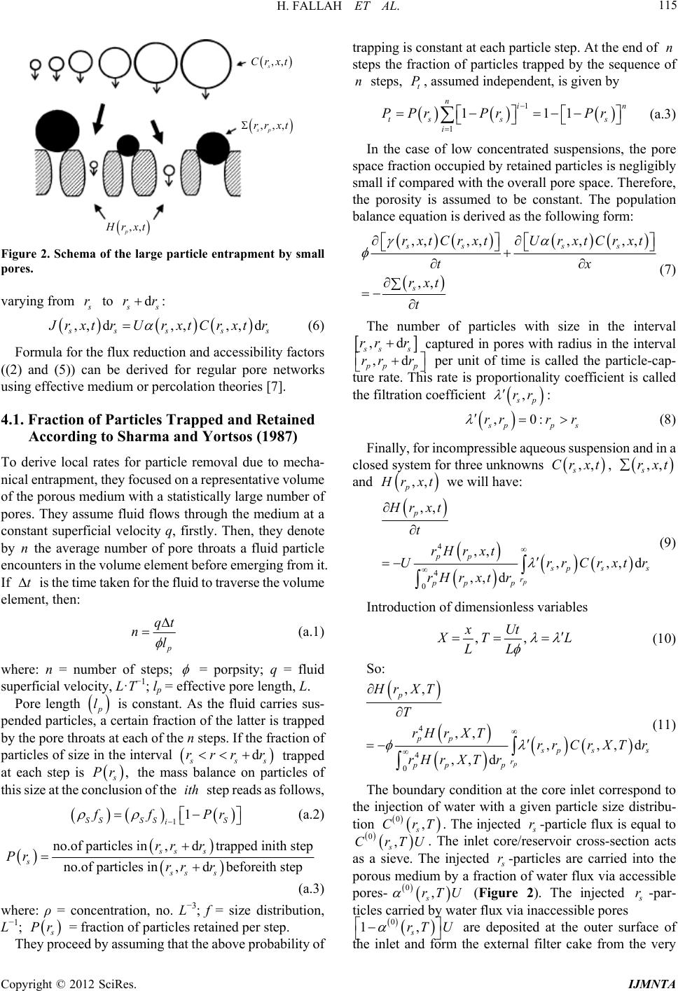 H. FALLAH ET AL. 115 ,, s Crxt ,,, sp rr xt ,, p rxt Figure 2. Schema of the large particle entrapment by small pores. varying from r to d s rr: ,, d,,,, d ss ss rxt rUrxtCrxt r (6) Formula for the flux reduction and accessibility factors ((2) and (5)) can be derived for regular pore networks using effective medium or percolation theories [7]. 4.1. Fraction of Particles Trapped and Retained According to Sharma and Yortsos (1987) To derive local rates for particle removal due to mecha- nical entrapment, they focused on a representative volume of the porous medium with a statistically large number of pores. They assume fluid flows through the medium at a constant superficial velocity q, firstly. Then, they denote by n the average number of pore throats a fluid particle encounters in the volume element before emerging from it. If is the time taken for the fluid to traverse the volume element, then: t p qt nl (a.1) where: n = number of steps; = porpsity; q = fluid superficial velocity, L·T−1; lp = effective pore length, L. Pore length p l is constant. As the fluid carries sus- pended particles, a certain fraction of the latter is trapped by the pore throats at each of the n steps. If the fraction of particles of size in the interval d ss rrr r trapped at each step is s , r the mass balance on particles of this size at the conclusion of the step reads as follows, ith 11 SS SSS i fPr (a.2) no.of particles in,dtrapped inith step no.of particles in,dbeforeith step ss s s ss s rr r Pr rr r (a.3) where: ρ = concentration, no. L−3; f = size distribution, L−1; Pr They proceed = fraction of particles retained per step. by assuming that the above probability of trapping is constant at each particle step. At the end of n steps the fraction of particles trapped by the sequence of n steps, t P, assumed independent, is given by 1 nin 1 111 ts s s i PPr PrPr (a.3) In the case of low concentrated suspensions, the pore space fraction occupied by retained particles is negligibly small if compared with the overall pore space. Therefore, the porosity is assumed to be constant. The population balance equation is derived as the following form: ,, ,,,, ,,rxtCrxtU rxtCrxt ,, ss ss s tx rxt t (7) The number of particles with size in the interval ,d ss r r captured in pores with radius in the interval r ,d pp p rr r per unit of time is called the particle-cap- rate is proportionality coefficient is called the filtration coefficient ture rate. This , p rr : ,0: pp r r s (8) Finally, for incompressible aqueous sus cl r r pension and in a osed system for three unknowns ,, s Cr xt, ,, s rxt and ,, p rxt we will have: 4 4 0 ,, ,, ,,, ,, dp p pp d ps r pp p Hr xt t rH rxt UrrC rH rxtr s rxtr (9) Introduction of dimensionless variables ,, xUt TL LL (10) So: 4 4 0 ,, ,, ,,, ,, d p p pp d ps r pp p s r XT T rH rXTrr CrXTr rH rXTr (11) The boundary condition at the core inlet correspond to th H e injection of water with a given particle size distribu- tion 0, s CrT . The injected r-particle flux is equal to 0 Che inlet core/reservoir cross-section acts he injected , s rTU . T as a sieve. T r-particles are carried into the porous medium by a fraction of water flux via accessible pores- 0, s rTU (Figure 2). The injected r-par- ticles carried by r flux via inaccessible pores 0 1, s rT U wate are deposited at the outer surface of the inlet and form the external filter cake from the very Copyright © 2012 SciRes. IJMNTA  H. FALLAH ET AL. 116 beginning of injection. For particles larger than any pore, there are no accessible pores and the flux reduction factor is zero. So, all these particles are retained at the inlet cross-section, contributing to external filter cake growth. On the other hand, for particles smaller than the smallest pore, they will enter the porous medium without being captured. (deep bed filtration will not perform in both condition).The particles retained at the outer surface of the inlet large particles do not restrict access of newly arriving particles to the core inlet before the transition time [7] Finally, 0 ,,hXTh XXT (12) Equation (12) shows that one particle can po 4.2. Filtration in a Single Pore Size Medium ingle ution (Dirac’s de plug only one re and vice versa. Distribution of suspended particles and pores in a s pore size medium are illustrated bellow. Figure 3(a) shows the pore size distrib lta function) at 0T and the particle size distribu- tion in the injected nsion at 0X. If we consider the propagation of small particles suspe with p rr . For this case, formulae (2) and (5) show that 1 ; i.e. all pores are accessible for small particlesre is no flux reduction. Therefore, sma , and the ll particles are transported with the ve- lo ge particles city of carrier water without being captured (no pores will be plugged by small particles). Now consider the propagation of lar p rr . ws thaIn this case, from Equations (2) and (5) it follot 0 . Therefore, none of the pores is accessible for icles, and there is no large particle flux. So, all large particles are deposited in the inlet cross-section (they never arrive at the core out-let). It was also observed in a laboratory study [8] where size exclusion was the domi- nant capture mechanism. It is important to highli large part ght that, depending on the size, th 5. Highlighted Assumptions uspension is incom- were no deposited particles and plugged pores at th e particles in uniform pore size medium either pass or are trapped. Therefore, the deep bed filtration, where there exists an average penetration length for each size particle, does not happen in the case of particulate flow in a single size porous media. The penetration length is zero for large particles, and is infinite for small particles. It was assumed that the aqueous s pressible so the velocity U in Equation (1) is independent of X and we can solve the third Equation (1) indepen- dently (dynamical model separates from the kinematics model). There e beginning of deep bed filtration. There are no sus- 00 , ss rTcT 00 00pp rh 0p r r (a) 0p r r 00 , pp rThT ,, , ss rXTcXT 00 , ss rT XcT X (b) Figure 3. (a) initial and boary concentration distribu- ended particles ahead of the injected water front. f low co articles retained at the outer su 6. Conclusions ptured during flow through pore sys- are smaller then th analytical solution for flow in a single pore size und tions for pores and suspended particles; (b) particle distri- bution for any X and T; pore distribution at the inlet cross section for T > 0. p The porosity is assumed constant in the case o ncentrated suspensions. We assumed that the p rface of the inlet large particles do not restrict access of newly arriving particles to the core inlet before the tran- sition time [9]. The external cake does not form a solid matrix before the transition time and cannot capture the particles from the injected suspension. Particles are not ca tem, but there is a sequence of particle capturing sieves perpendicular to the flow direction. Absence of particles in the pores that e particles, results in reduction of the particle carrying water flux if compared with the overall water flux. So, only a fraction of the pore space is accessible for parti- cles. The r medium shows that capture free advection of small rticles pa p rr takes place, and large particles p rr netrate into the porous medium (there p bed filtration in a uniform pore size medium). Large particles never arrive at the core outlet. It was do not pe is no dee ob REFERENCES [1] R. Dawson ansible Pore Volume served in a laboratory study [8] where size exclusion was the dominant capture mechanism. d R. B. Lantz, “Inacces Copyright © 2012 SciRes. IJMNTA  H. FALLAH ET AL. Copyright © 2012 SciRes. IJMNTA 117 F. G. van Velzen and K. Leerlooijer, “Im- . C. Yortsos, “Transport of Particu- in Polymer Flooding,” SPE Journal, Vol. 12, No. 5, 1972, pp. 448-452. [2] E. V. Oort, J. pairment by Suspended Solids Invasion: Testing and Pre- diction,” SPE Production & Facilities, Vol. 8, No. 3, 1993, pp. 178-184. [3] M. M. Sharma and Y late Suspensions in Porous Media: Model Formulation,” AIChE Journal, Vol. 33, No. 10, 1987, pp. 1636-1643. doi:10.1002/aic.690331007 [4] J. P. Herzig, D. M. Leclerc and P. Le Goff, “Flow of Sus- Filtration,” American ar, “Particle Transport in Flow through Porous d V. V. Kadet, “Percolation Models in and M. M Sharma, “A Model for Predicting In- ort of pension through Porous Media—Application to Deep Fil- tration,” Journal of Industrial and Engineering Chemis- try, Vol. 62, No. 5, 1970, pp. 8-35. [5] T. Iwasaki, “Some Notes on Sand Water Works Association, Vol. 29, No. 10, 1937, pp. 1591- 1602. [6] R. Edg Media: Advection, Longitudinal Dispersion and Filtra- tion,” Ph.D. Thesis, California Institute of Technology, Pasadena, 1992. [7] V. I. Seljakov an Porous Media,” Kluwer Academic Publishers, Dordrecht, 1996. [8] S. Pang jectivity Decline in Water-Injection Wells,” SPE Forma- tion Evaluation, Vol. 12, No. 3, 1997, pp. 194-201. [9] N. Massei, M. Lacroix and H. Q. Wang, “Transp Particulate Material and Dissolved Tracer in a Highly Permeable Porous Medium,” Journal of Contaminant Hydrology, Vol. 57, No. 1-2, 2002, pp. 21-39. Table of Symbols dynamic Peclet numberSg D L V Pd eD suspended particle concentration in carrier fluid;c 3 particle concenterationCM article retained concentration; L; longitudinal position;andxL detachment rate coefficient; det k flow velocity;U 1 filter coefficient.L article settling velocit s w fluid velocity; S Uy; article velocityU fluid interstitial velocity;V ; P fluid center line vU densities of particle and f s elocity; O radial distance;r luid, respectively; pf gravitational accelerationg ; capillary radius; o r article radiusaHamakar constantergs;H gravitational groupN p dynamicpressurep ; GG 21 spersion coefficientDLparticle longitudinal di LP ; longitudinal distance;x 1 longitudinal dispersioncoefficient; L D free fluid molecular diffusion coefficient of solD LT T particle molecular diffusi P D ; on coefficient in a 21 free fluid;LT 21 ute 21 article veloci Pty ;VL ;LT 1 interstitial velocity; andVL T T media grain diameter; g dL and particle diameterdL fluid Sp Peclet numberSg Vd Pe D
|