 World Journal of Mechanics, 2012, 2, 239-245 doi:10.4236/wjm.2012.25029 Published Online October 2012 (http://www.SciRP.org/journal/wjm) A Computer Program for Dynamic Load Simulation of Spur Gears with Asymmetric and Symmetric Teeth Fatih Karpat1, Stephen Ekwaro-Osire2, Esin Karpat3 1Department of Mechanical Engineering, Uludag University, Bursa, Turkey 2Department of Mechanical Engineering, Texas Tech University, Lubbock, USA 3Department of Electronics Engineering, Uludag University, Bursa, Turkey Email: karpat@uludag.edu.tr, stephen.ekwaro-osire@ttu.edu, esinoz@uludag.edu.tr Received August 2, 2012; revised September 1, 2012; accepted September 12, 2012 ABSTRACT An important concern in gear design is to reduce the dynamic load and noise of gear systems. It has been found that the noise generated from gearing is basically due to gearbox vibration excited by the dynamic load. Since one of the situa- tions that demand high performance is the high rotational speeds, there is a need to understand the dynamic behavior of the gears at such speeds. Such knowledge would shed light on detrimental characteristics like dynamic loads and vibra- tions. An efficient way in performing studies on the dynamic behavior of gears is using computer aided analysis on nu- merical models. In this paper, a developed computer program is introduced to analyze dynamic behavior of spur gears with asymmetric teeth that have a potential use for higher performance in wind turbine gearboxes. This program can be used to compare conventional spur gears with symmetric teeth and spur gears with asymmetric teeth. By using this pro- gram, gear designers can design a gear pair and obtain results, e.g. dynamic Load, transmitted torque, static transmis- sion error, and frequency spectra of static transmission error etc., just by pressing a command button. Keywords: Gears; Computer Program; Asymmetric Teeth 1. Introduction Gear dynamics has been a subject of intense interest to the gearing area during the last few decades dynamic loads and vibration are a major concern for gear drives at high speeds. Simulation of meshing of gear drives per- formed by application of tooth contact analysis and ex- perimental tests of gear drives have confirmed that trans- mission errors (TE) are the prime cause of noise and vi- brations of the gear drives [1]. The definition of trans- mission error is made as “The difference between the actual position of the output gear and the position it would occupy if the gear drive were perfectly conjugate”. This may be expressed as angular displacement or as linear displacement at the pitch point [2]. The causes of transmission error are elastic deflections under load, geometrical errors and geometrical modifications. Transmission errors causing dynamic loads in gears affect not only the gear vibrations and noise but also tooth fatigue, and surface failure. Therefore, the most important objective in gear design is the minimization of dynamic loads and transmission errors. There have been many studies on gear design in lit- erature. The prediction of gear transmission errors and gear dynamic loads, gear noise and vibration for gear drives are always main concerns in gear design. Com- prehensive reviews on the development of a variety of simulation models for both static and dynamic analysis of different types of gears are presented in [3-5]. Tea- ruchi and Hidetaro [5] used the tooth deflection, equiva- lent composite error, and equivalent mass of gear, in the calculation of the dynamic loads on gear teeth. The nu- merical results obtained were shown to be in good agreement with the experimental results. A similar vi- bratory model was presented in [6]. A comparison of the theoretical and the experimental results, obtained for dynamic characteristics of the heavily loaded spur gears, was made. A numerical approach for the equations of motion that contain the excitation terms due to errors and periodic variation of the mesh stiffness was developed and presented. This method was adapted and employed by several researchers [7-14] to calculate the dynamic contact load or the torsional response, depending on dif- ferent gear parameters, i.e. tooth errors, addendum modi- fication, mesh stiffness, lubrication, damping factor, gear contact factor, and friction coefficient. In gear design, the dynamic factor is generally used to quantify the dynamic effects. In this context, the dynamic factor is defined as the ratio of the maximum dynamic load to the maximum static load on the gear tooth. Dynamic loads of gears with low contact ratio (contact ratio is between 1 and 2) are affected by several parameters, namely, time-varying Copyright © 2012 SciRes. WJM 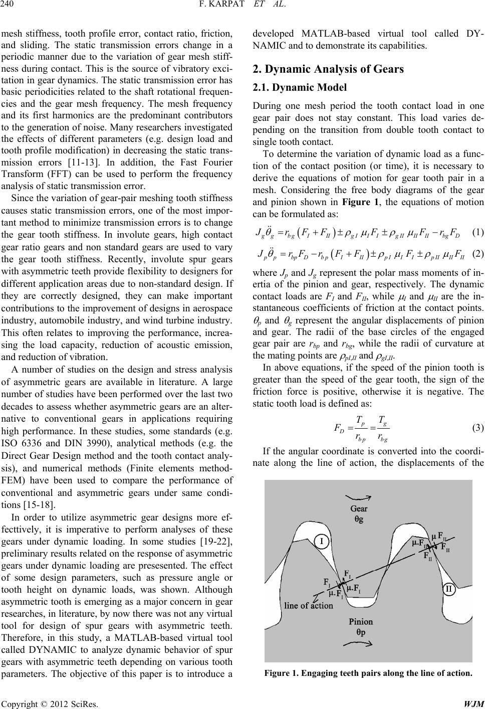 F. KARPAT ET AL. 240 mesh stiffness, tooth profile error, contact ratio, friction, and sliding. The static transmission errors change in a periodic manner due to the variation of gear mesh stiff- ness during contact. This is the source of vibratory exci- tation in gear dynamics. The static transmission error has basic periodicities related to the shaft rotational frequen- cies and the gear mesh frequency. The mesh frequency and its first harmonics are the predominant contributors to the generation of noise. Many researchers investigated the effects of different parameters (e.g. design load and tooth profile modification) in decreasing the static trans- mission errors [11-13]. In addition, the Fast Fourier Transform (FFT) can be used to perform the frequency analysis of static transmission error. Since the variation of gear-pair meshing tooth stiffness causes static transmission errors, one of the most impor- tant method to minimize transmission errors is to change the gear tooth stiffness. In involute gears, high contact gear ratio gears and non standard gears are used to vary the gear tooth stiffness. Recently, involute spur gears with asymmetric teeth provide flexibility to designers for different application areas due to non-standard design. If they are correctly designed, they can make important contributions to the improvement of designs in aerospace industry, automobile industry, and wind turbine industry. This often relates to improving the performance, increa- sing the load capacity, reduction of acoustic emission, and reduction of vibration. A number of studies on the design and stress analysis of asymmetric gears are available in literature. A large number of studies have been performed over the last two decades to assess whether asymmetric gears are an alter- native to conventional gears in applications requiring high performance. In these studies, some standards (e.g. ISO 6336 and DIN 3990), analytical methods (e.g. the Direct Gear Design method and the tooth contact analy- sis), and numerical methods (Finite elements method- FEM) have been used to compare the performance of conventional and asymmetric gears under same condi- tions [15-18]. In order to utilize asymmetric gear designs more ef- fecttively, it is imperative to perform analyses of these gears under dynamic loading. In some studies [19-22], preliminary results related on the response of asymmetric gears under dynamic loading are presesented. The effect of some design parameters, such as pressure angle or tooth height on dynamic loads, was shown. Although asymmetric tooth is emerging as a major concern in gear researches, in literature, by now there was not any virtual tool for design of spur gears with asymmetric teeth. Therefore, in this study, a MATLAB-based virtual tool called DYNAMIC to analyze dynamic behavior of spur gears with asymmetric teeth depending on various tooth parameters. The objective of this paper is to introduce a developed MATLAB-based virtual tool called DY- NAMIC and to demonstrate its capabilities. 2. Dynamic Analysis of Gears 2.1. Dynamic Model During one mesh period the tooth contact load in one gear pair does not stay constant. This load varies de- pending on the transition from double tooth contact to single tooth contact. To determine the variation of dynamic load as a func- tion of the contact position (or time), it is necessary to derive the equations of motion for gear tooth pair in a mesh. Considering the free body diagrams of the gear and pinion shown in Figure 1, the equations of motion can be formulated as: gbgIIIgII IgIIII IIbgD rFFF FrF && (1) pbpDb pIIIp IIIp IIIIII rFr F FFF && (2) where Jp and Jg represent the polar mass moments of in- ertia of the pinion and gear, respectively. The dynamic contact loads are FI and FII, while I and II are the in- stantaneous coefficients of friction at the contact points. p and g represent the angular displacements of pinion and gear. The radii of the base circles of the engaged gear pair are rbp and rbg, while the radii of curvature at the mating points are pI,II and gI,II. In above equations, if the speed of the pinion tooth is greater than the speed of the gear tooth, the sign of the friction force is positive, otherwise it is negative. The static tooth load is defined as: g Dbp bg TT Frr (3) If the angular coordinate is converted into the coordi- nate along the line of action, the displacements of the Figure 1. Engaging teeth pairs along the line of action. Copyright © 2012 SciRes. WJM 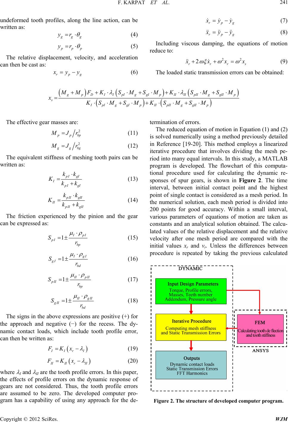 F. KARPAT ET AL. Copyright © 2012 SciRes. WJM 241 undeformed tooth profiles, along the line action, can be written as: rpg yy &&& (7) gg yr (4) rpg yy &&&&&& (8) Including viscous damping, the equations of motion reduce to: pp yr (5) The relative displacement, velocity, and acceleration can then be cast as: 22 2 rrrs xx &&& x (9) rpg yy (6) The loaded static transmission errors can be obtained: pDI IpIggIpIIIIpIIggIIp s IpIggIp IIpIIggIIp MMFKSMSM KSMSM xKSMSMK SMSM The effective gear masses are: 2 pbp Jr (11) 2 gbg Jr (12) The equivalent stiffness of meshing tooth pairs can be written as: IgI I IgI kk Kkk (13) II gII II II gII kk Kkk (14) The friction experienced by the pinion and the gear can be expressed as: 1 pI pI bp Sr (15) 1 gI gI bd Sr (16) 1 IpII pII bp Sr (17) 1 IgII gII bd Sr (18) The signs in the above expressions are positive (+) for the approach and negative (−) for the recess. The dy- namic contact loads, which include tooth profile error, can then be written as: Ir I FKx (19) IIIrII FKx (20) where I and II are the tooth profile errors. In this paper, the effects of profile errors on the dynamic response of gears are not considered. Thus, the tooth profile errors are assumed to be zero. The developed computer pro- gram has a capability of using any approach for the de- termination of errors. The reduced equation of motion in Equation (1) and (2) is solved numerically using a method previously detailed in Reference [19-20]. This method employs a linearized iterative procedure that involves dividing the mesh pe- riod into many equal intervals. In this study, a MATLAB program is developed. The flowchart of this computa- tional procedure used for calculating the dynamic re- sponses of spur gears, is shown in Figure 2. The time interval, between initial contact point and the highest point of single contact is considered as a mesh period. In the numerical solution, each mesh period is divided into 200 points for good accuracy. Within a small interval, various parameters of equations of motion are taken as constants and an analytical solution obtained. The calcu- lated values of the relative displacement and the relative velocity after one mesh period are compared with the initial values xr and vr. Unless the differences between procedure is repeated by taking the previous calculated Figure 2. The structure of developed computer program. 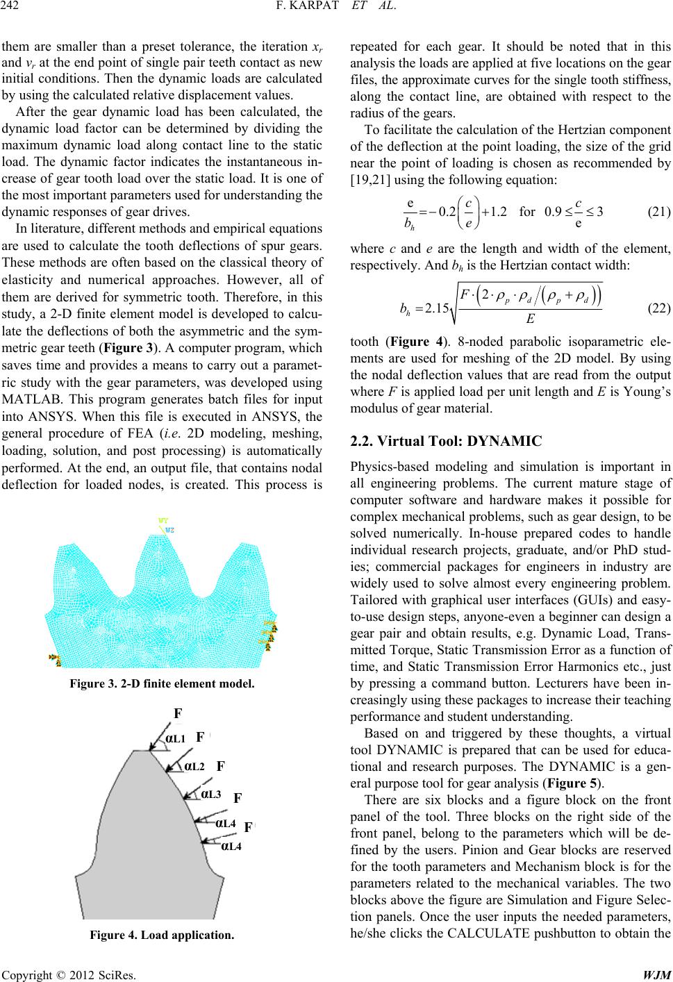 F. KARPAT ET AL. 242 them are smaller than a preset tolerance, the iteration xr and vr at the end point of single pair teeth contact as new initial conditions. Then the dynamic loads are calculated by using the calculated relative displacement values. After the gear dynamic load has been calculated, the dynamic load factor can be determined by dividing the maximum dynamic load along contact line to the static load. The dynamic factor indicates the instantaneous in- crease of gear tooth load over the static load. It is one of the most important parameters used for understanding the dynamic responses of gear drives. In literature, different methods and empirical equations are used to calculate the tooth deflections of spur gears. These methods are often based on the classical theory of elasticity and numerical approaches. However, all of them are derived for symmetric tooth. Therefore, in this study, a 2-D finite element model is developed to calcu- late the deflections of both the asymmetric and the sym- metric gear teeth (Figure 3). A computer program, which saves time and provides a means to carry out a paramet- ric study with the gear parameters, was developed using MATLAB. This program generates batch files for input into ANSYS. When this file is executed in ANSYS, the general procedure of FEA (i.e. 2D modeling, meshing, loading, solution, and post processing) is automatically performed. At the end, an output file, that contains nodal deflection for loaded nodes, is created. This process is Figure 3. 2-D finite element model. α L2 α L1 α L3 α L4 F F F F F α L4 Figure 4. Load application. repeated for each gear. It should be noted that in this analysis the loads are applied at five locations on the gear files, the approximate curves for the single tooth stiffness, along the contact line, are obtained with respect to the radius of the gears. To facilitate the calculation of the Hertzian component of the deflection at the point loading, the size of the grid near the point of loading is chosen as recommended by [19,21] using the following equation: e0.2 1.2 h c be for 0.9 3 e c (21) where c and e are the length and width of the element, respectively. And bh is the Hertzian contact width: 2 2.15 pdp d h F bE (22) tooth (Figure 4). 8-noded parabolic isoparametric ele- ments are used for meshing of the 2D model. By using the nodal deflection values that are read from the output where F is applied load per unit length and E is Young’s modulus of gear material. 2.2. Virtual Tool: DYNAMIC Physics-based modeling and simulation is important in all engineering problems. The current mature stage of computer software and hardware makes it possible for complex mechanical problems, such as gear design, to be solved numerically. In-house prepared codes to handle individual research projects, graduate, and/or PhD stud- ies; commercial packages for engineers in industry are widely used to solve almost every engineering problem. Tailored with graphical user interfaces (GUIs) and easy- to-use design steps, anyone-even a beginner can design a gear pair and obtain results, e.g. Dynamic Load, Trans- mitted Torque, Static Transmission Error as a function of time, and Static Transmission Error Harmonics etc., just by pressing a command button. Lecturers have been in- creasingly using these packages to increase their teaching performance and student understanding. Based on and triggered by these thoughts, a virtual tool DYNAMIC is prepared that can be used for educa- tional and research purposes. The DYNAMIC is a gen- eral purpose tool for gear analysis (Figure 5). There are six blocks and a figure block on the front panel of the tool. Three blocks on the right side of the front panel, belong to the parameters which will be de- fined by the users. Pinion and Gear blocks are reserved for the tooth parameters and Mechanism block is for the parameters related to the mechanical variables. The two blocks above the figure are Simulation and Figure Selec- tion panels. Once the user inputs the needed parameters, he/she clicks the CALCULATE pushbutton to obtain the Copyright © 2012 SciRes. WJM  F. KARPAT ET AL. Copyright © 2012 SciRes. WJM 243 3. Conclusion solution for the specified parameters. In the Figure Se- lection block, from the pop-up menu, user can select which solution to be plotted: Dynamic Load, Transmitted Torque, Static Transmission Error or Static Transmission Error Harmonics. Then the required figure can be plotted with the PLOT button. Once the solutions are calculated, it is not needed to run the program again and again for each figure option. CLEAR is to clean the figure axes before each plot. In this paper, a MATLAB-based virtual tool, DYNAMIC, is introduced to analyze dynamic behavior of spur gears with asymmetric tooth design. The DYNAMIC can be used to compare conventional spur gears with symmetric teeth and spur gears with asymmetric teeth. The results for dynamic load, dynamic factor, transmitted torque, static transmission error and static transmission error harmonics can be obtained for various tooth parameters to show the powerful aspects of asymmetric teeth. Influ- ence of various parameters (e.g. the pressure angle on drive side or coast side, addendum, and teeth number) on the static transmission errors, the amplitudes of harmon- ics of the static transmission errors and the dynamic loads can be investigated. By using this program, gear designers can design a gear pair and obtain results, e.g. dynamic load, transmitted torque, static transmission error, and frequency spectra of static transmission error etc., just by pressing a command button. The variation of dynamic load, static transmission er- rors, static transmission error harmonics and, transmitted torque with respect to time can be seen in Figures 6(a)- (c). The solutions for different variables can be plotted in one figure, for comparison. Figure 6(a) shows a sample result for the variation of the static transmission error during a mesh period. In Figure 6(b), the frequency spectra of the static transmission errors obtained by using the fast Fourier transform (FFT) are depicted. DY- NAMIC program can also provide transmitted torque results respect to time for sample gear pairs. Figure 5. The front panel of the DYNAMIC tool. 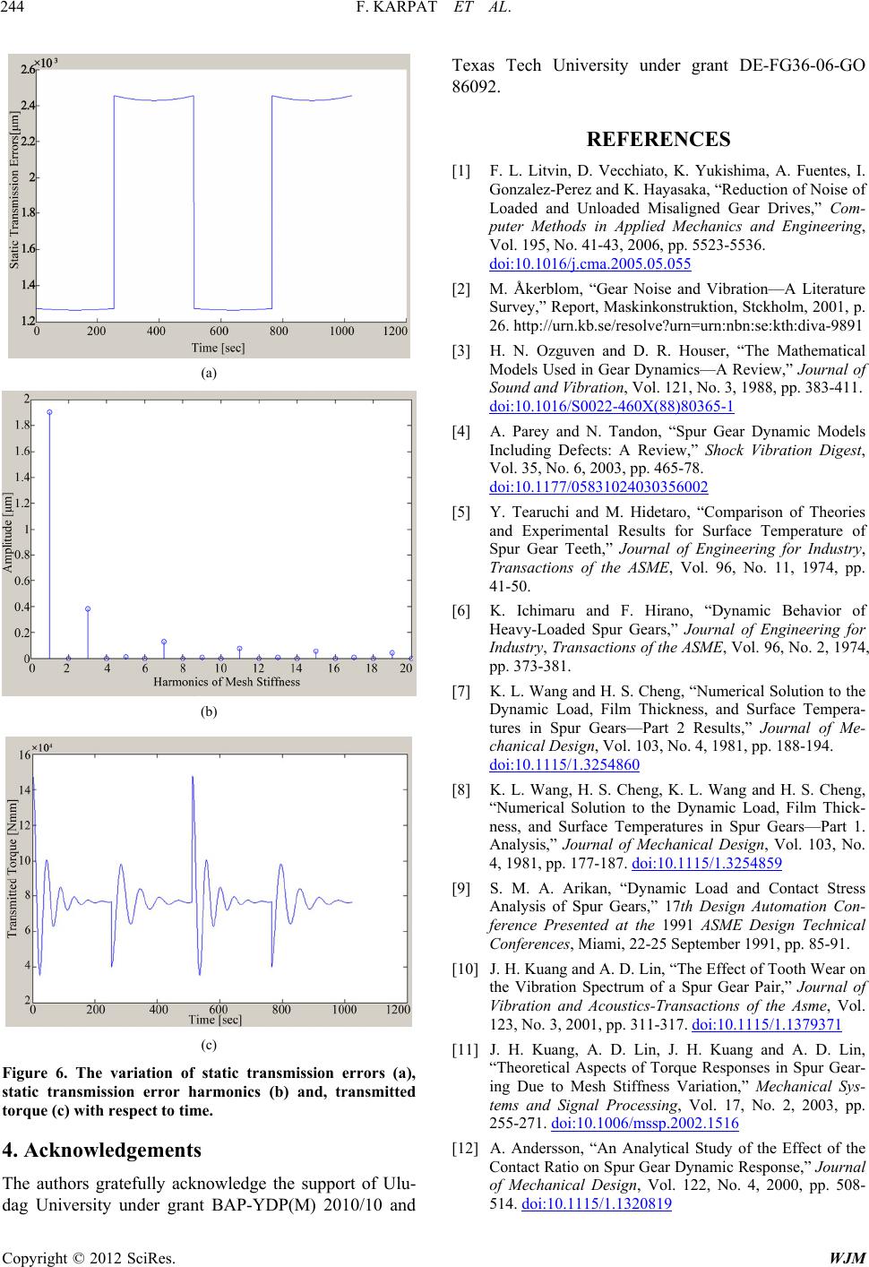 F. KARPAT ET AL. 244 (a) (b) (c) Figure 6. The variation of static transmission errors (a), static transmission error harmonics (b) and, transmitted torque (c) with respect to time. 4. Acknowledgements The authors gratefully acknowledge the support of Ulu- dag University under grant BAP-YDP(M) 2010/10 and Texas Tech University under grant DE-FG36-06-GO 86092. REFERENCES [1] F. L. Litvin, D. Vecchiato, K. Yukishima, A. Fuentes, I. Gonzalez-Perez and K. Hayasaka, “Reduction of Noise of Loaded and Unloaded Misaligned Gear Drives,” Com- puter Methods in Applied Mechanics and Engineering, Vol. 195, No. 41-43, 2006, pp. 5523-5536. doi:10.1016/j.cma.2005.05.055 [2] M. Åkerblom, “Gear Noise and Vibration—A Literature Survey,” Report, Maskinkonstruktion, Stckholm, 2001, p. 26. http://urn.kb.se/resolve?urn=urn:nbn:se:kth:diva-9891 [3] H. N. Ozguven and D. R. Houser, “The Mathematical Models Used in Gear Dynamics—A Review,” Journal of Sound and Vibration, Vol. 121, No. 3, 1988, pp. 383-411. doi:10.1016/S0022-460X(88)80365-1 [4] A. Parey and N. Tandon, “Spur Gear Dynamic Models Including Defects: A Review,” Shock Vibration Digest, Vol. 35, No. 6, 2003, pp. 465-78. doi:10.1177/05831024030356002 [5] Y. Tearuchi and M. Hidetaro, “Comparison of Theories and Experimental Results for Surface Temperature of Spur Gear Teeth,” Journal of Engineering for Industry, Transactions of the ASME, Vol. 96, No. 11, 1974, pp. 41-50. [6] K. Ichimaru and F. Hirano, “Dynamic Behavior of Heavy-Loaded Spur Gears,” Journal of Engineering for Industry, Transactions of the ASME, Vol. 96, No. 2, 1974, pp. 373-381. [7] K. L. Wang and H. S. Cheng, “Numerical Solution to the Dynamic Load, Film Thickness, and Surface Tempera- tures in Spur Gears—Part 2 Results,” Journal of Me- chanical Design, Vol. 103, No. 4, 1981, pp. 188-194. doi:10.1115/1.3254860 [8] K. L. Wang, H. S. Cheng, K. L. Wang and H. S. Cheng, “Numerical Solution to the Dynamic Load, Film Thick- ness, and Surface Temperatures in Spur Gears—Part 1. Analysis,” Journal of Mechanical Design, Vol. 103, No. 4, 1981, pp. 177-187. doi:10.1115/1.3254859 [9] S. M. A. Arikan, “Dynamic Load and Contact Stress Analysis of Spur Gears,” 17th Design Automation Con- ference Presented at the 1991 ASME Design Technical Conferences, Miami, 22-25 September 1991, pp. 85-91. [10] J. H. Kuang and A. D. Lin, “The Effect of Tooth Wear on the Vibration Spectrum of a Spur Gear Pair,” Journal of Vibration and Acoustics-Transactions of the Asme, Vol. 123, No. 3, 2001, pp. 311-317. doi:10.1115/1.1379371 [11] J. H. Kuang, A. D. Lin, J. H. Kuang and A. D. Lin, “Theoretical Aspects of Torque Responses in Spur Gear- ing Due to Mesh Stiffness Variation,” Mechanical Sys- tems and Signal Processing, Vol. 17, No. 2, 2003, pp. 255-271. doi:10.1006/mssp.2002.1516 [12] A. Andersson, “An Analytical Study of the Effect of the Contact Ratio on Spur Gear Dynamic Response,” Journal of Mechanical Design, Vol. 122, No. 4, 2000, pp. 508- 514. doi:10.1115/1.1320819 Copyright © 2012 SciRes. WJM  F. KARPAT ET AL. 245 [13] R . Kasuba and J. W. Evans, “An Extended Model for Determining Dynamic Loads in Spur Gearing,” Journal of Mechanical Design, Vol. 103, No. 2, 1981, pp. 398- 409. doi:10.1115/1.3254920 [14] A. S. Kumar, T. S. Sankar and M. O. M. Osman, “On Dynamic Tooth Load and Stability a Spur-Gear System Using the State-Space Approach,” Journal of Mecha- nisms, Transmissions, and Automation in Design, Vol. 107, No. 1, 1985, pp. 54-60. doi:10.1115/1.3258695 [15] K. Cavdar, F. Karpat and F. C. Babalik, “Computer Aided Analysis of Bending Strength of Involute Spur Gears with Asymmetric Profile,” Journal of Mechanical Design, Vol. 127, No. 3, 2005, pp. 477-484. [16] A. Kapelevich, “Geometry and Design of Involute Spur Gears with Asymmetric Teeth,” Mechanism and Machine Theory, Vol. 35, No. 1, 2000, pp. 117-130. doi:10.1016/S0094-114X(99)00002-6 [17] F. Karpat and S. Ekwaro-Osire, “Influence of Tip Relief Modification on the Wear of Spur Gears with Asymmet- ric Teeth,” Tribology Transactions, Vol. 51, No. 5, 2008, pp. 581-588. doi:10.1080/10402000802011703 [18] F. Karpat, S. Ekwaro-Osire and M. P. H. Khandaker, “Probabilistic Analysis of MEMS Asymmetric Gear Tooth,” Journal of Mechanical Design, Vol. 130, No. 4, 2008, pp. 042306.1-042306.6. [19] F. Karpat and S. Ekwaro-Osire, “Influence of Tip Relief Modification on the Wear of Spur Gears with Asymmet- ric Teeth,” Tribology & Lubrication Technology, Vol. 66, No. 6, 2010, pp. 50-60. [20] F. Karpat, S.Ekwaro-Osire, K.Cavdar and F.C. Babalik, “Dynamic Analysis of Involute Spur Gears with Asym- metric Teeth,” International Journal of Mechanical Sci- ences, Vol. 50, No. 12, 2008, pp. 1598-1610. doi:10.1016/j.ijmecsci.2008.10.004 [21] J. J. Coy and C. H. C. Chao, “Method of Selecting Grid Size to Account for Hertz Deformation in Finite Element Analysis of Spur Gears,” Journal of Mechanical Design, Vol. 104, No. 4, 1982, pp. 759-766. doi:10.1115/1.3256429 [22] R. Muthukumar and M. R. Raghavan, “Estimation of Gear Tooth Deflection by the Finite Element Method,” Mechanism and Machine Theory, Vol. 22, No. 2, 1987, pp. 177-181. doi:10.1016/0094-114X(87)90042-5 Copyright © 2012 SciRes. WJM
|