Paper Menu >>
Journal Menu >>
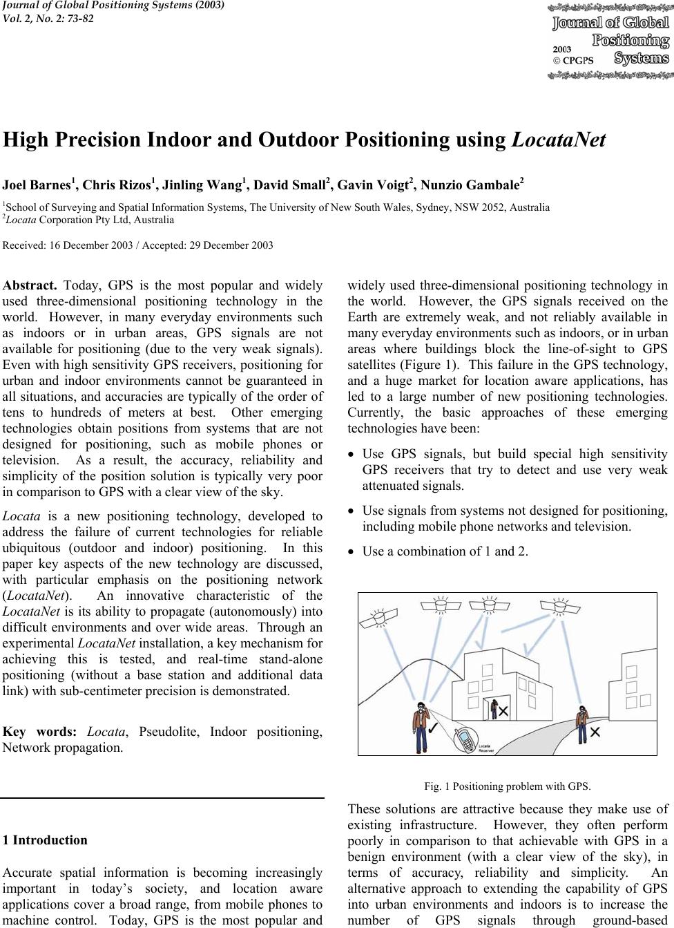 Journal of Global Positioning Systems (2003) Vol. 2, No. 2: 73-82 High Precision Indoor and Outdoor Positioning using LocataNet Joel Barnes1, Chris Rizos1, Jinling Wang1, David Small2, Gavin Voigt2, Nunzio Gambale2 1School of Surveying and Spatial Information Systems, The University of New South Wales, Sydney, NSW 2052, Australia 2Locata Corporation Pty Ltd, Australia Received: 16 December 2003 / Accepted: 29 December 2003 Abstract. Today, GPS is the most popular and widely used three-dimensional positioning technology in the world. However, in many everyday environments such as indoors or in urban areas, GPS signals are not available for positioning (due to the very weak signals). Even with high sensitivity GPS receivers, positioning for urban and indoor environments cannot be guaranteed in all situations, and accuracies are typically of the order of tens to hundreds of meters at best. Other emerging technologies obtain positions from systems that are not designed for positioning, such as mobile phones or television. As a result, the accuracy, reliability and simplicity of the position solution is typically very poor in comparison to GPS with a clear view of the sky. Locata is a new positioning technology, developed to address the failure of current technologies for reliable ubiquitous (outdoor and indoor) positioning. In this paper key aspects of the new technology are discussed, with particular emphasis on the positioning network (LocataNet). An innovative characteristic of the LocataNet is its ability to propagate (autonomously) into difficult environments and over wide areas. Through an experimental LocataNet installation, a key mechanism for achieving this is tested, and real-time stand-alone positioning (without a base station and additional data link) with sub-centimeter precision is demonstrated. Key words: Locata, Pseudolite, Indoor positioning, Network propagation. 1 Introduction Accurate spatial information is becoming increasingly important in today’s society, and location aware applications cover a broad range, from mobile phones to machine control. Today, GPS is the most popular and widely used three-dimensional positioning technology in the world. However, the GPS signals received on the Earth are extremely weak, and not reliably available in many everyday environments such as indoors, or in urban areas where buildings block the line-of-sight to GPS satellites (Figure 1). This failure in the GPS technology, and a huge market for location aware applications, has led to a large number of new positioning technologies. Currently, the basic approaches of these emerging technologies have been: • Use GPS signals, but build special high sensitivity GPS receivers that try to detect and use very weak attenuated signals. • Use signals from systems not designed for positioning, including mobile phone networks and television. • Use a combination of 1 and 2. Fig. 1 Positioning problem with GPS. These solutions are attractive because they make use of existing infrastructure. However, they often perform poorly in comparison to that achievable with GPS in a benign environment (with a clear view of the sky), in terms of accuracy, reliability and simplicity. An alternative approach to extending the capability of GPS into urban environments and indoors is to increase the number of GPS signals through ground-based 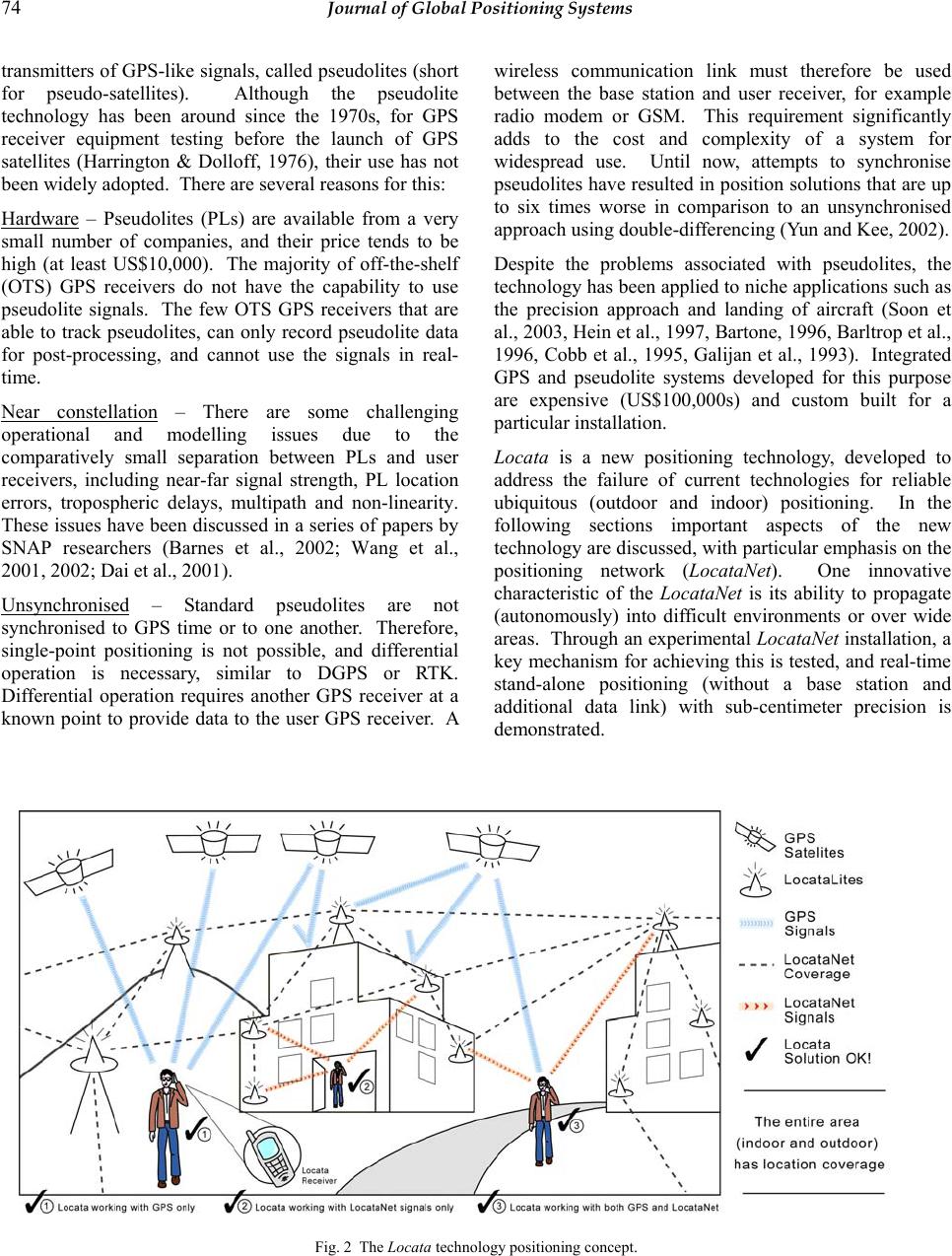 74 Journal of Global Positioning Systems transmitters of GPS-like signals, called pseudolites (short for pseudo-satellites). Although the pseudolite technology has been around since the 1970s, for GPS receiver equipment testing before the launch of GPS satellites (Harrington & Dolloff, 1976), their use has not been widely adopted. There are several reasons for this: Hardware – Pseudolites (PLs) are available from a very small number of companies, and their price tends to be high (at least US$10,000). The majority of off-the-shelf (OTS) GPS receivers do not have the capability to use pseudolite signals. The few OTS GPS receivers that are able to track pseudolites, can only record pseudolite data for post-processing, and cannot use the signals in real- time. Near constellation – There are some challenging operational and modelling issues due to the comparatively small separation between PLs and user receivers, including near-far signal strength, PL location errors, tropospheric delays, multipath and non-linearity. These issues have been discussed in a series of papers by SNAP researchers (Barnes et al., 2002; Wang et al., 2001, 2002; Dai et al., 2001). Unsynchronised – Standard pseudolites are not synchronised to GPS time or to one another. Therefore, single-point positioning is not possible, and differential operation is necessary, similar to DGPS or RTK. Differential operation requires another GPS receiver at a known point to provide data to the user GPS receiver. A wireless communication link must therefore be used between the base station and user receiver, for example radio modem or GSM. This requirement significantly adds to the cost and complexity of a system for widespread use. Until now, attempts to synchronise pseudolites have resulted in position solutions that are up to six times worse in comparison to an unsynchronised approach using double-differencing (Yun and Kee, 2002). Despite the problems associated with pseudolites, the technology has been applied to niche applications such as the precision approach and landing of aircraft (Soon et al., 2003, Hein et al., 1997, Bartone, 1996, Barltrop et al., 1996, Cobb et al., 1995, Galijan et al., 1993). Integrated GPS and pseudolite systems developed for this purpose are expensive (US$100,000s) and custom built for a particular installation. Locata is a new positioning technology, developed to address the failure of current technologies for reliable ubiquitous (outdoor and indoor) positioning. In the following sections important aspects of the new technology are discussed, with particular emphasis on the positioning network (LocataNet). One innovative characteristic of the LocataNet is its ability to propagate (autonomously) into difficult environments or over wide areas. Through an experimental LocataNet installation, a key mechanism for achieving this is tested, and real-time stand-alone positioning (without a base station and additional data link) with sub-centimeter precision is demonstrated. Fig. 2 The Locata technology positioning concept. 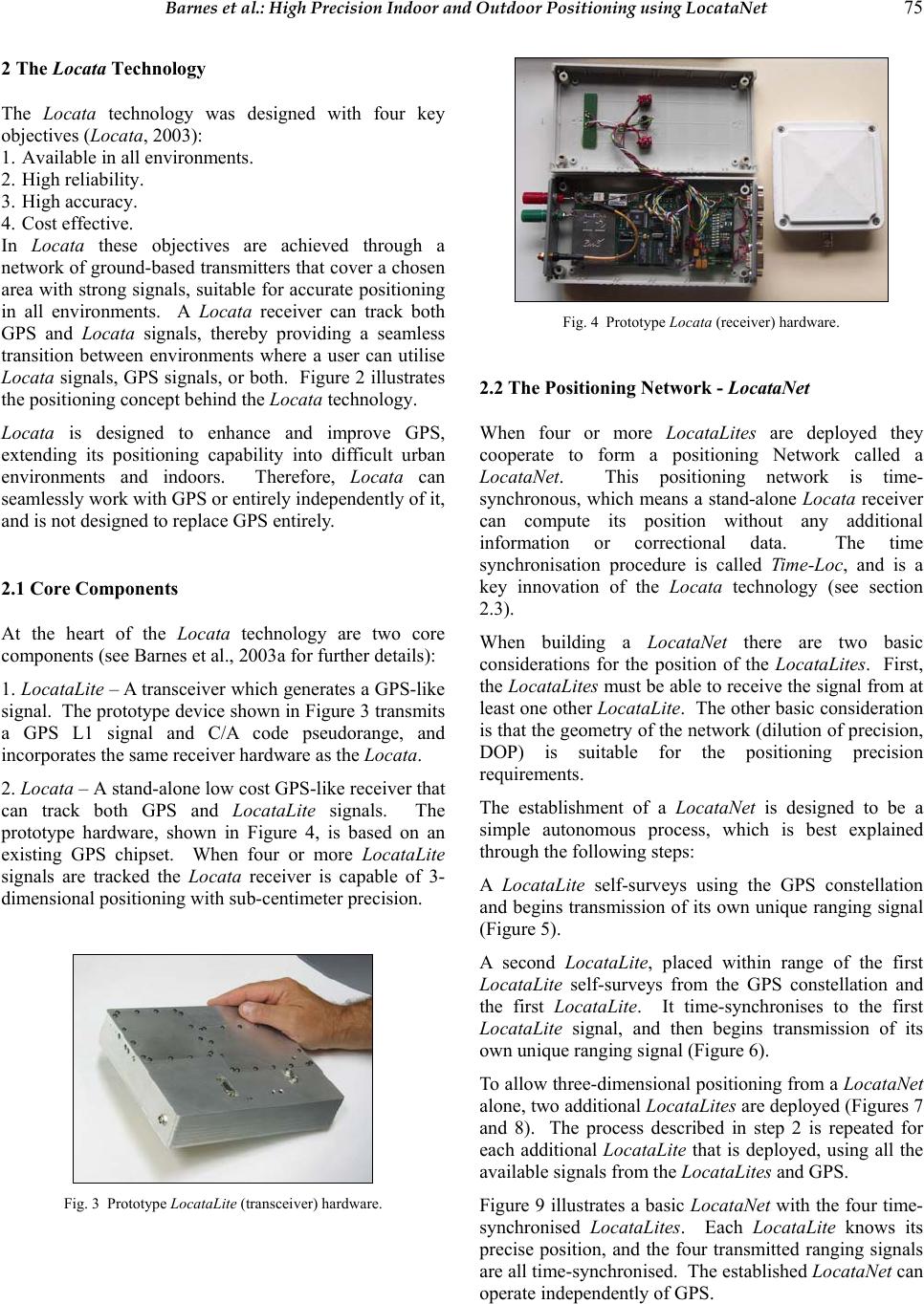 Barnes et al.: High Precision Indoor and Outdoor Positioning using LocataNet 75 2 The Locata Technology The Locata technology was designed with four key objectives (Locata, 2003): 1. Available in all environments. 2. High reliability. 3. High accuracy. 4. Cost effective. In Locata these objectives are achieved through a network of ground-based transmitters that cover a chosen area with strong signals, suitable for accurate positioning in all environments. A Locata receiver can track both GPS and Locata signals, thereby providing a seamless transition between environments where a user can utilise Locata signals, GPS signals, or both. Figure 2 illustrates the positioning concept behind the Locata technology. Locata is designed to enhance and improve GPS, extending its positioning capability into difficult urban environments and indoors. Therefore, Locata can seamlessly work with GPS or entirely independently of it, and is not designed to replace GPS entirely. 2.1 Core Components At the heart of the Locata technology are two core components (see Barnes et al., 2003a for further details): 1. LocataLite – A transceiver which generates a GPS-like signal. The prototype device shown in Figure 3 transmits a GPS L1 signal and C/A code pseudorange, and incorporates the same receiver hardware as the Locata. 2. Locata – A stand-alone low cost GPS-like receiver that can track both GPS and LocataLite signals. The prototype hardware, shown in Figure 4, is based on an existing GPS chipset. When four or more Locata Lite signals are tracked the Locata receiver is capable of 3- dimensional positioning with sub-centimeter precision. Fig. 3 Prototype LocataLite (transceiver) hardware. Fig. 4 Prototype Locata (receiver) hardware. 2.2 The Positioning Network - LocataNet When four or more LocataLites are deployed they cooperate to form a positioning Network called a LocataNet. This positioning network is time- synchronous, which means a stand-alone Locata receiver can compute its position without any additional information or correctional data. The time synchronisation procedure is called Time-Loc, and is a key innovation of the Locata technology (see section 2.3). When building a Locata Net there are two basic considerations for the position of the LocataLites. First, the LocataLites must be able to receive the signal from at least one other LocataLite. The other basic consideration is that the geometry of the network (dilution of precision, DOP) is suitable for the positioning precision requirements. The establishment of a LocataNet is designed to be a simple autonomous process, which is best explained through the following steps: A LocataLite self-surveys using the GPS constellation and begins transmission of its own unique ranging signal (Figure 5). A second LocataLite, placed within range of the first LocataLite self-surveys from the GPS constellation and the first LocataLite. It time-synchronises to the first LocataLite signal, and then begins transmission of its own unique ranging signal (Figure 6). To allow three-dimensional positioning from a LocataNet alone, two additional LocataLites are deployed (Figures 7 and 8). The process described in step 2 is repeated for each additional LocataLite that is deployed, using all the available signals from the LocataLites and GPS. Figure 9 illustrates a basic LocataNet with the four time- synchronised LocataLites. Each LocataLite knows its precise position, and the four transmitted ranging signals are all time-synchronised. The established LocataNet can operate independently of GPS.  76 Journal of Global Positioning Systems Once the LocataNet is established, additional LocataLites can be added, even indoors (Figure 10). A fifth LocataLite placed inside a building can self-survey using only the LocataNet and then begin transmission of its own unique ranging signal. Figure 11 shows an example of a Locata receiver outside using both GPS and LocataLite signals for positioning. Figure 12 shows a Locata receiver inside a building using only Locata Lite signals for positioning, since GPS signals are blocked. Fig. 5 Establishing a LocataNet, step 1. Fig. 6 Establishing a LocataNet, step 2. Fig. 7 Establishing a LocataNet, step 3. Fig. 8 Establishing a LocataNet, step 4. Fig. 9 Establishing a LocataNet, step 5. Fig. 10 Propagating the LocataNet indoors. Fig. 11 Positioning outside using LocataNet and GPS. Fig. 12 . Positioning indoors using LocataNet alone. The Locata Net concept is powerful and has some important characteristics including: Autonomous installation – LocataLites can autonomously survey and negotiate themselves into a positioning network. The self-survey can be from GPS or from an existing LocataNet. This capability makes LocataNet easily expandable to increase signal coverage where  Barnes et al.: High Precision Indoor and Outdoor Positioning using LocataNet 77 necessary, with LocataLites autonomously joining or departing. Ad hoc capability – As well as permanent installation of LocataNets, the autonomous installation and built in networking capability allows for ad hoc networks to be created when required. This is very useful for emergency response type applications or civil engineering projects. Signal penetration – In comparison to GPS signals, LocataLite signals are orders of magnitude stronger. Because of this, signals from a LocataNet can provide significant building penetration. In situations where “deeper” coverage is required, additional LocataLites can be added to the LocataNet inside the building. Seamless positioning with GPS – LocataNet uses the same WGS-84 coordinate system as GPS, allowing a Locata receiver to seamlessly transition from outdoors to indoors, maintaining consistent coordinates. Expansion and coupling – In addition to autonomously adding LocataLites to expand a network, the unique Locata technology provides the capability for LocataNets to join together to form a single continuous network from two or more individual LocataNets . Scalability - LocataNets can be large or small, ranging in size from a room to a large city. Networks could have as few as four LocataLites to thousands of devices. Time-synchronised – LocataNet positioning signals are time-synchronised, which allows single-point positioning in the same manner as GPS. However, unlike GPS the level of synchronisation between LocataLites allows single-point positioning with sub-centimeter precision. The time synchronisation is achieved through an autonomous process known as Time-Loc. 2.3 Time-Loc The time synchronisation accuracy requirements for LocataLites is very high if sub-centimeter positioning precision is desired for a Locata receiver, since a one nanosecond error in time equates to an error of approximately thirty centimeters (due to the speed of light). LocataLites achieve high levels of synchronisation without atomic clocks, external cables, or a master reference receiver. Time-Loc provides an autonomously synchronised network. The Time-Loc procedure is best described in the following steps for two LocataLites A and B (Figure 13): 1. LocataLite A transmits a unique signal (code and carrier). 2. The receiver section of LocataLite B acquires, tracks and measures the signal generated by LocataLite A. Step 1. LocataLite A transmits a unique signal. Step 2. LocataLite B receives signal from A. Step 3. LocataLite B transmits a unique signal. Step 4. LocataLite B computes difference between transmitted and received signals. Step 5. LocataLite B makes difference (in step 4) zero. Step 6. LocataLite B corects for A & B seperation. Fig. 13 Time-Loc procedure.  78 Journal of Global Positioning Systems 3. LocataLite B generates its own unique signal (code and carrier). 4. LocataLite B calculates the difference between the received signal and its own locally generated signal. Ignoring propagation errors, the differences between the two signals are due to the difference in the clocks between the two devices, and the geometric separation between them. 5. LocataLite B adjusts its local oscillator using Direct Digital Synthesis (DDS) technology to bring the differences between its signal and LocataLite A to zero. The signal differences are continually monitored so that they remain zero. In other words, the local oscillator of B follows precisely that of A. 6. The final stage is to correct for the geometrical offset between LocataLite A and B, using the known coordinates of the LocataLites, and after this Time-Loc is achieved. In theory, there is no limit to the number of LocataLites that can be synchronised together using the Time-Loc procedure described previously. Importantly, the Time- Loc procedure allows a LocataNet to propagate into difficult environments or over wide areas. For example, if a third LocataLite C can only receive the signals from B (and not A) then it can use these signals for time- synchronisation instead. Moreover, the only requirement for establishing a Loca taNet using Time-Loc is that LocataLites must receive signals from one other LocataLite. This does not have to be the same ‘central’ or ‘master’ LocataLite, since this is not possible in difficult environments or when propagating the LocataNet over wide areas. The proof-of-concept of LocataNet propagation, and its influence on signal quality, is investigated in section 3. 2.4 Locata Receiver Positioning Accuracy The positioning accuracy of a Locata receiver using only LocataLite signals has been assessed through two experimental LocataNet installations, comprised of five LocataLites. One of the installations is designed for positioning ouside while the other is for indoors. At the outdoor test network (approximately 200x60 meters) with direct line-of-sight signals between the LocataLites and the Locata receiver, static and kinematic point positioning with sub-centimeter and centimeter level precision can be achieved respectively (Barnes et al., 2003a). For the indoor test network (approximately 65x35 meters), the LocataLites are located outside a two- story office building, and the signals penetrate the building (brick walls and a metal roof). Using this LocataNet, indoor static and kinematic real-time positioning can be achieved with sub-centimeter and sub- meter precision respectively (Barnes et al., 2003b). For indoor kinematic positioning with line-of-sight signals, centimeter level positioning is possible. A Locata receiver using a LocataNet has several major advantages in comparison to other currently available positioning technologies (including GPS) which include: Reduced latency – In a differential-based navigation system, the highest positioning accuracies are achieved when a user waits for time-matched base station data (with no interpolation). There is therefore latency associated with base station data transmitted on the communication link. The Locata receiver does not have to wait for any additional data in order to compute a position and therefore has less latency. Theoretically greater precision – In differential GPS the double-differenced observable is formed from four carrier-phase measurements. Assuming all measurements have equal precision and are uncorrelated, the precision of the double-differenced measurement is two times worse than a single carrier-phase measurement (the basic measurement used by the Locata receiver). Time solution – In differential GPS the double- differencing procedure eliminates the clock biases and hence time information is lost. For certain applications precise time is important, and the LocataNet approach allows time to be estimated along with position (as is the case of standard GPS single-point positioning). No data-links – Centimeter level positioning precision can only be achieved with GPS in a differential operating mode. A base station is used along with a wireless link (radio modem or GSM) to communicate data to the user receiver. The base station concept is meaningless in the LocataNet approach, and no radio modem is required at the Locata. Additionally there are no radio modems or hard-wires connecting any of the LocataLite devices. 3. LocataNet Propagation and Signal Quality As discussed in section 2.3 the Time-Loc methodology allows a LocataNet to autonomously propagate into difficult environments and over wide areas, such as an entire city. To demonstrate the proof-of-concept of LocataNet propagation, and its influence on signal quality, an investigation was conducted at an experimental outdoor LocataNet (Figure 14), near Canberra in October 2003. The approach for this investigation was to establish the LocataNet using the Time-Loc procedure in two different ways: 1. Master Time-Loc: The LocataNet was established through all Locata Lites time synchronising to a central ‘master’ LocataLite (32), as illustrated in Figure 15. 2. Cascaded Time-Loc: To simulate the propagation of a LocataNet, time synchronisation was established in four  Barnes et al.: High Precision Indoor and Outdoor Positioning using LocataNet 79 steps: 14 to 32, 29 to 14, 12 to 29, and 21 to 12, as illustrated in Figure 16. In both Time-Loc configurations pairs of LocataLites were time-synchronised in less than ten minutes. It is important to note that the Locata receiver uses the five LocataLite signals from the two LocataNet configurations in exactly the same manner for positioning, as illustrated in Figure 15. Fig. 14 Outdoor experimental LocataNet comprised of five LocataLites. Fig. 15 Master Time-Loc procedure using ‘master’ LocataLite 32. For each LocataNet configuration, the Locata receiver antenna was mounted on a static pole (with known coordinates), at the centre of the LocataNet. The geometric configuration of the LocataLites is such that the dilution of precision (DOP) values at the Locata receiver antenna, in East North and Up are 0.97, 0.70 and 4.25 respectively. The poor DOP in the Up component is due to the fact that the greatest elevation angle from the Locata receiver pole to any LocataLite is 24.5 degrees (32). Before a Locata receiver (in the prototype system) can compute its position using the LocataNet signals, it must first determine carrier-phase biases using the known coordinates of the initial receiver position and the LocataNet (see Barnes et al., 2003a). For each LocataNet configuration these were determined, and then for approximately twenty-three minutes the Locata receiver independently computed real-time position and time solutions once a second. The real-time positions together with the raw measurement data were logged using a laptop computer via a serial interface. Fig. 16 Cascaded Time-Loc procedure, simulating network propagation. Fig. 17 Locata receiver positioning using LocataNet signals from either Master or Cascaded Time-Loc. 3.1 LocataLite Signal Precision A good way to assess the quality of the signals from the LocataLites and how well the LocataNet is time- synchronised is to compute single-difference measurements between the LocataLites. This eliminates the Locata receiver clock error, and shows any time synchronisation errors, and also multipath error. Using the logged measurement data for both Time-Loc procedures, single-difference measurements were computed between LocataLite 32 and all the other LocataLites. The ambiguities of the single-differences were resolved using the known coordinates of the LocataLites and the Locata receiver pole. Figures 18 and 19 show the four single-differences between 32 and the other LocataLites for the Master and Cascaded Time-Loc LocataNets respectively. Most importantly, visually all the single-difference time series on average fit a horizontal line, and do not have any long- 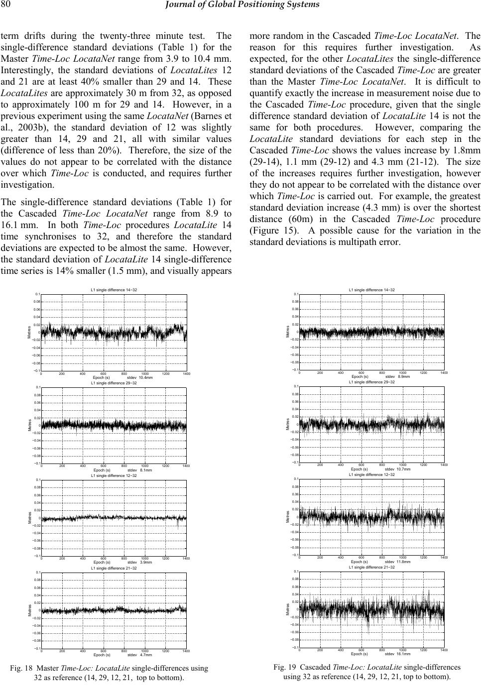 80 Journal of Global Positioning Systems term drifts during the twenty-three minute test. The single-difference standard deviations (Table 1) for the Master Time-Loc LocataNet range from 3.9 to 10.4 mm. Interestingly, the standard deviations of LocataLites 12 and 21 are at least 40% smaller than 29 and 14. These LocataLites are approximately 30 m from 32, as opposed to approximately 100 m for 29 and 14. However, in a previous experiment using the same LocataNet (Barnes et al., 2003b), the standard deviation of 12 was slightly greater than 14, 29 and 21, all with similar values (difference of less than 20%). Therefore, the size of the values do not appear to be correlated with the distance over which Time-Loc is conducted, and requires further investigation. The single-difference standard deviations (Table 1) for the Cascaded Time-Loc LocataNet range from 8.9 to 16.1 mm. In both Time-Loc procedures LocataLite 14 time synchronises to 32, and therefore the standard deviations are expected to be almost the same. However, the standard deviation of LocataLite 14 single-difference time series is 14% smaller (1.5 mm), and visually appears more random in the Cascaded Time-Loc LocataNet. The reason for this requires further investigation. As expected, for the other LocataLites the single-difference standard deviations of the Cascaded Time-Loc are greater than the Master Time-Loc LocataNet. It is difficult to quantify exactly the increase in measurement noise due to the Cascaded Time-Loc procedure, given that the single difference standard deviation of LocataLite 14 is not the same for both procedures. However, comparing the LocataLite standard deviations for each step in the Cascaded Time-Loc shows the values increase by 1.8mm (29-14), 1.1 mm (29-12) and 4.3 mm (21-12). The size of the increases requires further investigation, however they do not appear to be correlated with the distance over which Time-Loc is carried out. For example, the greatest standard deviation increase (4.3 mm) is over the shortest distance (60m) in the Cascaded Time-Loc procedure (Figure 15). A possible cause for the variation in the standard deviations is multipath error. 0200 400 600 80010001200140 0 −0.1 −0.08 −0.06 −0.04 −0.02 0 0.02 0.04 0.06 0.08 0.1 L1 single difference 14−32 Epoch (s) stdev 10.4mm Metres 0200400 60080010001200140 0 −0.1 −0.08 −0.06 −0.04 −0.02 0 0.02 0.04 0.06 0.08 0.1 L1 single difference 29−32 Epoch (s) stdev 8.1mm Metres 0200400 60080010001200140 0 −0.1 −0.08 −0.06 −0.04 −0.02 0 0.02 0.04 0.06 0.08 0.1 L1 single difference 12−32 Epoch (s) stdev 3.9mm Metres 0200400 600800100012001400 −0.1 −0.08 −0.06 −0.04 −0.02 0 0.02 0.04 0.06 0.08 0.1 L1 single difference 21−32 Epoch (s) stdev 4.7mm Metres Fig. 18 Master Time-Loc: LocataLite single-differences using 32 as reference (14, 29, 12, 21, top to bottom). 0200400 60080010001200140 0 −0.1 −0.08 −0.06 −0.04 −0.02 0 0.02 0.04 0.06 0.08 0.1 L1 single difference 14−32 Epoch (s) stdev 8.9mm Metres 0200400 60080010001200140 0 −0.1 −0.08 −0.06 −0.04 −0.02 0 0.02 0.04 0.06 0.08 0.1 L1 single difference 29−32 Epoch (s) stdev 10.7mm Metres 0200400 60080010001200140 0 −0.1 −0.08 −0.06 −0.04 −0.02 0 0.02 0.04 0.06 0.08 0.1 L1 single difference 12−32 Epoch (s) stdev 11.8mm Metres 0200400 600800100012001400 −0.1 −0.08 −0.06 −0.04 −0.02 0 0.02 0.04 0.06 0.08 0.1 L1 single difference 21−32 Epoch (s) stdev 16.1mm Metres Fig. 19 Cascaded Time-Loc: LocataLite single-differences using 32 as reference (14, 29, 12, 21, top to bottom).  Barnes et al.: High Precision Indoor and Outdoor Positioning using LocataNet 81 Single difference stdev (mm) LocataLite Master Time-Loc Cascaded Time-Loc East (14) 10.4 8.9 West (29) 8.1 10.7 North (12) 3.9 11.8 South (21) 4.7 16.1 Tab. 1 LocataLite standard deviations. 3.2 Locata positioning accuracy To assess the accuracy of the real-time positioning results, the known (sub-centimeter) coordinate of the Locata receiver pole was used to compute the positioning error for each epoch in the two different Time-Loc LocataNets. Because of the poor DOP in the Up component, the following discussion will concentrate on horizontal components only. Figures 20 and 21 show the East and North errors for Master and Cascaded Time-Loc LocataNets respectively. For all the time series the mean error is 2mm or less, with standard deviations all less than 8 mm. Clearly sub-centimeter positioning precision has been achieved for both LocataNets. The standard deviations of East and North positioning results in the Cascaded Time-Loc LocataNet are approximately 30% greater than the Master Time-Loc LocataNet. This increase is expected since the LocataLite single- difference measurement time series have greater standard deviations (see section 3.1). However, importantly there are no biases or long term trends introduced as a result of the Cascaded Time-Loc procedure. As expected, the North position standard deviation for both LocataNets is smaller than the East, because the network geometry is slightly better in the North (smaller DOP value, see section 3). 4 Concluding Remarks In this paper important aspects of the Locata technology have been described, with particular focus on the positioning network (LocataNet). Through an outdoor experimental LocataNet installation, proof-of-concept for a propagating positioning network has been demonstrated. In two different LocataNet configurations, one propagating (Cascaded Time-Loc) and the other non- propagating (Master Time-Loc), stand-alone positioning with sub-centimeter level precision was achieved. This level of precision is very pleasing for a prototype system, and is as good as (if not better than) GPS RTK using a base station, radio modem and double differencing. Moreover, the propagating mechanism of LocataNet is a significant innovation, because it allows the positioning network to extend into difficult environments and expand over wide areas. The Locata technology has the potential to deliver high-precision, ubiquitous (outside and inside) positioning for an enormous range of location aware applications, and research and development continues to realise this potential. References Barltrop K.J., J.F. Stafford and B.D. Ellrod (1996) Local DGPS with pseudolite augmentation and implementation considerations for LAAS, Proceedings of 9th Int. Tech. Meeting of the Satellite Division of the U.S. Inst. of Navigation GPS ION-96, Kansas City, Missouri, 17-20 Sept., 449-459. Barnes J., C. Rizos, J. Wang, D. Small, G. Voigt and N. Gambale (2003a) Locata: A new positioning technology 0200400 60080010001200140 0 −0.05 −0.04 −0.03 −0.02 −0.01 0 0.01 0.02 0.03 0.04 0.05 East Epoch (s) stdev 5.4 mm mean 1.4 mm rms 5.6 mm Error (metres) 0200400 60080010001200140 0 −0.05 −0.04 −0.03 −0.02 −0.01 0 0.01 0.02 0.03 0.04 0.05 North Epoch (s) stdev 4.1 mm mean −2.0 mm rms 4.6 mm Error (metres) Fig. 20 Master Time-Loc: Locata receiver East and North static positioning error. 0200 400 600 80010001200140 0 −0.05 −0.04 −0.03 −0.02 −0.01 0 0.01 0.02 0.03 0.04 0.05 East Epoch (s) stdev 7.7 mm mean 1.0 mm rms 7.8 mm Error (metres) 0200400 60080010001200140 0 −0.05 −0.04 −0.03 −0.02 −0.01 0 0.01 0.02 0.03 0.04 0.05 North Epoch (s) stdev 5.9 mm mean −1.5 mm rms 6.1 mm Error (metres) Fig. 21 Cascaded Time-Loc: Locata East and North static positioning error.  82 Journal of Global Positioning Systems for high precision indoor and outdoor positioning, 16th Int. Tech. Meeting of the Satellite Division of the U.S. Inst. of Navigation, Portland, Oregon, 9-12 September. Barnes J., C. Rizos, J. Wang, D. Small, G. Voigt and N. Gambale (2003b) Locata: the positioning technology of the future? 6th International Symposium on Satellite Navigation Technology Including Mobile Positioning & Location Services, Melbourne, Australia, 22-25 July, CD- ROM proc. paper 49. Barnes J., C. Rizos, J. Wang, T. Nunan and C. Reid (2002) The development of a GPS/Pseudolite positioning system for vehicle tracking at BHP Steel, Port Kembla Steelworks, 15th International Technical Meeting of the Satellite Division of The Institute of Navigation ION GPS 2002, Portland, Oregon, 24-27 September, 1779-1789. Bartone C.G. (1996) Advanced pseudolite for dual-use precision approach applications, Proceedings of 9th Int. Tech. Meeting of the Satellite Division of the U.S. Inst. of Navigation, Kansas City, Missouri, 17-20 Sept., 95-105. Cobb H.S., D. Lawrence, B. Pervan, C. Cohen, J.D. Powell and B.W. Parkinson (1995) Precision landing tests with improved integrity beacon pseudolites, Proceedings of 8th Int. Tech. Meeting of the Satellite Division of the U.S. Inst. of Navigation, Palm Springs, California, 12-15 Sept., 827-833. Dai L., C. Rizos and J. Wang (2001) The role of pseudosatellite signals in precise GPS-based positioning, Journal of Geospatial Engineering, 3(1), 33-44. Galijan R.C. and G.V. Lucha (1993) A suggested approach for augmenting GNSS category III approaches and landings: the GPS/Glonass and Glonass pseudolite system, Proceedings of 6th Int. Tech. Meeting of the Satellite Division of the U.S. Inst. of Navigation, Salt Lake City, Utah, 22-24 Sept., 157-160. Harrington R.L. and J.T. Dolloff (1976) The inverted range: GPS user test facility, Proceedings of IEEE PLANS’76, San Diego, California, 1-3 Nov., 204-211. Hein G.W., B.W. Werner, B. Ott, B.D. Elrod, K.J. Barltrop and J.F. Stafford (1997) Practical investigation on DGPS for aircraft precision approaches augmented by pseudolite carrier-phase tracking, Proceedings of 10th Int. Tech. Meeting of the Satellite Division of the U.S. Inst. of Navigation, Kansas City, Missouri, 16-19 Sept.,1851- 1860. Locata Corporation (2003) Locata Technology Primer, Version 1.1. Soon B.H.K, E.K. Poh, J. Barnes, J. Zhang, H.K. Lee, H.K. Lee and C. Rizos (2003) Flight test results of precision approach and landing augmented by airport pseudolites, 16th Int. Tech. Meeting of the Satellite Division of the U.S. Inst. of Navigation, Portland, Oregon, 9-12 September. Yun D. and C. Kee (2002) Centimeter accuracy stand-alone indoor navigation system by synchronized pseudolite constellation, 15th International Technical Meeting of the Satellite Division of The Institute of Navigation ION GPS 2002, Portland, Oregon, 24-27 September, 213-225. Wang J. (2002) Applications of pseudolites in geodetic positioning: Progress and problems, Journal of Global Positioning Systems, 1(1), 48-56. Wang J., T. Tsujii, C. Rizos, L. Dai and M. Moore (2001) GPS and pseudo-satellites integration for precise positioning, Geomatics Research Australasia, 74, 103-117. |