Smart Grid and Renewable Energy, 2012, 3, 207-213
http://dx.doi.org/10.4236/sgre.2012.33029 Published Online August 2012 (http://www.SciRP.org/journal/sgre) 207
Conception of the Solar Regulator for Renewable Energy
Seddik Bri, Mohammed Elalami, Abdelrhani Nakheli
Electrical Engineering Department, High School of Technology, ESTM, Moulay Ismail University, Meknes, Morocco.
Email: briseddik@gmail.com
Received May 14th, 2012; revised June 29th, 2012; accepted July 5th, 2012
ABSTRACT
In this work, we are interested in conducting a technological research on the use of the renewable energy, particularly
the “photovoltaic” to achieve a complete system for the controlled production of energy. In fact, we talked about the
different types of renewable energy and their importance to the economic sector; photovoltaic cells and its operating
principle, modeling, current-voltage characteristics and the influence of parameters on the performance of energy that
makes us think to make followers continued to enjoy the maximum of energy. The integration of regulator renewable
energy in the embedded system by using a microcontroller.
Keywords: Modeling; Solar; Storage; Energy efficiency; Converter DC/DC; Battery Accumulator; Regulator
1. Introduction
The energy is the capacity of a system that modifies its
state, to produce a work pulling a movement, of the light
or the heat, on the other hand its energies do not run out,
that is the speed of formation must be bigger than its
speed of use .
Concerning the exhaustion of the known world re-
serves (oil, coal, gas…), economic crises (sharp rise in
prices of the oil), the accidents of nuclear power plants
such as those of Three Mile Island (USA, 1979) or of
Chernobyl (USSR, 1986) have been increasing as well.
The concern of pollution, the need is ceaselessly growing
in energy, all these perspectives strengthened the interest
of the general public to the renewable energies, in par-
ticular the photovoltaic energy, which stands out as one
of the most promising renewable sources of energy [1].
The renewable domain of energies is an innovative al-
ternative with regard to the ancient systems which bases
themselves on the principles of energies not renewable
ones to produce a source of energy; it is for that reason
these types of energy are objects of research activity.
2. Different Types of Renewable Energies
2.1. Wind Energy
Concerning the windmill, helixes turn to pull a rotor
coupled with a generator, which converts the mechanical
energy in electrical energy. Whether it is on earth (fields,
farms, parks, power plants of wind turbines) or offshore
little deep, off northern coasts, (off shoring), all the
winds are exploitable [2].
Wind turbine is reliable and profitable; it represents
the source of ideal electricity for numerous applications.
Wind turbines come in many sizes, Microsystems mounted
on a mast at the 5-megawatt turbines powering the elec-
tricity grid [3].
2.2. Hydro-Electric Power
It acts according to the movement of the water, smooth
or in waterfall. In order to be exploited, it is often neces-
sary to concentrate it, either by taking advantage of
natural falls, or by the arrangement of a dam, so as to
obtain a height of fall and a debit sufficient to install a
hydroelectric power plant [2]. The water is so channeled
towards a turbine which pulls an electric generator.
2.3. Biomass
The bioenergy consists in transforming the renewable
raw materials of vegetable origin or animal (biomass) in
energy; it allows diversity of the agricultural sector and
to value the waste. There are various possible ways to
produce heat, electricity or fuel, each is taking place by
different energy intermediaries [2] (combustion, pyroly-
sis, and gasification).
2.4. Geothermal Energy
This type of energy is obtained by getting back the heat
of the basement. Two techniques can be used. The geother-
mal scien ce low temp erature allows, b y injecting some cold
water in the basement into big depth (from 500 to 1500 m),
to get back it warmed. The geothermal science high tem-
perature consists in getting the very warm water springing
in the volcanic zones to transform it into electricity.
Copyright © 2012 SciRes. SGRE
Conception of the Solar Regulator for Renewable Energy
208
2.5. Solar Energy
The solar energy arrives to the atmosphere under the
shape of an electromagnetic radiation, leading light and
heat. Photovoltaic panels allow converting it directly to
electricity, and for this energy we distinguish two defer-
ential types [2].
2.5.1. Solar Thermal Energy
There are two types of solar panels: the sensors to water
and air collector:
In the temperature sensors “water”, water or more
often a heat transfer liquid, flows through tubes with
fins in a closed circuit. For best performance, the as-
sembly is placed in a glass box in order to obtain an
insulating greenhouse. With lots of sunshine, and if
the hot water needs are moderate, a simple network of
finned tubes may suffice. The fins, which form what
is called the absorber, are heated by solar radiation
and transfer their heat to the coolant flowing through
the tubes. The solar water is used to produce hot wa-
ter and hot water for heating the dwelling involved.
In the thermal sensors “air”, air circulates and is
heated in contact with absorbers. The air is then
heated and ventilated in habitats for heating or in
sheds for drying agricultu ral production.
2.5.2. Photovoltaic Solar Energy
The photovoltaic energy bases itself on the photoelectric
effect to create a continuous electric current from an
electromagnetic radiation. This light source can be natu-
ral (sun) or very artificial (a lamp).
The photovoltaic cells are constituents “optoélectro-
niques” which transform directly the solar light into elec-
tricity by a process called photovoltaic effect, it was dis-
covered by E. Becquerel in 1839 [4]. They are realized
by means of semiconducting materials, that is having
intermediate properties between the drivers and the insu-
lations.
3. The Photovoltaic Solar Energy
In this part, we are interested in the photovoltaic solar
energy and the description of the elements of a system of
photovoltaic harnessing.
The development, the optimization and the characteri-
zation of photovoltaic cells imply certain knowledge of
the used source of energy: The sun. The surface of this
one behaves as a black body in the temperature about
5800 K. This leads to a peak of broadcast emission, situ-
ated in a wavelength of 0.5 µm for a power about 60
MW/m2 that is a total of 9.5 × 1025 W [5]. By taking in to
account the visible surface of the sun and the distance
between this one and the earth, it leads to an average
illumination in the year of 1.36 kW/m2 except atmosphere.
This irradiance is balanced by different factors on the
surface of the earth: absorption by the molecules of the
various coats of the atmosphere, the climatic conditions
and the latitude of the place of observation and season.
Gases as ozone (O3), for wavelengths lower than 0.3 µm,
carbon dioxide (CO2) and steam (H2O), for infrared
above 2 µm, absorb the energies close to their energy of
connection, what leads to “hole” in the visible solar
spectrum on the ground. Besides, dusts and present
sprays in the atmosphere lead to an absorption distribu ted
almost on all the spectral range, what leads to a global
decline of the incidental power. To compare and unify
the performances of the photovoltaic cells elaborated in
the various laboratories of the world, it established the
notion of Air Mass (AM). It quantifies the amount of
power absorbed by the atmosphere as a function of the
angle θ of the sun from the zenith:

1
AM cos
(1)
If the sun is at the zenith of the place of observation, θ
= 0˚, AM = 1: The notation used is AM1. AM0 is the
irradiance outside the atmosphere, and is mainly used to
predict the behavior of cells for space applications. The
standard spectrum is the most studied AM1.5G, G global
meaning because it takes into account both direct and
diffuse radiation, as opposed to AM1.5D which considers
only the direct.
A photovoltaic system linked with the network in-
cludes the following components:
A photovoltaic generator: which must be exposed as
much as possible so as to collect the maximum of pe-
riod of sunshine over the year.
An inverter: its role is to transform the direct current
supplied by the PV array into alternating curren t with
all of the alternating current delivered by the grid.
Organs of security and connecting: to the network
which assures functions of protection and persons and
the properties face to face of the user and the network
and the control of production and consumption.
A means of electricity storage: potential composed
of batteries (lithium-ion…).
4. Semiconductors and Principle of
Functioning of a Cell PV
Semiconductors are bodies, the resistivity of which is
intermediate between that of the drivers and that some
insulations. As an example: the silicon.
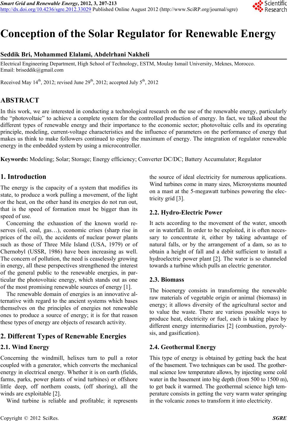
The photovoltaic effect is used in solar cells to con vert
light energy directly from sunlight into electricity
through the production and transport; this can happen
due to a semiconductor material of positive and negative
electrical charges as a result of light.
Copyright © 2012 SciRes. SGRE
Conception of the Solar Regulator for Renewable Energy 209
The photovoltaic effect is the appearance of a potential
difference between the two sides of a semiconductor
junction un der the action of light radi ation.
The photovoltaic conversion is performed by using
photovoltaic cells generally produced crystalline silicon
(Figure 1). If a load is placed across the cell, the elec-
trons of the N zone joining the holes in the P zone via the
external connection, creating a potential difference and
an electric current flows [6].
4.1. Parameters of Solar Radiation Governing
the Functioning of Cells
The sun is a star among many others. It has a diameter of
1,390,000 km, or about 50 times that of Earth. In every
slowness of wave, λ can be associated with a photon of
energy Eph = hv Where h is the constant of Planck (h =
6.62 × 10⁻³⁴ Js) and v the frequency corresponding to the
wavelength (c
n
, where c =3 × 10⁸ m·s–1 speed of
light in the space and n indication of the considered en-
vironment).
Eph is the energy that removes electrons. It is inversely
proportional to the wavelength of the photon.
For an electron bound to the atom (valence band) to
become free in a semiconductor and participates in the
conduction current, you must provide a minimum energy
for it to reach higher energy levels (conduction band ). It
is the energy of the “band gap” Eg in electron volts (eV)
(1 eV = 160.217 × 10⁻²¹ Joule = 44.505 × 10⁻²⁴ Wh).
Each photon must have an energy greater than the en-
ergy Eg (Gap Eg = EC – EV, with EC and EV are respec-
tively the energies of bungs conduction and valence).
4.2. Photovoltaic Cells
Photovoltaic cells are made of “silica”. The latter can be
defined as follows: Silica is found in nature in compact
form (pebbles, quartz vein, for example), or as more or
less fine sand. We also obtained industrially in powder
form.
As a semiconductor, silicon is the main element used
in the manufacture of photovoltaic solar cells.
Figure 1. Principle of operation of a photovoltaic cell.
When a photon with enough energy is absorbed by the
semiconductor, it produces a broken valence bond and
frees an electron creating a “hole” positive [7].
In the darkness, the PV cell operates like a diode. It
does not produce current. However, if connected to an
external source of tension, a current flows ID [8]. A cell is
often modeled by the circuit diagram shown in Figure 2.
s
ph D
sh
VIR
II IR

 (2)
exp 1
s
DS
VIR
II q
AKT







(3)
4.3. Voltage-Current Electrical Characteristics
of a Photovoltaic Panel
The characteristic curve of a PV cell is the variation of
the current it produces according to the voltage across it.
From the short circuit (zero voltage corresponding to the
maximum current product) to open circuit (zero current
for a maximum voltage across the cell). This characteris-
tic I = f(v) turns on the mathematical form from the two
Equations (1) and (2) above as follows:
exp 1
s
s
ph S
sh
VIR VIR
II Iq
AKT R
 

 



(4)
From Equation (3) we draw the variation of the current
I as a function of voltage V, with very high. Rsh is illus-
trated in Figure 3, for a given irradiance and temperature.
Figure 2. Equivalent circuit of a PV cell.
Figure 3. Current-voltage characteristics of photovoltaic
modules E = 1000 W/m2, T = 25˚C.
Copyright © 2012 SciRes. SGRE
Conception of the Solar Regulator for Renewable Energy
210
The area (1) is characterized by the current that re-
mains constant regardless of voltage. In this area, the
PV array operates as a current generator.
The area (2) is characterized by a variation of the
current corresponding to a nearly constant voltage,
and in this region, the generator is similar to a voltage
generator.
The area (3) corresponds to the bend of the characteris-
tic. This is the intermediate region between the two
areas above, and represents the preferred region for
the operation (the optimal point can be determined).
Figure 4 shows the influence of light on the charac-
teristic current—voltage of a photovoltaic module at a
constant temperature.
Note that the voltage VCO varies very slightly depend-
ing on the light, in contrast to the short-circuit ICC in-
creases strongly with light.
Figure 5 shows the influence of temperature on the
current-voltage characteristic of the photovoltaic module
for a given illumination. Note that when the temperature
increases, the open circuit voltage VCO down, while the
short-circuit ICC increases [9].
Figure 5. Influence of temperature for a light, E = 1000
W/m2.
4.4. Efficiency of Photovoltaic Cells
It characterizes the performance efficiency of a system. It
is expressed as the ratio of the energy that the cell prod-
uct, the energy that the panel receives, that is the report:
elecrical light
EE
.
In practice, solar cells convert on ly a portion of the in-
cident energy into electricity.
5. Association of PV Module
In series:
By N identical modules in series, the current in the
branch remains the same and the voltage across the
branch is N times greater than that of a module. As
shown in Figure 6 that c
U, U
c, the voltage
across the cell index “c”. In order to limit the reverse
voltage across the terminals of a module, it is necessary
to place a bypass diode across each module.
U
In parallel:
By N identical modules in parallel, the voltage of the
branch remains the same, and the total curren t is N times
of the current of a module. In Figure 7, we represents the
variation of c
UI
, Ic, Ampere: current across the
cell index “c”. To avoid becoming a receiver module,
there must be a diode in series in each branch.
6. Storage System of Solar Photovoltaic
In a PV system, storage is the conservation of energy
produced by the PV generator, waiting for future use.
Management of solar energy requires envisaged follow-
ing of the conduction of storage and weather that will
address two main functions [10]:
-Provides the installation of electricity when the PV
generator does not produce (at night or in bad weather
for example).
-Provides for the installation of powers greater than
those provided by the PV generator.
Figure 4. Influence of the illumination at T = 25˚C.
Copyright © 2012 SciRes. SGRE
Conception of the Solar Regulator for Renewable Energy
Copyright © 2012 SciRes. SGRE
211
Figure 6. Group of cells in series.
Figure 7. Group of cells in parallel [11].
7. Solar Panels and Profitability
A solar panel is a device designed to recover some en-
ergy from sunlight to convert it into a form of energy
(electric or thermal) used by man.
The yields of the solar panels vary depending on many
factors:
Influence of the angle of incidence.
Interest in photovoltaic solar panels movable relative
to the fixed panels.
Influence of the angle of inclination.
7.1. Influence of the Angle of Incidence
The ang le of inciden ce is the an gle formed by the rays of
the sun and the plane of the panel. The angle of incidence
plays a major role in the yields of the panel.
Thus, the yield is at the maximum when the rays come
perpendicular to the panel. While for an angle of 45˚ for
example, the yield is only 70%. The Figure 8 presents
the performance of panels according to the angle of inci-
dence.
7.2. Interest of Photovoltaic Solar Panels
Movable Relative to the Fixed Panels
During the day, the sun moves continuously, while a
photovoltaic array is fixed in its positioning, losing a
considerable amount of energy that could be available. Figure 8. Graph representing the performance against the
angle of incidence.
Conception of the Solar Regulator for Renewable Energy
212
In a fixed installation which, for optimal performance
is exposed to the south, the energy delivered by PV
modules is maximal only at noon for this if the PV mod-
ules are always oriented towards the sun, as if there the
corresponding condition was constantly at noon, the
power generated is always the maximum.
The photovoltaic modules placed on followers of the
sun have an efficiency that increases significantly com-
pared to fixed installations.
The followers of sun available in our range are moni-
toring the trajectory of the sun (which must be deter-
mined) along with an axis and the latter motorized sea-
sonal manual. They thus generate an increase in the av-
erage output power of about 50% as shown in Figure 9
by the PIC16F876.
7.3. Influence of the Inclination Angle
The “tilt angle” is the angle between the ground plane
and the plane of the panel. However, according to the
seasons, the tilt of the earth varies. To keep power panel
as regular as possible throughout the year, we will keep
the angle of 45˚ south.
8. Rregulators
The controller charge/discharge electronics is fully auto-
matic which are connected to photovoltaic pa nel, battery,
and the end devices of solar electricity.
Regulators can also include other functions such as:
View or indication of battery voltage, state of charge
and various currents.
The alarm relays contacts for transmitting information
indicating a malfunction.
Thresholds of control used to start a rescue group.
Types of regulators
Several types of controllers can be used in photovol-
taic systems. The controller controls the flow of energy.
It must protect the battery against overload (solar) and
deep discharge (user). It must ensure the security and
surveillance installation [12].
Charge controllers are characterized by three main
groups:
-Regulators series: these are the controllers that in-
corporates a switch between the generator and the battery
to stop charging .
The switch load is here in series with the battery as
shown in Figure 10. It opens when the end load is reached.
-Shunt regulators, including the switch bypasses the
solar array at the en d of charge.
All the current passes through the panel battery, as
shown in Figure 11. When the cut off is reached, all the
current passes through the switch. It should be added
imperative this switches a diode between the battery and
not to short-circuit. This diode also acts as blocking cur-
rent flowing from the night up to the battery panel.
-Regulators to search for maximum power point
(MPPT or Maximum Power Point Tracking), which use a
special electronic circuit to continuously extract the col-
lector array maximum power [13].
Converters (i nverters)
Depending on the application, we will often use a
converter to adapt the generated power to the load, since
most of the machines used to operate AC where the need
for an inverter in the PV system.
There are mainly the DC/DC converters that provide
support to a DC voltage different from the voltage gener-
ated by the panels and DC/AC converters th at p r odu ce an
AC voltage for the corresponding expenses [14].
9. Conclusions
Over the study on photovoltaic, we have shown that the
photovoltaic effect is the technology of solar panels con-
stantly evolution of the construction to the installation
Blo c ki n g di o d e
(
)
(+)
Interrupter
Battery
Receiver
Solar
Panel
Unb alla sting
Figure 10. Diagram of a control series.
Solar
Panel
Blocking diode Unballasting
Interrupter
Battery
Receiver
(+)
(
)
Figure 9. Follower-based Microcontroller tracker. Figure 11. Diagram of a shunt regulator [12].
Copyright © 2012 SciRes. SGRE
Conception of the Solar Regulator for Renewable Energy
Copyright © 2012 SciRes. SGRE
213
of a photovoltaic module, which responds to stress spe-
cific techniques, we found that photovoltaic energy re-
newable energy has advantages in terms of the environ-
ment, and operating costs very low is a free energy, gen-
erously and abundantly provided by the sun.
In order to implement the proposed solution in this
paper, an energy storage system using photovoltaic grid
inverters with the advanced modulation technique control
such as modulation staircase, step leader, Delta or PMW
(Pulse Width Modulation) which is developed in our
laboratory. This system offers us the controller devel-
oped the internal components of the inverter controlled
by a programmable memory and will be operated as an
embedded system. The output voltage of the inverter
varies between 180 and 380 volt. This principle will be
the subject of the fut ure p ubl ications an d pa t ent s.
REFERENCES
[1] P. Pernet, Développement de Cellules Solaires en Silicium
Amorphe de Type ‘n.i.p’ Sur Substrats Souples, Thèse
de l’Ecole Polytechnique Fédérale de Lausanne, EPFL,
No. 2303, 2000.
[2] http://www.enrafrique.com/
[3] T. Ackerman and L. Soder, An Overview of Wind En-
ergy—Status 2002,Renewable and Sustainable Energy
Reviews, Vol. 6, No. 1-2, 2002, pp. 67-127.
doi:10.1016/S1364-0321(02)00008-4
[4] M. Orgeret, “Les Piles Solaires, le Composant et ces
Applications, Masson, Amsterdam, 1985.
[5] S. Quoizola, Epitaxie en Phase Vapeur de Silicium Sur
Silicium Mésoporeux Pour Report Sur Substrats Econo-
miques et Application Photovoltaïque Bas Coût, Thèse
EEA, INSA de Lyon, Lyon, 2003, p. 203.
[6] L. Balogh, Implementing Multi-State Charge Algorithm
with the UC3909 Switchmode Lead-Acid Battery Charger
Controller, U-155 Application Note, Unitrode Applica-
tions Handbook, 1997, pp. 3488-3516.
[7] A. Hoque and K. A. Wahid, New Mathematical Model
of a Photovoltaic Generator, Journal of Electrical Engi-
neering, Vol. EE 28, No. 1, 2000.
[8] A. D. Hansen, P. Sorensen, L. H. Hansen and H. Bindner,
“Models for Standard-Alone PV System,” Riso-R-1219
(EN)/SEC-R-12, 2000.
[9] S. Zaamta and A. Dib, “Réalisation d’un Régulateur
Solaire à Base de Microcontrôleur Pour le Contrôle de
l’état de Charge et la Protection des Accumulateurs,”
Janvier, 2009.
[10] N. Achaibou, A. Malek and N. Bacha, “Modèle de Vieil-
lissement des Batteries Plomb Acide Dans l’Installation
PV,” N. Spécial (CHEMSS), 2000, pp. 61-66.
[11] L. Protin and S. Astier, “Convertisseur Photovoltaïques,”
Techniques de l’Ingénieur, Ref D3360-Vol. DAB.
[12] V. Boitier and P. Maussion, “Recherche du Maximum de
Puissance Sur les Générateurs Photovoltaïques,” Université
de Toulouse, Toulouse, 2004.
[13] R. Leyva, I. Queinnec, C. Alonso, A. Cid-Pastor, D. La-
grange and L. Martinez-Salamero, “MPPT of Photovol-
taic Systems Using Extremum Seeking Control,” IEEE
Transaction on Aerospace and Electronic Systems, Vol.
42, No, 1, 2006, pp. 249-258.
doi:10.1109/TAES.2006.1603420
[14] Induction Generators for Variable Speed\Vind Turbines
integrated in a Distribution: Jetwork n, EPE 2003, Tou-
louse.