 Journal of Minerals & Materials Characterization & Engineering, Vol. 11, No.2 pp.133-141, 201 2 jmmce.org Printed in the USA. All rights reserved 133 Study on Weld Quality Ch ar ac te r ist i cs o f Pulsed Current Micro Plasma Arc Weld ing of Inc onel625 Shee ts K. Siva Prasad1*, Ch.Srinivasa Rao2, D.Nageswara Rao3 1 Department of Mechanical Engineering, Anil Neerukonda Institute of Technology & Sciences , Visakhapatnam , INDIA 2Department of Mechanical Engineering, Andhra University, Visakhapatnam, INDIA 3Vice Chancellor, Centurion University, Orissa, INDIA *Corresponding Author Email:kspanits@gmail.com, Contact No: 91-9849212391, Fax No: 91-08933-226395 ABSTRACT Nickel alloys had gathered wide acceptance in the fabrication of components which require high temperature resistance and corrosion resistance, such as metallic bellows used in expansion joints used in aircraft, aerospace and petroleum industry. In the present paper an attempt is made to study various weld quality characteristics like weld bead geometry dimensions, micro hardness, microstructure, grain size and tensile properties of Pulsed Current Micro Plasma Welding of Inconel625sheets. Weld joint was prepared by fusing the two parent metals of Inconel625 sheets. Square butt joint is used and welding was carried out using Pulsed DCEN, without filler wire. Peak current, back current, pulse and pulse width are considered as the main influential input variables during the welding. Key Words: pulsed current, micro plasma arc welding, Inconel625, weld bead geometry, hardness, microstructure, grain size. 1. INTRODUCTION Nickel alloys had gathered wide acceptance in the fabrication of components which require high temperature resistance and corrosion resistance, such as metallic bellows used in expansion joints used in aircraft, aerospace and petroleum industry, in which they are subjected to high temperature and corrosive environment. The present paper focuses on bellow manufacturing in which a thin is to fold round in shape and the edges has to be welded longitudinally.  134 K. Siva Prasad, Ch.Srinivasa Rao Vol.11, No.2 Welding thin sheets is quite different from welding thick sections, because during welding of thin sheets many problems are experienced. These problems are usually linked with heat input. Fusion welding generall y involves joining of metals b y application of heat for melting of metals to be joined. Almost all the conventional arc welding processes offer high heat input, which in turn leads to various problems such as burn through or melt trough, distortion, porosity, buckling warping & twisting of welded sheets, grain coarsening , evaporation of useful elements present in coating of the sheets, joint gap variation during welding, fume generation form coated sheets etc. Use of proper welding process, procedure and technique is one tool to address this issue [1]. Micro Plasma Arc Welding (MPAW) is a good process for joining thin sheet, but it suffers high equipment cost compared to Gas Tungsten Arc Welding. However it is more economical when compare with Laser Beam welding and Electron Beam Welding processes. The plasma welding process was introduced to the welding industry in 1964 as a method of bringing better control to the arc welding process in lower current ranges. Today, plasma retains the original advantages it brought to the industry by providing an advanced level of control and accuracy to produce high quality welds in both miniature and pre precision applications and to provide long electrode life for high production requirements at all levels of amperage. Plasma welding is equally suited to manual and automatic applications. It is used in a variety of joining operations ranging from welding of miniature components to seam welding to high volume production welding and many others. Pulsed current MPAW involves cycling the welding current at selected regular frequency. The maximum current is selected to give adequate penetration and bead contour, while the minimum is set at a level sufficient to maintain a stable arc [2,3]. This permits arc en ergy to be used effectively to fuse a spot of controlled dimensions in a short tim e producing the weld as a series of overlappi ng nu ggets. By co n t rast, in constant current welding, the heat required to melt the base material is supplied only during the peak current pulses allowing the heat to dissi pate int o the base materi al leadin g to narrow er heat affect ed zo ne (HAZ)[4]. Advantages include improved bead contours, greater tolerance to heat sink variations, lower heat input requirements, reduced residual stresses and distortion, refinement of fusion zone microstructure and reduced with of HAZ. There are four independent parameters that influence the process are peak current, back current, pulse and pulse width. From the literature review it was understood that many researchers studied the influence of welding current, arc voltage, welding speed, wire feed rate and magnitude of ion gas flow on front melting width, back melting width and weld reinforcement of Alternating Current Plasma Arc Welding process using Artificial Neural Network- Back Propagation algorithm [5]. Developed an intelligent decision support system for Plasma Arc Welding (PAW) based on fuzzy Radial Basis Function (RBF) neural network [6]. Studied the optimal parameters process of PAW by the Taguchi method with Grey relational analysis. Torch s t an d-off, welding current, welding speed, and plasma gas flow rate (Argon) were chosen as input variables and welding groove root penetration, welding groove width, front-side undercut were measured as output parameters [7]. Adopted central composite rotatable full factorial 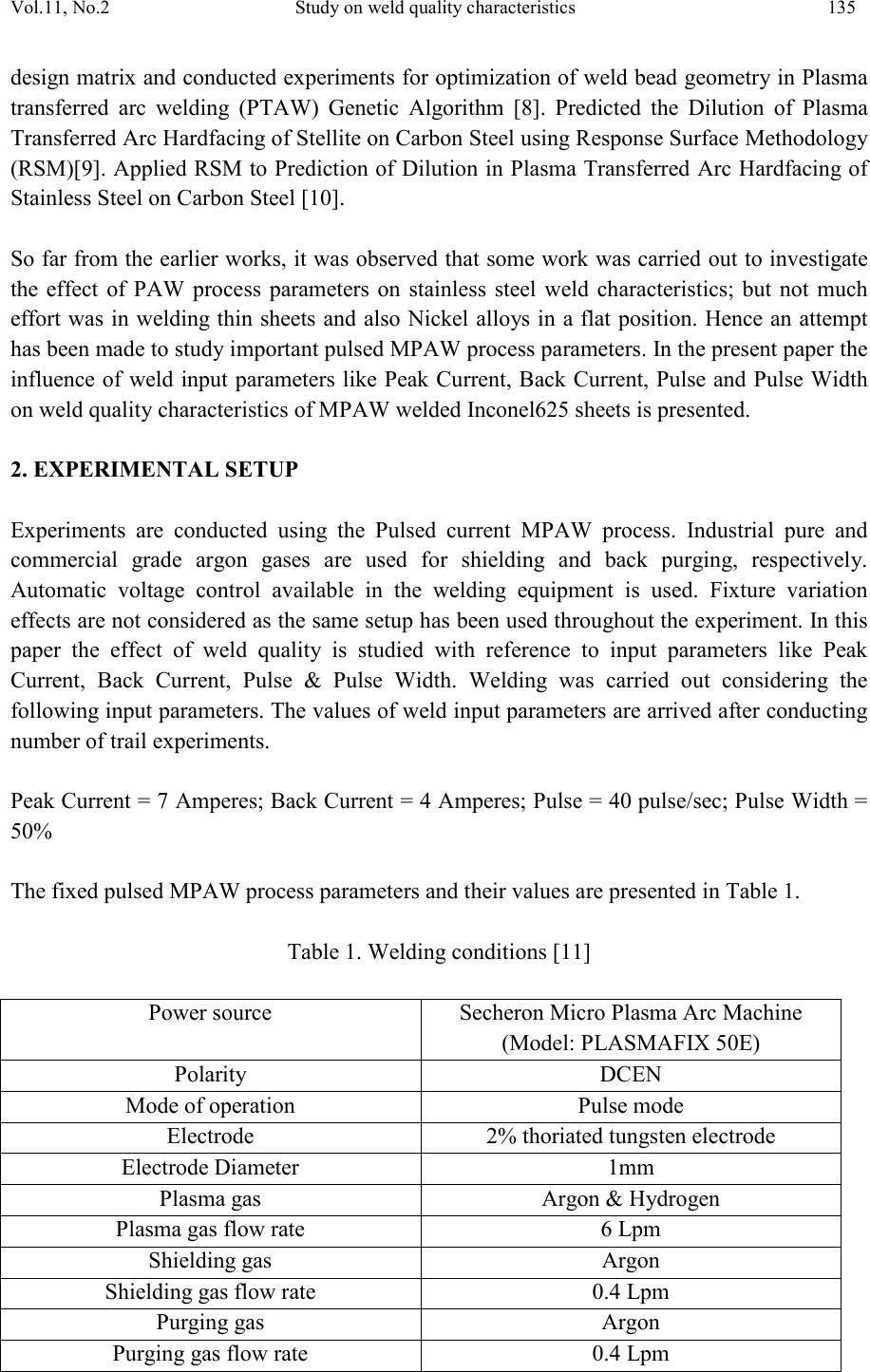 Vol.11, No.2 Study on weld quality characteristic s 135 design matrix and conducted experiments for optimization of weld bead geometry in Plasma transferred arc welding (PTAW) Genetic Algorithm [8]. Predicted the Dilution of Plasma Transfe rred A r c H ardfaci ng o f S tel l it e on Ca rb on St eel usi ng Respon se S urface Methodology (RSM)[9]. Applied RSM to Prediction of Dilution in Plasma Transferred Arc Hardfacing of Stainless Steel on Carbon Steel [10]. So far from the earlier works, it was observed that some work was carried out to investigate the effect of PAW process parameters on stainless steel weld characteristics; but not much effort was in welding thin sheets and also Nickel alloys in a flat position. Hence an attempt has been made to study important pulsed MPAW process parameters. In the present paper the influence of weld input parameters like Peak Current, Back Current, Pulse and Pulse Width on weld quality characteristics of MPAW welded Inconel625 sheets is presented. 2. EXPERIMENTAL SETUP Experiments are conducted using the Pulsed current MPAW process. Industrial pure and commercial grade argon gases are used for shielding and back purging, respectively. Automatic voltage control available in the welding equipment is used. Fixture variation effects are not considered as the same setup has been used throughout the experiment. In this paper the effect of weld quality is studied with reference to input parameters like Peak Current, Back Current, Pulse & Pulse Width. Welding was carried out considering the following input parameters. The values of weld input parameters are arrived after conducting number of trail experiments. Peak Cu rrent = 7 A mperes; Back Curren t = 4 Am peres; Pulse = 40 pulse /sec; Pulse Width = 50% The fixed pulsed MPAW process parameters and their values are presented in Table 1. Table 1. Welding conditions [11] Secheron Micro Plasma Arc Machine (Model: PLASMAFIX 50E) 2% thoriated tungsten electrode Pu r gi ng gas fl o w ra t e  136 K. Siva Prasad, Ch.Srinivasa Rao Vol.11, No.2 Inconel625 of 100×150×0.25 mm as shown in Figure 1 are welded autogenousl y with square butt joint without edge preparation. The chemical composition of Inconel625 was given in Table 2. Table 2 Chemical composition of Inconel625 (weight %) Fig.1 Typical weld joint After preparation of weld joint, visual inspection was carried out to detect surface defects and X-ray was taken to know internal defects like cracks, improper fusion etc. After clearing X- ra y the welded samples were prepared to carry out various tests mentioned in the succeeding paragraphs. 3.MEASUREMENT OF OUTPUT RESPONSES 3.1 Measurement of Weld Pool Geometry Three metallurgical samples were cut from each joint, with the first sample being located at 25mm behind the trailing edge of the crater at the end of the weld and mounted using  Vol.11, No.2 Study on weld quality characteristic s 137 Bakelite. Sample preparation and mounting was done as per ASTM E 3-1 standard. The transverse face of the samples were surface grounded using 120 grit size belt with the help of belt grinder, polished using grade 1/0 (245 mesh size), grade 2/0( 425 mesh size) and grad e 3/0 (515 mesh size) sand paper. The specimens were further polished by using aluminum oxide initially and the by utilizing diamond paste and velvet cloth in a polishing machine. The polished specimens were macro-etched by using Aqua regia solution to reveal the geometry of the weld pool (Fig.2)[11]. Several critical param eters, such as front width, back width, front height and back height of the weld pool geometry (Fig.3) are measured. The weld pool geometry was measured using Metallurgical Microscope (Make: Dewinter Technologie, Model No. DMI-CROWN-II) at 100X magnification. The measured weld pool geometry dimensions are presented in Table 3. Fig.2 Typical weld pool geometry Fig.3 Macrographs of weld pool at 100X Table 3 Weld pool geometry dimensions 3.2 Measurement of Grain Size Three metallurgical samples are cut from each joint, with the first sample being located at 25mm behind the trailing edge of the crater at the end of the weld and mounted using Bakelite. Sample preparation and mounting is done as per ASTM E 3-1 standard. The samples are surface grounded using 120 grit size belt with the help of belt grinder, polished using grade 1/0 (245 mesh size), grade 2/0( 425 mesh size) and grade 3/0 (515 mesh size) (mm) (mm) (mm) (mm)  138 K. Siva Prasad, Ch.Srinivasa Rao Vol.11, No.2 sand paper. The specimens are further polished by using aluminum oxide initially and the by utilizing diamond paste and velvet cloth in a polishing machine. The polished specimens are etched by using Aqua Regia solution to reveal the microstructure as per ASTM E407. Micrographs are taken using metallurgical microscope (Make: Carl Zeiss, Model: Axiovert 40MAT) at 100X magnification. The micrographs of parent metal zone and weld zone are shown in Fig.4 & Fi g. 5. Fig.4 Microstructure of parent metal zone Fig.5 Microstructure of weld zone The grain si z e of p arent met al was p resen ted in Fi g.6. Grai n si z e at th e in terface o f par en t an d weld zone is measured by using Scanning Electron Microscope (SEM) (Make: INCA Penta FETx3, Model: 7573). Fig.7 indicates the grain size at interface of parent metal zone and weld zone. Fig.6 Grain size of parent metal Fig.7 SEM image of grain size of weld fusion zone The average grain size at the weld interface is about 45.772Microns and that of parent metal is about 50 Microns. Smaller grains at interface indicate better strength of weld joint. 3.3 Measurement of Hardn es s  Vol.11, No.2 Study on weld quality characteristic s 139 Vickers’s micro h ardness testin g machine (M ake: MET SUZAWA CO LTD, J APAN, Mo del: MMT-X7) was used to measure the hardness of the weld metal with a 0.5Kg load as per ASTM E384. Average values of three samples of each test case are presented in Table-4. Table 4 The variation of hardness values across the weld joint at 0.3mm interval. hardness value (VHN) 262.5 278.5 268.2 282.5 266.2 258 256.9 250.9 In the above table points 1,2,7,8 are on the parent metal at Heat Affected Zone, points 4, 5 across the Weld Zone and points 3,6 indicates at interface. The variation of hardness across the weld joint is represented in Fig. 8. Fig.8 Variation of Hardness values at an interval of 0.3mm across the weld joint From Fig.8 it is very clear that the hardness values of the weld zone is better than parent metal, which indicates higher strength of the weld joint. 3.4 Measurement of Ultimate Tensile Streng th Three transverse tensile specimens are prepared as per ASTM E8M-04 guidelines and the specimens after wire cut Electro Discharge Machining are shown in Fig.9. Tensile tests are carried out in 100KN computer controlled Universal Testing Machine (ZENON, Model No: WDW-100). The specimen is loaded at a rate of 1.5KN/min as per ASTM specifications, so that the tensile specimens undergo deformation. From the stress strain curve, the ultimate tensile strength of the weld joints is evaluated and the average of three results is presented in Table 4.  140 K. Siva Prasad, Ch.Srinivasa Rao Vol.11, No.2 Fig.9 Tensile specimens Table 5 Tensile properties Yield Strength (MPa)(0.2% offset) % Elongation(50mm gauge length) From Table 5 it is understood that the tensile properties of weld joint and the parent metal are close to each other. 4. CONCLUSIONS Various properties of pulsed current MPAW welded Inconel625 sheets are studied. The study reveals that the sound weld joint is obtained by choosing proper values of peak curr ent, back current, pulse and pulse width as the important process variables. The hardness values of the weld z one are compar ativ ely better than the parent metal zone which indicates better strength of the weld joint. The microstructure of the weld joint indicates the presence of ferrite particles. The grain size at the weld interface is smaller than the parent metal, which reveals that weld zone is stronger than parent metal. The tensile properties of weld joint and the parent metal are close to each other. ACKNOWLEDMENTS We express our sincere thanks to Shri. R.Gopla Krishnan, Director, M/s Metallic Bellows (I) Pvt Ltd, Chennai, INDIA and Andhra University, Visakhapatnam, INDIA for their support to carry out experimentation. REFERENCES [1] Balasub ramanian .M, JayabalanV, BalasubramanianV, “ Effect of process parameters of pulsed current tungsten inert gas welding on weld pool geometry of titanium welds”, Acta Metall.Sin.(Engl. Lett.) Vol.23 No.4pp 312-320 August 2010.  Vol.11, No.2 Study on weld quality characteristic s 141 [2] Balasubramanian.B, Jayabalan.V, Balasubramanian.V, 2006, Optimizing the Pulsed Current Gas Tungsten Arc Welding Parameters, J Mater Sci Technol, 22(6), 821-825. [3] Madusudhana Reddy G, Gokhale A A, Prasad Rao K, 1997, Weld microstructure refinement in a 1441 grade aluminium-lithium alloy, Journal of Material Science, 32(5):4117-4126. [4] Balasubramanian.M, Jayabalan.V and Bal asubraman ian .V, J Mater Sci Technol 22(6) (2006) 821. [5] Zhang.D.K and Niu.J.T , 2000, Application of Artificial Neural Network modeling to Plasma Arc Welding of Aluminum alloys, Journal of Advanced Metallurgical Sciences, Vol.13, No.1, 194-200 . [6] Sheng-Chai Chi, LI-Chang Hsu ,2001, A fuzzy Radial Basis Function Neural Network for Predicting Multiple Quality characteristics of Plasma Arc Welding, IEEE,0-7803- 7078-3/01,2807-2812. [7] Hsiao.Y.F, Tarng.Y.S, and Wang. J, 2008, Huang Optimization of Plasma Arc Welding Parameters by Using the Taguchi Method with the Grey Relational Analysis, Journal of Materials and Manufacturing Processes, 23, 51–58. [8] Siva.K, Muragan.N, Logesh.R, 2008, Optimization of weld bead geometry in Plasma transferred arc hardfacing austenitic stainless steel plates using genetic algorithm, Int J Adv Manuf Technol, Volume 41, Numbers 1-2,24-30. [9] LakshinarayanaA.K, Balasubramanian.V, Varahamoorthy.R and Babu.S, 2008, Predicted the Dilution of Plasma Transferred Arc Hardfacing of Stellite on Carbon Steel using Response Surface Methodology, Metals and Materials International, Vol.14, No.6, 779- 789. [10] Balasubramanian.V, Lakshminarayanan.A.K, Varahamoorthy.R and Babu.S, 2009, Application of Response Surface Methodology to Prediction of Dilution in Plasm a Transf erre d Arc Hardf acin g of S tainl ess S teel on Carbon Steel , S cience Dire ct, Volume 16, Issue 1,44-53. [11] Kondapalli Siva Prasad, Srinivasa Rao.Ch, Nageswara Rao.D, 2011,Prediction of weld pool geometry in pulsed current micro plasma arc welding of SS304l stainless steel sheets, International Transaction Journal of Engineering Management % Applied Sciences & Technologies, Volume 2, No.4, pp 325-336.
|