 Journal of Global Positioning Systems (2002) Vol. 1, No. 2: 73-84 Architecture and Signal Design of the European Satellite Navigation System Galileo - Status Dec. 2002 Guenter W. Hein and Thomas Pany Institute of Geodesy and Navigation, University FAF Munich Received: 23 December 2002 / Accepted: 24 December 2002 Abstract. This paper starts with a brief discussion of the Galileo project status and with a description of the present Galileo architecture (space segment, ground segment, user segment). It focuses on explaining special features compared to the American GPS system. The presentation of the user segment comprises a discussion of the actual Galileo signal structure. The Galileo carrier frequency, modulation scheme and data rate of all 10 navigation signals are described as well as parameters of the search and rescue service. The navigation signals are used to realize three types of open services, the safety of life service, two types of commercial services and the public regulated service. The signal performance in terms of the pseudorange code error due to thermal noise and multipath is discussed as well as interference to and from other radionavigation services broadcasting in the E5 and E6 frequency band. The interoperability and compatibility of Galileo and GPS is realized by a properly chosen signal structures in E5a/L5 and E2-L1- E1 and compatible geodetic and time reference frames. Some new results on reciprocal GPS/Galileo signal degradation due to signal overlay are presented as well as basic requirements on the Galileo code sequences. Key words: GPS, Galileo, Signal Design, European 1 Introduction Based on the communication of the European Commission of February 9, 1999 the satellite navigation system Galileo is presently under development in Europe (European Commission, 1999). The goal on the one hand is to achieve independence of and also an effective supplementation to the GPS. On the other hand the aim is to considerably improve Europe's capability to gain and preserve an important share of the world market for satellite navigation and related applications and services. The strategic and commercial importance of Galileo for Europe is out of discussion. This has repeatedly been confirmed at the European Council conferences in Cologne, Feira, Nice, Stockholm and at last in Laaken on December 14 and 15, 2001 (Belgian EU Presidency, 2001). 2 Status The Galileo project is carried out in co-operation by bodies of the European Union (EU) and the European Space Agency (ESA). In principle it is to be realised in three phases: project definition, development and implementation. The fundamental decision for the realization Galileo was made by the council of the European ministers of transport at March 26, 2002. According to the present planning the development and validation phase should cover the period 2002-2005, the implementation phase 2006-2007, and the operational phase could start in 2008 (Fig. 1). 3 Architecture The main characteristics of the Galileo system architecture can be summarised as follows (Weber et al., 2001): • Independence of other satellite navigation systems • Interoperability with GPS (GLONASS) • Service concept (open, commercial, safety critical, regulated) • Implementation of an Integrity Service (inside/outside Europe) • Independence between Integrity Service and Galileo control System (GCS)  74 Journal of Global Positioning Systems Fig. 1 Galileo master schedule USER SEGMENT IULS ICC IMS Network TTC L-band S- band L -b a nd S-band NSCC OSS Network GALILEO GALILEO GLOBAL COMPONENT GLOBAL COMPONENT NAVIGATION CONTROL & CONSTELLATION MANAGEMENT INTEGRITY DETERMINATION & DISSEMINATION L-band NAV UHF S&R …. REGIONAL REGIONAL COMPONENTS COMPONENTS IULS ICC IMS Network … IULS ICC IMS Network GEO NLES MCC RIMS Network EGNOS LOCAL LOCAL COMPONENTS COMPONENTS … Local MS DATA LINK Local MS DATA LINK COSPAS-SARSAT GROUND SEGMENT SERVICE CENTRES MEO CONSTELLATION UMTS UMTS USER SEGMENT IULS ICC IMS Network TTC L-band S- band L -b a nd S-band NSCC OSS Network GALILEO GALILEO GLOBAL COMPONENT GLOBAL COMPONENT NAVIGATION CONTROL & CONSTELLATION MANAGEMENT INTEGRITY DETERMINATION & DISSEMINATION L-band NAV UHF S&R …. REGIONAL REGIONAL COMPONENTS COMPONENTS REGIONAL REGIONAL COMPONENTS COMPONENTS IULS ICC IMS Network … IULS ICC IMS Network GEO NLES MCC RIMS Network NLES MCC RIMS Network EGNOS LOCAL LOCAL COMPONENTS COMPONENTS … Local MS DATA LINK Local MS DATA LINK … Local MS DATA LINK Local MS DATA LINK COSPAS-SARSAT GROUND SEGMENT SERVICE CENTRES MEO CONSTELLATION UMTS UMTS Fig. 2 Overview of the Galileo system architecture • Global services (SAR, and referred to navigation data related services) • Global location and time dissemination on the basis of a global constellation • Regional components (Monitor and uplink stations) • Integration with regional systems (e.g. EGNOS) • Integration with local (differential etc.) systems • Compatibility with future mobile radio networks (UMTS)  Hein & Pany: Architecture and Signal Design of Galileo - Status Dec. 2002 75 It can be seen from Fig. 2 that the main extension of Galileo compared to GPS consists in the implementation of a global / regional segment for integrity monitoring. The goal is to assist the safety critical aircraft navigation (landing approach CAT I) and to locate and guide railway trains (Train control). Space Segment Fig. 3 Galileo space segment The space segment of Galileo is intended to consist of a total 30 Mean Earth Orbiting (MEO) satellites configured as walker 27/3/1 (+ 3 replacement satellites) constellation (Benedicto et al., 2000), i.e. distributed over three orbital planes (Fig. 3). The altitude is 23616 km, and the inclination is 56°. The satellite design (Fig. 4) is based on already carried out precursor programs (e.g. GLOBALSTAR) including critical payload technologies, which are developed in accompanying ESA programs. The Galileo satellite has a mass of 625 kg, generates a primary power of 1500 W and belongs with dimensions of 2.7 x 1.2 x 1.1 m3; to the category mini-satellites. The satellite comprises all standard systems for orbit and attitude control, thermal control, etc. Unlike GPS, also Laser retro-reflectors will be integrated in order to assist the orbit determination by satellite Laser ranging. Attitude Sensors L-Band Antenna Laser Retro – Reflector Attitude Sensors L-Band Antenna Laser Retro – Reflector Fig. 4 Galileo satellite with retracted solar generators The navigation payload is the heart of the Galileo satellite. The payload is a regenerative transponder with modern digital and semiconductor technology applied to the essential subsystems. It consists of atomic clocks (Clock Monitoring and Control Unit), the signal generator (Navigation Signal Generation Unit) with CPU, the frequency generator (FPGU), the output amplifier (Solid State Power Amplifier) and the L-band antenna sub-system. As atomic clocks two Rubidium standards (5 10 -13 over 100 s) and two space-borne H-Masers (5 10 -14 over 10000 s) are to be used. Ground Segment As already outlined, the Galileo ground segment comprises the control segment for operation as well as orbit and time determination (GCS or Ground Control Segment) and the system for integrity monitoring (IDS or Integrity Determination System). The number of elements in the GCS and the IDS are under further investigation in the present definition phase. The GCS will consist of about 12-15 reference stations, 5 up-link stations and two control centres. The IDS for Europe will include 16-20 monitor stations, three up-link stations for integrity data and two central stations for integrity computations. In the European area the integration with the EGNOS ground segment plays an important role. User Segment Like with GPS the Galileo user segment consists of all users on land, on water, in the air and in space. Fig. 5 shows the shares of various application on the European GNSS market as predicted for 2005 (volume 8 billion EURO). Car Navigation 23% Mobile Phones 73% Aviation 1% Fleet Mgt 1% Augmentation 1% Leisure 1% Surveying 1% Car Navigation 23% Mobile Phones 73% Aviation 1% Fleet Mgt 1% Augmentation 1% Leisure 1% Surveying 1% Car Navigation 23% Mobile Phones 73% Aviation 1% Fleet Mgt 1% Augmentation 1% Leisure 1% Surveying 1% Fig. 5 Prediction of the European GNSS market for 2005 Tab. 1 displays the requirements on the Galileo performance parameters (elevation mask, accuracy, coverage, availability, integrity) as posed by two basically different applications. The requirements for  76 Journal of Global Positioning Systems Fig. 6 Galileo ground segment (example) safety critical applications are identical with the aviation specifications for the precise landing approach of CAT I. In case of the requirements from the mass market it is important that these apply for elevation masks above 25°. This accounts for the specific conditions of land navigation in urban areas (obstructions, multi-path). Tab. 1 Selected requirements on Galileo parameter mass market safety critical elevation mask 25° 5° accuracy (95 %) 10 m horizontal 4 m vertical coverage global global availability > 70 % > 99 % integrity not required mandatory (6 s, 10 -7 ) 4 The Galileo Frequency And Signal Baseline A tentative Galileo frequency and signal plan was presented at the ION GPS-2001 (Hein et al, 2001) which became meanwhile the baseline for the development of Europe´s satellite navigation system. Over the last months several modifications took place leading to a refined signal structure. The main changes and add-ons are described in the following and after that the complete signal structure will be outlined. Recent Developments In the lower L-band (i.e. E5a and E5b) the central frequency for E5b was moved to 1207.140 MHz in order to minimize possible interference from the Joint Tactical Information Distribution System (JTIDS) and the Multifunctional Information Distribution System (MIDS). All signals on E5a and E5b are using chip rates of 10 Mcps. The modulation for that band is still being optimized with the possibility to process very wideband signals by jointly using the E5a and E5b bands. This joint use of the bands has the potential to offer enormous accuracy for precise positioning with a low multipath. Data rates have also been fixed. In the middle (i.e. E6) and upper (i.e. E2-L1-E1) L-band data and chip rates were also defined as well as Search and Rescue (SAR) up- and downlink frequencies. Extensive interference considerations took place in E5a/E5b concerning Distance Measuring Equipment (DME), the Tactical Air Navigation System (TACAN) and the Galileo overlay on GPS L5; in E6 concerning the mutual interference to/from radars and in E2-L1-E1 frequencies with regard to the Galileo overlay on GPS L1. The EC Signal Task Force and ESA have refined criteria for the code selection and have as well formulated the requirements on each frequency. Reference codes have been selected allowing initial assessments. Parallel investigations are on-going addressing alternate solutions for the Galileo codes and targeting improved performances, see e.g. (Pratt, 2002). Frequencies and Signals Galileo will provide 10 navigation signals in Right Hand Circular Polarization (RHCP) in the frequency ranges 1164-1215 MHz (E5a and E5b), 1215-1300 MHz (E6) and 1559-1592 MHz (E2-L1-E11), which are part of the Radio Navigation Satellite Service (RNSS) allocation. An overview is shown in Fig. 7, indicating the type of modulation, the chip rate and the data rate for each signal. The carrier frequencies, as well as the frequency bands 1 The frequency band E2-L1-E1 is sometimes denoted as L1 for convenience.  Hein & Pany: Architecture and Signal Design of Galileo - Status Dec. 2002 77 Pilot (*) 1207.140 MHz 1164 MHz 1164 MHz 1214 MHz 1214 MHz 1260 MHz 1260 MHz 1300 MHz 1300 MHz 1189 MHz 1189 MHz (*) 1176.45 MHz 1278.75 MHz 1544 MHz 1544.2 MHz 1559 MHz 1587 MHz 1591 MHz 1563 MHz 1575.42 MHz OS Data 10 Mcps Data 50 sps Pilot Channel CS Data BPSK(5 Mcps) Data 1000 sps Pilot Channel OS/SOL/CS Data 10 Mcps Data 250 sps Pilot Channel PRS Data BOC(10,5) Data 300 sps OS/SOL/CS Data BOC(2,2) Data 250 sps Pilot Channel PRS Data BOC(n,m) Data 300 sps OS Data 10 Mcps Data 50 sps Pilot Channel CS Data BPSK(5 Mcps) Data 1000 sps Pilot Channel OS/SOL/CS Data 10 Mcps Data 250 sps Pilot Channel PRS Data BOC(10,5) Data 300 sps OS/SOL/CS Data BOC(2,2) Data 250 sps Pilot Channel PRS Data BOC(n,m) Data 300 sps Pilot Pilot Pilot Frequenc y E5a E5b E6 L1E2 E1 PRS Data BOC(10,5) Data TBS sps PRS Data BOC(n,m) Data TBS sps Galileo Assigned Frequency Band GPS L5 Band Glonass L3 Band Carrier Frequencies (*) In case of separate modulation of E5a and E5b signals GPS L1 Band SAR DownlinkSignals Accessible to all Users, with data partly encrypted Signals to which access is restricted through the use of encryption for Ranging Codes and data Signals to which access is controlled through the use of encryption for Ranging Codes and data Fig. 7 Galileo frequency spectrum that are common to GPS or to GLONASS are also highlighted. All the Galileo satellites will share the same nominal frequency, making use of Code Division Multiple Access (CDMA) compatible with the GPS approach. Six signals, including three data-less channels, so-called pilot tones (ranging codes not modulated by data), are accessible to all Galileo Users on the E5a, E5b and L1 carrier frequencies for Open Services (OS) and Safety-of- life Services (SoL). Two signals on E6 with encrypted ranging codes, including one data-less channel are accessible only to some dedicated users that gain access through a given Commercial Service (CS) provider. Finally, two signals (one in E6 band and one in E2-L1-E1 band) with encrypted ranging codes and data are accessible to authorized users of the Public Regulated Service (PRS). Tab. 2 Main Galileo navigation signal parameters freq. Bands E5a E5b E6 E2-L1-E1 Channel I Q I Q A B C A B C modulation type being optimized [AltBOC(15,10) or two QPSK2] A Æ BOC(10,5) B Æ BPSK3(5) C Æ BPSK(5) A Æ flexible BOC(n,m) B Æ BOC(2,2) C Æ BOC(2,2) chip rates 10 Mcps 10 Mcps 10 Mcps 10 Mcps 5.115 Mcps 5.115 Mcps 5.115 Mcps m × 1.023 Mcps 2.046 Mcps 2.046 Mcps symbol rates 50 sps N/A 250 sps N/A TBD sps 1000 sps N/A TBD sps 250 sps N/A user min. received power at 10o elevation -158 dBW -158 dBW -158 dBW -158 dBW -155 dBW -158 dBW -158 dBW -155 dBW -158 dBW -158 dBW 2 Quadrature Phase Shift Keying 3 Binary Phase Shift Keying  78 Journal of Global Positioning Systems A ½ rate Viterbi convolutional coding scheme is used for all the transmitted signals. Four different types of data are carried by the different Galileo signals: • OS data, which are transmitted on the E5a, E5b and E2-L1-E1 carrier frequencies. OS data are accessible to all users and include mainly navigation data and SAR data. • CS data transmitted on the E5b, E6 and E2-L1-E1 carriers. All CS data are encrypted and are provided by some service providers that interface with the Galileo Control Centre. Access to those commercial data is provided directly to the users by the service providers. • SoL data that include mainly integrity and Signal in Space Accuracy (SISA) data. Access to the integrity data may be controlled. • PRS data, transmitted on E6 and L1 carrier frequencies. A synthesis of the data mapping on Galileo signals is provided in Tab. 2. Modulation Schemes Given the frequency plan defined earlier and the target services based on the Galileo signals, the type of modulation of the various Galileo carriers are resulting from a compromise between the following criteria: • Minimization of the implementation losses in the Galileo satellites, making use of the current state of the art of the related equipments. • Maximization of the power efficiency in the Galileo satellites. • Minimization of the level of interference induced by the Galileo signals in GPS receivers. • Optimization of the performance and associated complexity of future Galileo user receivers. The modulation chosen for each of the Galileo carrier frequency is presented in the following subsections. For the E5 band in particular, the trade-off analysis is on going between two alternate solutions that will be both described. The main modulation parameters for Galileo signals are summarized on the Tab. 2. The following notation is used: - CX Y(t) is the ranging code on the Y channel (“Y” stands for I or Q for two channels signals, or A, B or C for three channels signals) of the X carrier frequency (“X” stands for E5a, E5b, E6 or L1). - DX Y(t) is the data signal on the Y channel in the X frequency band. - FX, is the carrier frequency in the X frequency band. - ScX Y(t) is the rectangular subcarrier on the Y channel in the X frequency band. - m is a modulation index, associated to the modified Hexaphase modulation. Modulation of the E5 Carrier The modulation of E5 will be done according to one of the following schemes: A. Two QPSK(10) signals will be generated coherently and transmitted through two separate wideband channels on E5a and E5b respectively. The two separate E5a and E5b signals will be amplified separately and combined in RF through an output multiplexer (OMUX) before transmission at the 1176.45 MHz and 1207.14 MHz respective carrier frequencies. B. One single wideband signal generated following a modified BOC(15,10)4 modulation called AltBOC(15,10) modulation. This signal is then amplified through a very wideband amplifier before transmission at the 1191.795 MHz carrier frequencies. In case A the E5 signal can be written as: () ()()( )()() ()()()() () () tFtCtFtDtC tFtCtFtDtC tS bE Q bEbE I bE I bE aE Q aEaE I aE I aE E..2sin..2cos. ..2sin..2cos. 55555 55555 5ππ ππ ×−×+ ×−× = The modulation in case B is a new modulation concept which main interest is that it combines the two signals (E5a and E5b) in a composite constant envelope signal which can then be injected through a very wideband channel. This wideband signal then can then be exploited in the receivers. A detailed description of the AltBOC modulation can be found in (Ries et al., 2002b). Implementation trade-offs and performance comparison between the processing of the very wideband BOC(15,10)-like signal and the joint processing of two separate QPSK signals of 10 Mcps on E5a and E5b is on- going. Modulation of the E6 Carrier The E6 signal contains three channels that are transmitted at the same E6 carrier frequency. The multiplexing scheme between the three carriers is a major point under consideration today, which shall be carefully optimized. This optimization process shall take into account payload 4 BOC( fs, fc), denotes a Binary Offset Carrier modulation with a subcarrier frequency fs and a code rate fc.  Hein & Pany: Architecture and Signal Design of Galileo - Status Dec. 2002 79 and receivers implementation complexity and associated performances (including compatibility aspects). The investigated solutions are time multiplexing and a modified Hexaphase modulation (so-called Interplex modulation). The modified Hexaphase is taken as baseline but the final selection process is on going between those two potential solutions. A QPSK signal resulting from the combination of two channels is phase modulated with the third channel. The modulation index m is used to set the relative power between the three channels. Using a Hexaphase modulation, the E6 signal can be written: () () ()() ()()() () () [ )..2sin())sin().(...)cos(.. )..2cos())sin(.)cos().(.. 6666666 66666 6tFmtSctCtCtCmtDtC tFmtCmtSctDtC tS EE C E B E A E B E B E E C EE A E A E Eπ π ×+− ×− = ] × To be consistent with the relative powers required between the three channels, a value of m=0.6155 has been chosen for the modulation index. Modulation of the E2-L1-E1 Carrier In the same way than the E6 signal, the L1 signal contains three channels that are transmitted at the same L1 carrier frequency using a modified Hexaphase modulation. Time multiplexing is also being analyzed. The E2-L1-E1 signal, using a Hexaphase modulation, can be written: () () ()() ()()() ()() 11 1 111 1 11 111 111 .. ().cos(). ()sin())cos(2..) .. ()cos()...().sin())sin(2..) AAa Cb LL L LLL LBB bABCa LL LLL LLL CtDtSctmCtSct mFt St CtDtSctmCtCtCtSct mFt π π −× = −+ The same modulation index of m=0.6155 is used. 5 Galileo Spreading Codes The pseudo random noise (PRN) code sequences used for the Galileo navigation signals determine important properties of the system. Therefore a careful selection of Galileo code design parameters is necessary. These parameters include the code length and its relation to the data rate and the auto- and cross-correlation properties of the code sequences. The performance of the Galileo codes is also given by the cold start acquisition time. A first set of reference codes is being retained that offer a good compromise between acquisition time and protection against interference. These codes are based on shift-registered codes, which will be generated on-board. The reference ranging codes are constructed tiered codes, consisting in a short duration primary code modulated by a long duration secondary code. The resulting code then has an equivalent duration equal to the one of the long duration secondary codes. The primary codes are based on classical gold codes with register length up to 25. The secondary codes are given by predefined sequences of length up to a 100. Further alternative codes are presently investigated (Pratt, 2002) and flexibility in the on-board implementation is being considered to foresee the generation of other types of codes. Code Length The code length for Galileo channels carrying a navigation data message shall fit within one symbol in order to have no code ambiguity. The resulting code lengths are shown in Tab. 3. Tab. 3 Spreading codes main characteristics channels types of data code sequence duration primary code length secondary code length E5aI OS 20 ms 10230 20 E5aQ no data 100 ms 10230 100 E5bI OS/CS/SoL 4 ms 10230 4 E5bQ no data 100 ms 10230 100 E6A PRS TBD - - E6B CS 1 ms 8184 - E6C no data 100 ms 10230 50 L1A PRS TBD - - L1B OS/CS/SoL 4 ms 8184 - L1C OS/CS/SoL 8124 25 For the data-less channels, the basic approach is to consider long codes of 20 ms length. Alternate solutions are however being investigated. The first one is to follow a GPS L5 approach consisting of a short code of 1 ms length equally long to the code in quadrature. The second one is to have a much longer code, which could have duration of 0.7 s as in the case of the L2 civil signal. Especially in the case of E5a and E5b it would be useful to determine the data-less code length by analyzing the susceptibility against local interference. Auto- and Cross-Correlation Properties The cross-correlation properties (interference) are partly determined by the actual code sequences as will be discussed below. Especially for E5a careful code selection is necessary because at this frequency band Galileo and GPS use the same modulation scheme and code rate. 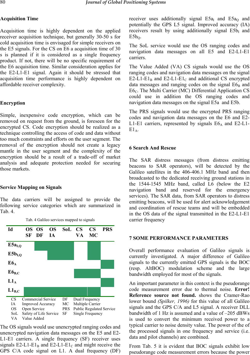 80 Journal of Global Positioning Systems Acquisition Time Acquisition time is highly dependent on the applied receiver acquisition technique, but generally 30-50 s for cold acquisition time is envisaged for simple receivers on the E5 signals. For the CS on E6 a acquisition time of 30 s is planned if it is considered as a single frequency product. If not, there will be no specific requirement of the E6 acquisition time. Similar consideration applies for the E2-L1-E1 signal. Again it should be stressed that acquisition time performance is highly dependent on affordable receiver complexity. Encryption Simple, inexpensive code encryption, which can be removed on request from the ground, is foreseen for the encrypted CS. Code encryption should be realized as a technique controlling the access of code and data without too much constraints and efforts on the user segment. The removal of the encryption should not create a legacy mantle in the user segment and the complexity of the encryption should be a result of a trade-off of market analysis and adequate protection needed for securing those markets. Service Mapping on Signals The data carriers will be assigned to provide the following service categories which are summarized in Tab. 4. Tab. 4 Galileo services mapped to signals Id OS SF OS DF OS IA SoL CS VA CS MC PRS E5aI,Q E5bI,Q E6A E6B,C L1A L1B,C CS Commercial Service DF Dual Frequency IA Improved Accuracy MC Multiple Carrier OS Open Service PRS Public Regulated Service SoL Safety of Life Service SF Single Frequency VA Value Added The OS signals would use unencrypted ranging codes and unencrypted navigation data messages on the E5 and E2- L1-E1 carriers. A single frequency (SF) receiver uses signals E2-L1-E1B and E2-L1-E1C and might receive the GPS C/A code signal on L1. A dual frequency (DF) receiver uses additionally signal E5aI and E5aQ and potentially the GPS L5 signal. Improved accuracy (IA) receivers result by using additionally signal E5bI and E5bQ. The SoL service would use the OS ranging codes and navigation data messages on all E5 and E2-L1-E1 carriers. The Value Added (VA) CS signals would use the OS ranging codes and navigation data messages on the signal E2-L1-E1B and E2-L1-E1C and additional CS encrypted data messages and ranging codes on the signal E6B and E6C. The Multi Carrier (MC) Differential Application CS could use in addition the OS ranging codes and navigation data messages on the signal E5a and E5b. The PRS signals would use the encrypted PRS ranging codes and navigation data messages on the E6 and E2- L1-E1 carriers, represented by signals E6A and E2-L1- E1A. 6 Search And Rescue The SAR distress messages (from distress emitting beacons to SAR operators), will be detected by the Galileo satellites in the 406-406.1 MHz band and then broadcasted to the dedicated receiving ground stations in the 1544-1545 MHz band, called L6 (below the E2 navigation band and reserved for the emergency services). The SAR data, from SAR operators to distress emitting beacons, will be used for alert acknowledgement and coordination of rescue teams and will be embedded in the OS data of the signal transmitted in the E2-L1-E1 carrier frequency 7 SOME PERFORMANCE PARAMETERS Overall performance evaluation of Galileo signals is currently investigated. A major difference of Galileo signals to the currently emitted GPS signals is the BOC (resp. AltBOC) modulation scheme and the large bandwidth employed for most of the signals. An important parameter in this context is the pseudorange code measurement error due to thermal noise. Error! Reference source not found. shows the Cramer-Rao lower bound (Spilker, 1996) for this value of all Galileo signals and the GPS C/A and L5 signal. A receiver DLL bandwidth of 1 Hz is assumed and a value of –205 dBWs is used to convert the minimum received power to a typical carrier to noise density value. The power of the of the processed signals in one frequency and service (i.e. data and pilot channels) are combined. From Tab. 5 it is evident that BOC signals exhibit low pseudorange code measurement errors because the power  Hein & Pany: Architecture and Signal Design of Galileo - Status Dec. 2002 81 spectral density is located at the lower and upper boundary of the frequency spectrum and not at the center as it is for BPSK or QPSK signals. Tab. 5 Code accuracy due to thermal noise processed signals modulation power [dBW] bandw. [MHz] code noise [cm] E5a or E5b BPSK(10) -155 24 4.6 E5a+E5b, non-coh. BPSK(10) -152 24 3.2 E5a+E5b, coh. BOC(15,10) -152 51 0.8 E6A BOC(10,5) -155 40 1.7 E6B+E6C BPSK(5) -155 24 6.2 L1A BOC(14,2) -155 32 1.2 L1B+L1C BOC(2,2) -155 24 5.5 GPS C/A BPSK(1) -160 24 23.9 GPS L5 BPSK(10) -154 24 4.1 This also implies that the autocorrelation function of BOC signals shows several peaks and dedicated algorithms must be implemented in the receiver to track the correct (central) peak. Tracking of BOC signals is discussed in (Betz, 1999 and Pany et al. 2002). Large signal bandwidths allow the use of a very narrow correlator spacing. Low thermal noise and low code multipath are the resulting benefits. Code multipath envelopes differ significantly if BOC and BPSK signals are compared as shown in Fig. 8 and Fig. 9. For these figures a coherent early minus late code discriminator is used. A common discriminator spacing of d=1/14 is chosen to allow for visual comparisons of all signals and to track the central peak of the BOC(14,2) signal. The multipath signal is -3 dB weaker than the direct signal. Note that typical multipath amplitudes are in the range between -7 and -10 dB. Fig. 8 Multipath error envelope, green: BOC(15,10)5, black: BOC(10,5), blue: BPSK(10), red: BPSK(5). The figures show that multipath performances of BOC signals is generally better than for BPSK signals but a detailed investigations taking into account multipath mitigation algorithms and dedicated multipath scenarios will give more insight (Winkel, 2002). 5 A standard BOC modulation scheme was used. Fig. 9 Multipath error envelope, black: BOC(2,2), red: BOC(14,2), blue: BPSK(1). If E5a and E5b are tracked coherently, this results in an extremely low code tracking error due to thermal noise (cf. 3rd line of Error! Reference source not found.) and good multipath mitigation performance. If the E5a and E5b are tracked separately (non-coherently) as QPSK(10) signals and combined after correlation (i.e. averaging of E5a and E5b pseudoranges) the performance gain is much less (cf. 2nd line of Tab. 5). 8 Recent Results Of Interference Studies The use of the frequency range 960-1215 MHz, containing the lower L-band E5a and E5b, by aeronautical radionavigation services is reserved on a worldwide basis to airborne electronic aids to air navigation and any directly associated ground-based facilities and, on a primary basis, to radionavigation satellite services. This multiple allocation causes interference, which has to be assessed carefully to allow the usage of GPS/Galileo navigation signals for safety critical applications. Discussion on interference assessment of DME/TACAN, JTIDS/MIDS and radar out of band radiation over L5, E5a and E5b have been conducted since several years. Interference due to these ground-based sources increases with altitude since more interfering signals are received. The sensitive parameter in this context is the acquisition threshold having limited margins to cope with interference of 5.8 dB for GPS L5, 4.8 dB for E5a and 3.3 dB for E5b. Tracking threshold and data demodulation threshold values are a few dB higher. A standard time domain pulse blanking receiver and advanced signal processing is assumed to be used (Hegarty et al., 2000). It should be noted that in contrast to the US, Europe does not plan at present to re-allocate certain DMEs to circumvent this problem. 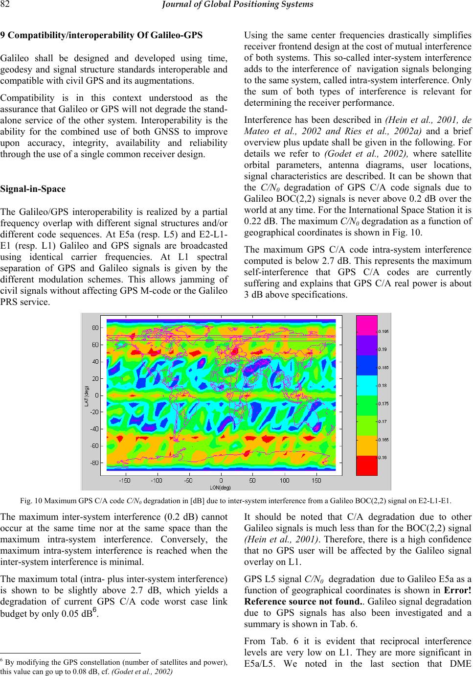 82 Journal of Global Positioning Systems 9 Compatibility/interoperability Of Galileo-GPS Galileo shall be designed and developed using time, geodesy and signal structure standards interoperable and compatible with civil GPS and its augmentations. Compatibility is in this context understood as the assurance that Galileo or GPS will not degrade the stand- alone service of the other system. Interoperability is the ability for the combined use of both GNSS to improve upon accuracy, integrity, availability and reliability through the use of a single common receiver design. Signal-in-Space The Galileo/GPS interoperability is realized by a partial frequency overlap with different signal structures and/or different code sequences. At E5a (resp. L5) and E2-L1- E1 (resp. L1) Galileo and GPS signals are broadcasted using identical carrier frequencies. At L1 spectral separation of GPS and Galileo signals is given by the different modulation schemes. This allows jamming of civil signals without affecting GPS M-code or the Galileo PRS service. Using the same center frequencies drastically simplifies receiver frontend design at the cost of mutual interference of both systems. This so-called inter-system interference adds to the interference of navigation signals belonging to the same system, called intra-system interference. Only the sum of both types of interference is relevant for determining the receiver performance. Interference has been described in (Hein et al., 2001, de Mateo et al., 2002 and Ries et al., 2002a) and a brief overview plus update shall be given in the following. For details we refer to (Godet et al., 2002), where satellite orbital parameters, antenna diagrams, user locations, signal characteristics are described. It can be shown that the C/N0 degradation of GPS C/A code signals due to Galileo BOC(2,2) signals is never above 0.2 dB over the world at any time. For the International Space Station it is 0.22 dB. The maximum C/N0 degradation as a function of geographical coordinates is shown in Fig. 10. The maximum GPS C/A code intra-system interference computed is below 2.7 dB. This represents the maximum self-interference that GPS C/A codes are currently suffering and explains that GPS C/A real power is about 3 dB above specifications. Fig. 10 Maximum GPS C/A code C/N0 degradation in [dB] due to inter-system interference from a Galileo BOC(2,2) signal on E2-L1-E1. The maximum inter-system interference (0.2 dB) cannot occur at the same time nor at the same space than the maximum intra-system interference. Conversely, the maximum intra-system interference is reached when the inter-system interference is minimal. The maximum total (intra- plus inter-system interference) is shown to be slightly above 2.7 dB, which yields a degradation of current GPS C/A code worst case link budget by only 0.05 dB6. 6 By modifying the GPS constellation (number of satellites and power), this value can go up to 0.08 dB, cf. (Godet et al., 2002) It should be noted that C/A degradation due to other Galileo signals is much less than for the BOC(2,2) signal (Hein et al., 2001). Therefore, there is a high confidence that no GPS user will be affected by the Galileo signal overlay on L1. GPS L5 signal C/N0 degradation due to Galileo E5a as a function of geographical coordinates is shown in Error! Reference source not found.. Galileo signal degradation due to GPS signals has also been investigated and a summary is shown in Tab. 6. From Tab. 6 it is evident that reciprocal interference levels are very low on L1. They are more significant in E5a/L5. We noted in the last section that DME  Hein & Pany: Architecture and Signal Design of Galileo - Status Dec. 2002 83 interference of E5a and L5 signal leaves only a small margin to civil aviation users at high altitudes, especially over Europe where no DME reallocation is planned. Therefore GPS degradation on Galileo in E5a must be carefully assessed in future work. Tab. 6 Reciprocal level of interference (worst case link budget degradation / inter-system C/N0 degradation) frequency band GPS induced interference on Galileo Galileo induced interference on GPS L1 0.03 dB/0.09 dB 0.05 dB/0.2 dB E5a/L5 0.5 dB/0.8 dB 0.2 dB/0.4 dB Geodetic Coordinate Reference Frame For the Galileo coordinate reference system international civilian standards will be adopted. However, for various reasons the realization of the Galileo coordinate and time reference frame should be based on stations and clocks different from those of GPS. These reasons include independence and vulnerability of both systems, allowing one system to act as a backup solution for the other. The Galileo Terrestrial Reference Frame (GTRF) shall be in practical terms an independent realization of the International Terrestrial Reference System (ITRS) established by the Central Bureau of the International Earth Rotation Service (IERS). The ITRF is based on a set of station coordinates and velocities derived from observations of VLBI, LLR, SLR, GPS and DORIS. A reduction of the individual coordinates to a common reference epoch considering their station velocity models is performed using fixed plate motion models or estimated velocity fields. GPS uses WGS84 as coordinate reference frame, practically also a realization of the ITRS, realized by the coordinates of the GPS control stations. The differences between WGS84 and the GTRF are expected to be only a few cm. This implies for the interoperability of both GNSS systems that the WGS84 and GTRF will be identical within the accuracy of both realizations (i.e. coordinate reference frames are compatible). This accuracy is sufficient for navigation and most other user requirements and the remaining discrepancies in the 2 cm level are only of interest for research in geosciences. Transformation parameters can be provided by a Galileo external Geodetic Reference Service Provider – if needed at all. At the moment it is not foreseen to put such information in the navigation data message. A coordinate reference frame has to be accomplished by an Earth’s gravity model. For example, the WGS84 uses a spherical harmonic expansion of the gravity potential up to the order and degree 360. For Galileo a similar model must be considered. In that context the European satellite gravity missions GOCE and CHAMP as well as the American mission GRACE are of importance. Time Reference Frame The Galileo System Time (GST) shall be a continuous coordinate time scale steered towards the International Atomic Time (TAI) with an offset of less then 33 ns. The GST limits, expressed as a time offset relative to TAI, 95% of the time over any yearly time interval, should be 50 ns. The difference between GST and TAI and between GST and UTC(Pred) shall be broadcasted to the users via the signal-in-space of each service. The offset of the GST with respect to the GPS system time is monitored in the Galileo ground segment and the offset is eventually broadcasted to the user. The offset might also be estimated in the user receiver with very high accuracy by spending just one satellite observation – the accuracy is (probably) higher than that one (eventually) broadcasted. Thus, broadcasting might be not necessary for the general navigation user. Interoperability Summary The Galileo system follows international recommendations for steering of its time and coordinate references (UTC and ITRF). This itself enables a possible high level of interoperability in case GPS follows the same, very reasonable, rules. Acknowledgements The article is based on work of the European Commission Signal Task Force (Hein et al., 2002). The underlying investigations were supported by many European national space agencies like e. g. Centre National d´Etudes Spatiales (France), Deutsches Zentrum für Luft- und Raumfahrt (DLR, Germany) and Defence Science and Technology Laboratory (United Kingdom) Their support and contribution is acknowledged. References Belgian EU Presidency (2001): European Council of Laeken, Presidency Conclusions, No. 33, Laeken, December 14-15, 2001. Benedicto, J., S. Dinwiddy, G. Gatti, R. Lucas and M. Lugert (2000): GALILEO: Satellite Design and Technology Developments, European Space Agency, Noordwijk, November 2000. Betz, J. (1999): The Offset Carrier Modulation for GPS Modernization, Proc. of ION 1999 National Technical Meeting, San Diego, January 1999.  84 Journal of Global Positioning Systems European Commission (1999): GALILEO, Involving Europe in a New Generation of Satellite Navigation Services, Communication 54, Brussels, February 9, 1999. Godet, J., J.C. de Mateo, P. Erhard and O. Nouvel (2002): Assessing the Radio Frequency Compatibility between GPS and Galileo, Proc. of ION GPS 2002, Portland, September 2002. Hegarty, C., A. J. Van Dierendonck, D. Bobyn, M. Tran, T. Kim and J. Grabowski (2000): Suppression of Pulsed Interference through Blanking, Proc. of IAIN World Congress in Association with the U.S. ION 56th Annual Meeting, San Diego, June 2000, p. 399. Hein, G., J. Godet, J. Issler, J. Martin, R. Lucas-Rodriguez and T. Pratt (2001): The Galileo Frequency Structure and Signal Design, Proc. of ION GPS 2001, Salt Lake City, September 2001, pp. 1273-1282. Hein G., J. Godet, J. Issler, J. Martin, P. Erhard, R. Lucas- Rodriguez and T. Pratt (2002): Status of Galileo Frequency and Signal Design, Proc. of ION GPS 2002, Portland, September 24-27, 2002. de Mateo Garcia, J., P. Erhard and J. Godet (2002): GPS/Galileo Interference Study, Proc. of ENC-GNSS 2002, Copenhagen, May 2002. Pany, T., M. Irsigler, B. Eissfeller and J. Winkel (2002): Code and Carrier Phase Tracking Performance of a Future Galileo RTK Receiver, Proc. of ENC-GNSS 2002, Copenhagen, May 2002. Pratt, T. (2002): A New Class of Spreading Codes Exhibiting Low Cross-Correlation Properties, Proc. of ION GPS 2002, Portland, September 2002. Ries L., Q. Jeandel, O. Nouvel, C. Macabiau, V.Calmette, W. Vigneau, J-L. Issler and J-C. Martin (2002a): A Software Receiver for GPSIIF-L5 Signal, Proc. of ION GPS 2002, Portland, September 2002. Ries L., L. Lestarquit, P. Erhard, F. Legrand, C. Macabiau, Q. Jeandel and C. Bourgat (2002b): Software Simulation Tools for GNSS2 BOC Signal Analysis, Proc. of ION GPS 2002, Portland, September 2002. Spilker J. (1996): GPS Signal Structure and Theoretical Performance, In: W. Parkinson and J. Spilker: GPS Positioning System Theory and Applications Vol., Progress in Astronautics and Aeronautics Vol. 163. American Institute of Aeoronautics and Astronautics., pp. 57-120. Weber, T., H. Trautenberg and C. Schäfer (2001): GALILEO System Architecture - Status and Concepts, Proc. of ION GPS, Salt Lake City, September, 2001. Winkel, J. (2002): Modeling and Simulating Generic GNSS Signal Structures and Receiver in a Multipath Environment, Ph.D. Thesis, University FAF Munich, Neubiberg.
|