Paper Menu >>
Journal Menu >>
 Journal of Minerals & Materials Characterization & Engineering, Vol. 10, No.2, pp.199-230, 2011 jmmce.org Printed in the USA. All rights reserved 199 Review to EDM by Using Water and Powder-Mixed Dielectric Fluid Sharanjit Singh*and Arvind Bhardwaj Department of Industrial and Production Engineering, Dr B. R. Ambedkar National Institute of Technology, Jalandhar-144011, Punjab, India *Corresponding Author: malhi.sharanjit@gmail.com ABSTRACT Basically Electrical discharge machining (EDM) is a well-established non-conventional machining process, used for manufacturing geometrically complex or hard and electrically conductive material parts that are extremely difficult-to-cut by other conventional machining processes. Erosion pulse discharge occurs in a small gap between the work piece and the electrode. This removes the unwanted material from the parent metal through melting and vaporizing in presence of dielectric fluid. Performance measures are different for different materials, process parameters as well as for dielectric fluids. Presence of metal partials in dielectric fluid diverts its properties, which reduces the insulating strength of the dielectric fluid and increases the spark gap between the tool and work piece. As a result, the process becomes more stable and metal removal rate (MRR) and surface finish increases. The EDM process is mainly used for making dies, moulds, parts of aerospace, automotive industry and surgical components etc. This paper reviews the research trends in EDM process by using water and powder mixed dielectric as dielectric fluid. Keywords: EDM, Powder-mixed EDM, Dielectric Fluid 1. INTRODUCTION In 1770 English scientist Joseph Priestly firstly invented the erosive effect of electrical discharge machining. After that in 1930s, the machining of metals and diamond with electrical discharges has been done. Due to evaluation of spark, erosion was caused by intermittent arc discharges occurring in air between the electrode and workpiece which is connected to a DC power supply. Overheating of the machining area restricts the applications of this process, so it is known as “arc machining” [1]. In 1943 at the Moscow University revolutionary work on electrical discharge  200 Sharanjit Singh*and Arvind Bhardwaj Vol.10, No.2 machining was carried out by two Russian scientists, B.R. and N.I. Lazarenko [2]. Refined and a controlled process for machining of materials was developed by analyzing the destructive effects. It becomes easy to maintain and control gap between the electrode and workpiece with the introduction of RC (resistance–capacitance) relaxation circuit in 1950s, which provided the first consistent dependable control of pulse times and also a simple servo control circuit. Later stage RC circuit used as the model for successive developments in EDM technology. In America at same time three employees came up with same results by using electrical discharges to remove broken taps and drills from hydraulic valves. With the reference of this work vacuum tube EDM machine and an electronic circuit servo system that automatically provided the proper electrode- to-workpiece spacing (spark gap) for sparking, without contact between the electrode and the workpiece [3]. In 1980s with the initiation of Computer Numerical Control (CNC) in EDM brings remarkable advancement by improving the efficiency of the machining operation. EDM machines have become so stable with the regular improvement in the process, so that these can be used for long interval of time under monitoring by an adaptive control system. This process enables machining of any material, which is electrically conductive, irrespective of its hardness, shape or strength [4]. The improvement of EDM have since then been intensely sought by the manufacturing sector yielding enormous economic benefits and generating keen research interests. 1.1 EDM Process EDM is basically a non conventional machining process but the technique of material erosion employed in EDM is still debatable [5]. The basic principal followed is the conversion of electrical energy into thermal energy through a series of discrete electrical discharges occurring between the electrode (tool) and workpiece immersed in a dielectric fluid [6]. Due to the insulating effect of the dielectric which is used in EDM process is very important because it avoids electrolysis of the electrodes during the EDM process. Spark is initiated when high voltage is applied between the electrode and workpiece at smallest point distance as shown in Figure 1. Metal starts eroding from both the surfaces of workpiece as will as electrode. After each discharge, the capacitor is recharged from the DC source through a resistor Figure 2, and the spark that follows is transferred to the next narrowest gap. At the end sparks spread over the entire workpiece surface leads to its erosion, or machining to a shape which is mirror image of the tool.  Vol.10, No.2 Review to EDM by Using Water and Powder-Mixed Dielectric Fluid 201 201 Figure 1 Spark initiation in EDM process The dielectric fluid helps discharge energy to concentrate into a channel of very small cross- sectional area. It also acts as coolant and flushes away the particles of machining from the gap. The electrical resistance of the dielectric fluid influences the discharge energy at the time of spark initiation. Early discharge will occur, if the resistance is low. If resistance is large, the capacitor will attain a higher value of charge before the spark occurs. As the erosion on the workpiece surface takes place the tool has to be advanced through the dielectric towards it. A servo system, which is employed to maintain the gap voltage between the workpiece and electrode with a reference value, is to ensure that the electrode moves at a proper rate towards workpiece, and to retract the electrode if short circuiting occurs. The volume of material removed per discharge is typically in the range of 10 -6–10 -4 mm3 and the metal removal rate (MRR) is usually between 2 and 400 mm3/min [7] depending on specific application. The RC circuit did not give good metal removal rate (MRR), and higher MRR was possible only at the cost of surface finish. Large time of machining was spent on charging the capacitors Figure 3. There was a very high peak in current at the instant of spark initiation, followed by a rapid rate of decline. By this high current peak much higher spark temperature is produced which is much higher than that needed to remove material and resulted in thermal damage to the electrode. With the reduction in peak current and increase in spark duration helps to lower the tool wear and increase the machining efficiency. This is achieved by the introduction of controlled pulse generator and its typical waveform has been shown in Figure 4. Electrode Work p iece Surface Asperities Spark initiated at the point of minimum gap  202 Sharanjit Singh*and Arvind Bhardwaj Vol.10, No.2 Figure 2 The Lazarenko RC circuit [8] Figure 3 Variation of capacitor voltage with time in RC circuit [8] Time Voltage Capacitor voltage Charging voltage, v Breakdown voltage, vc t Capacitor Voltage (vc) D. C. Voltage Source Electrode (-ve) Work-piece (+ve) Dielectric Resisto r +  Vol.10, No.2 Review to EDM by Using Water and Powder-Mixed Dielectric Fluid 203 203 Figure 4 Pulse waveform of controlled pulse generator [8] In comparison to the RC circuit, there is less peak current value, shortened idle period and an increase in pulse duration. Spark energy is the product of peak current and pulse on-time. Since these process variables can be readily adjusted, machining conditions can be selected for particular effects needed. However, the process is more complex than what is depicted in Figure 4. When the electrode separates from the workpiece, the potential is the open circuit voltage, usually about 100V. When the dielectric begins to ionize, current starts flowing through the circuit and the potential drops to a level of about 35v. The graph between the voltage and current as a function of time, gives a more detailed picture Figure 5. Here (A) shows ionization time, (B) shows discharge time, (C) shows deionization time and (D) shows idle time. Current Time Pulse on time Pulse off time Peak current 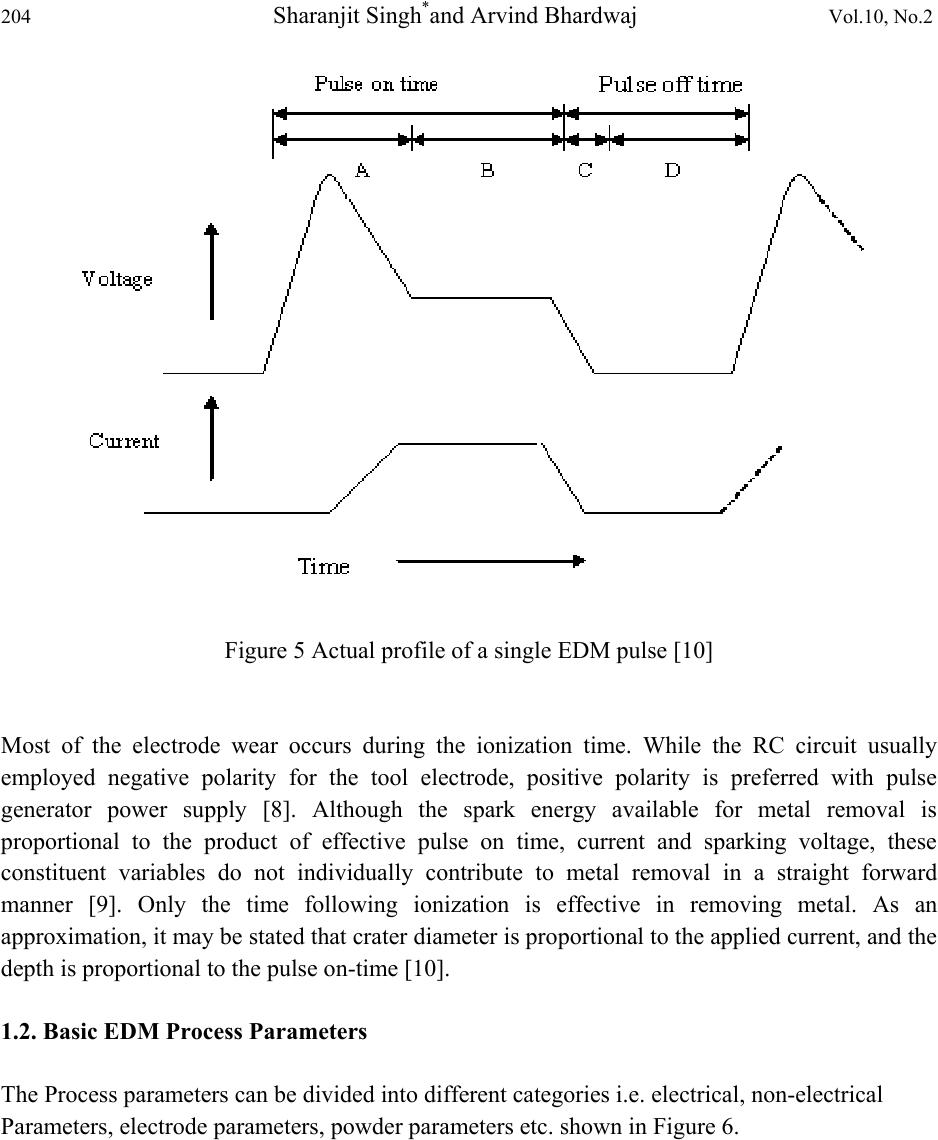 204 Sharanjit Singh*and Arvind Bhardwaj Vol.10, No.2 Figure 5 Actual profile of a single EDM pulse [10] Most of the electrode wear occurs during the ionization time. While the RC circuit usually employed negative polarity for the tool electrode, positive polarity is preferred with pulse generator power supply [8]. Although the spark energy available for metal removal is proportional to the product of effective pulse on time, current and sparking voltage, these constituent variables do not individually contribute to metal removal in a straight forward manner [9]. Only the time following ionization is effective in removing metal. As an approximation, it may be stated that crater diameter is proportional to the applied current, and the depth is proportional to the pulse on-time [10]. 1.2. Basic EDM Process Parameters The Process parameters can be divided into different categories i.e. electrical, non-electrical Parameters, electrode parameters, powder parameters etc. shown in Figure 6.  Vol.10, No.2 Review to EDM by Using Water and Powder-Mixed Dielectric Fluid 205 205 Figure 6 Process parameters and performance measures of EDM Process a cause and effect diagram 1.2.1. Electrical parameters 1.2.1.1. Peak current The peak current is basically a most important machining parameter in EDM. It is the amount of power used in EDM and measures in unit of amperage. During each pulse on-time, the current increases until it reaches a preset level, which is expressed as the peak current. In both die- sinking and wire-EDM processes, the maximum amount of amperage is governed by the surface area of the cut. Higher amperage is used in roughing operations and in cavities or details with large surface areas. Higher currents will improve MRR, but at the cost of surface roughness and tool wear rate. All these factors are more important in EDM because the machined cavity is a mirror image of tool electrode and excessive wear will obstruct the accuracy of machining. New improved electrode materials, especially graphite, can work on high currents without much damage [1]. 1.2.1.2 Discharge voltage Before current can flow, the open gap voltage increases until it has created an ionization path through the dielectric. Once the current starts to flow, voltage drops and stabilizes at the working Pulse on time Electrical parameters Electrode parameters Non-Electrical parameters Powder parameters Supply voltage Pulse off time Flushing Lift time Working time Tool, workpiece rotation Polarit y Electrode gap Powder type Powder concentration Abrasive size Material type Size EDM process measures (MRR, TWR & SR)  206 Sharanjit Singh*and Arvind Bhardwaj Vol.10, No.2 gap level. The preset voltage determines the width of the spark gap between the leading edge of the electrode and workpiece. Higher voltage settings increase the gap, which improves the flushing conditions and helps to stabilize the cut. MRR, tool wear rate (TWR) and surface roughness increases, by increasing open circuit voltage, because electric field strength increases. However, the impact of changing open circuit voltage on surface hardness after machining has been found to be only marginal. Discharge voltage in EDM is related to the spark gap and breakdown strength of the dielectric [11]. 1.2.1.3. Pulse on time and pulse off time These are expressed in units of microseconds. Because all the cutting is done during pulse on- time, so the duration of these pulses and the number of cycles per second (frequency) have vital role. Metal removal is directly proportional to the amount of energy applied during the pulse on- time [12]. This energy is controlled by the peak current and the length of the pulse on-time. Pulse on-time is commonly referred to as pulse duration and pulse off-time is called pulse interval. With longer pulse duration, more workpiece material will be melted away. The resulting crater will be broader and deeper than a crater produced by shorter pulse duration. This will increase the surface roughness. Extended pulse duration also allow more heat to sink into the workpiece and spread, which means the recast layer will be larger and deeper heat affected zone. However, extreme pulse duration can be counter-productive. When the optimum pulse duration for each tool and workpiece material combination is exceeded, material removal rate starts to decrease. Long pulse duration can also restrict electrode from machining. At this situation, increasing the duration further causes the electrode to grow from plating build-up. The cycle is completed when sufficient pulse interval is allowed before the start of the next cycle. Pulse interval will affect the speed and stability of the cut. According to theory, the shorter the interval, the faster will be the machining operation. But if the interval is too short, the expelled workpiece material will not be flushes away with the flow of the dielectric fluid and the dielectric fluid will not be deionized. This will cause the next spark to be unstable and slows down cutting more than long, stable off- times. At the same time, pulse interval must be greater than the deionization time to prevent continued sparking at one point [10]. Modern power supplies allow independent setting of pulse on-times and pulse off-times. Typical ranges are from 2 to 1000µs. In ideal conditions, each pulse creates a spark. However, it has been observed practically that many pulses fail if duration and interval are not properly set, causing a loss of the machining efficiency. 1.2.1.4. Polarity The polarity of the electrode can be either positive or negative. But the excess material is removed from side which is positive. When series discharge starts under the electrode area and passes through the gap, which creates high temperature causing material evaporation at the faces of both the electrode. The plasma channel is composed of ion and electron flows. As the electron  Vol.10, No.2 Review to EDM by Using Water and Powder-Mixed Dielectric Fluid 207 207 processes (mass smaller than anions) show quicker reaction, the anode material is worn out predominantly. This effect causes minimum wear to the tool electrodes and becomes of importance under finishing operations with shorter pulse on-times. However, while running longer discharges, the early electron process predominance changes to positron process (proportion of ion flow increases with pulse duration), resulting in high tool wear. In general, polarity is determined by experiments and is a matter of tool material, work material, current density and pulse length combinations. Modern power supplies insert an opposite polarity “swing pulse” at fixed intervals to prevent arcing. A typical ratio is 1 swing pulse for every 15 standard pulses [1]. 1.2.1.5. Electrode gap The tool servo-mechanism is employed in EDM machine; its function is to control responsively the working gap to the set value. Mostly electro-mechanical (DC or stepper motors) and electro- hydraulic systems are used, and are normally designed to respond to average gap voltage Figure 7. Basic requirements for good performance are gap stability and the reaction speed of the system; the presence of backlash is particularly undesirable. The reaction speed must be high in order to respond to short circuits or open gap conditions. Gap width is not measurable directly, but can be inferred from the average gap voltage [9, 13]. Figure 7 Electrode feed control in EDM [15] 1.2.2. Non- Electrical parameters 1.2.2.1. Dielectric flushing  208 Sharanjit Singh*and Arvind Bhardwaj Vol.10, No.2 The dielectric fluid used in EDM have characteristics of high dielectric strength and quick recovery after breakdown, effective quenching and flushing ability, good degree of fluidity and easily available. TWR and MRR are affected by the type of dielectric and the method of its flushing [14]. The different types of flushing are injection flushing, suction flushing, side flushing and flushing by dielectric pumping [15]. Lonardo and Bruzzone exposed that flushing during the roughing operation affected the MRR and TWR, while in the finishing operation; it influenced the SR [16]. The flushing rate also influences the crack density and recast layer, which can be minimized by obtaining an optimal flushing rate [14]. In flushing most dielectric fluids are hydrocarbon compounds or water. Deionized water is used for wire-EDM and high precision die-sinking because of its low viscosity and carbon-free characteristics. The dielectric fluid is flushed through the spark gap to remove gaseous and solid debris during machining and to maintain the dielectric temperature by acting as coolant also. A control feature that is available on many machines to facilitate chip removal is vibration or cyclic reciprocation of the servo- controlled tool electrode to create a hydraulic pumping action. Levy and Ferroni, also investigate that Orbiting of the tool or workpiece has also been found to assist flushing and improve machining conditions [17]. 1.2.2.2. Rotating the workpiece In addition to the flushing of the dielectric, the techniques of applying rotational motion to the sparking process also affect the EDM performance. Guu and Hocheng [18] provided a workpiece rotary motion to improve the circulation of the dielectric fluid in the spark gap and temperature distribution of the workpiece yielding improved MRR and SR. On the other hand, Kunieda and Masuzawa [19] proposed a horizontal EDM (HEDM) process in which the main machining axis is horizontal instead of the conventional vertical axis. The change in the basic construction in addition to the rotary motion of the workpiece offered an accessible evacuation of debris improving the erosion efficiency and accuracy of the sparking process. HEDM has also been experimented in the micro-machining of small parts [20, 21]. 1.2.2.3. Rotating the electrode Similarly, the performance measures of the EDM process also improves by the introduction of the rotary motion to the electrode. It serves as an effective gap flushing technique, which significantly improves the MRR and SR [22, 23, 24]. The same alloying effect of migrating material elements from the workpiece and tool is also observed, in relation to the morphology, chemical composition and size distribution of debris, when using rotating electrodes [25]. It was found that the vibratory motion yields comparable effects as the rotary motion of electrode improving the MRR, enhancing the surface quality of workpiece and increasing the stability of machining process. 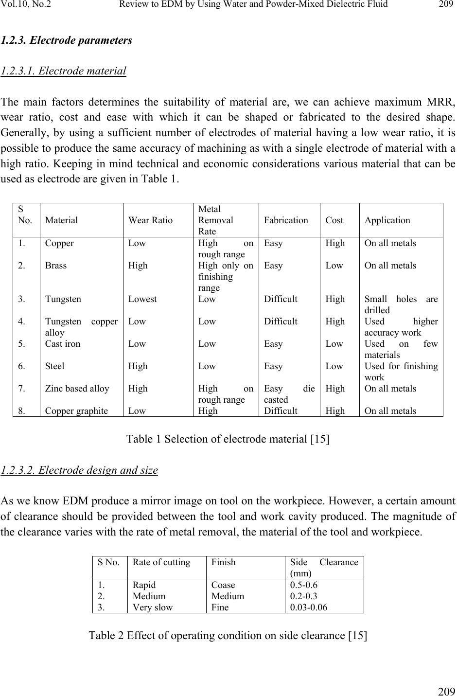 Vol.10, No.2 Review to EDM by Using Water and Powder-Mixed Dielectric Fluid 209 209 1.2.3. Electrode parameters 1.2.3.1. Electrode material The main factors determines the suitability of material are, we can achieve maximum MRR, wear ratio, cost and ease with which it can be shaped or fabricated to the desired shape. Generally, by using a sufficient number of electrodes of material having a low wear ratio, it is possible to produce the same accuracy of machining as with a single electrode of material with a high ratio. Keeping in mind technical and economic considerations various material that can be used as electrode are given in Table 1. S No. Material Wear Ratio Metal Removal Rate Fabrication Cost Application 1. 2. 3. 4. 5. 6. 7. 8. Copper Brass Tungsten Tungsten copper alloy Cast iron Steel Zinc based alloy Copper graphite Low High Lowest Low Low High High Low High on rough range High only on finishing range Low Low Low Low High on rough range High Easy Easy Difficult Difficult Easy Easy Easy die casted Difficult High Low High High Low Low High High On all metals On all metals Small holes are drilled Used higher accuracy work Used on few materials Used for finishing work On all metals On all metals Table 1 Selection of electrode material [15] 1.2.3.2. Electrode design and size As we know EDM produce a mirror image on tool on the workpiece. However, a certain amount of clearance should be provided between the tool and work cavity produced. The magnitude of the clearance varies with the rate of metal removal, the material of the tool and workpiece. S No. Rate of cutting Finish Side Clearance (mm) 1. 2. 3. Rapid Medium Very slow Coase Medium Fine 0.5-0.6 0.2-0.3 0.03-0.06 Table 2 Effect of operating condition on side clearance [15]  210 Sharanjit Singh*and Arvind Bhardwaj Vol.10, No.2 Different tools may be needed for rough and fine machining. The effect of operating on side clearance shows in Table 2. We use different computer-aided systems that have been experimentally implemented in the design of the electrode. The major research interest in the production of electrodes using the rapid prototyping technique is also used. 1.2.4. Powder parameters We can take different types of parameters such as concentration of powder, types of powder and abrasive size etc. In powder mixed electric discharge machining (PMEDM) to avoid the wastage of kerosene oil, a small dielectric circulating system is designed. A stirring system is incorporated to avoid the particle settling. The modified circulation and stirring system is designed in such a way that, it can be employed at the commercial level. In this system, a micro pump is installed for better circulation of the powder mixed dielectric fluid. The pump and the stirrer are employed in the same tank in which machining is performed. For constant reuse of powder mixed dielectric fluid, magnetic forces are used to separate the powder particles from the debris produced due to machining. PMEDM has a different machining mechanism from the conventional EDM. In this process, a suitable material in the powder form is mixed into the dielectric fluid of EDM. 2. FUNDAMENTAL EDM SETTINGS The polarity, pulse duration, pulse interval and peak current are the basic machine settings. These parameters can also be expressed as average current, pulse frequency and duty factor. 2.1. Average Current It is the maximum current available for each pulse from the power supply/generator in the circuit. Average current is the average of the amperage in the spark gap measured over a complete cycle. It is calculated by multiplying peak current by duty factor. Average Current (A) = Duty Factor (%) × Peak Current 2.2. Pulse Frequency It is the number of cycles produced across the gap in one second. The higher the frequency, finer is the surface finish that can be obtained. With an increase of number of cycles per second, the length of the pulse on-time decreases. Short pulse on-times remove very little material and create smaller craters. This produces a smoother surface finish with less thermal damage to the workpiece. Pulse frequency is calculated by dividing 1000 by the total cycle time (pulse on-time + pulse off-time) in microseconds. Pulse Frequency (kHz) = 1000/Total cycle time (µs)  Vol.10, No.2 Review to EDM by Using Water and Powder-Mixed Dielectric Fluid 211 211 2.3. Duty Factor Duty factor is a percentage of the pulse duration relative to the total cycle time. Generally, a higher duty factor means increased cutting efficiency. It is calculated in percentage by dividing pulse duration by the total cycle time (pulse on-time + pulse off-time). Duty Factor (%) = [Pulse duration (µs)/Total cycle time (µs)] × 100 3 PERFORMANCE MEASURES Large numbers of papers have been focused on ways of yielding optimal EDM performance. Performance measures in EDM are MRR, TWR and SR. In MRR research work focused on metal removal mechanism and methods of improving MRR [26, 27, 28]. Similarly research work on tool wear process and methods of improvement in process has been reported [29, 30, 31]. Though EDM is essentially a material removal process, efforts have been made to use it as a surface treatment method and/or an additive process. Many surface changes have been reported ever since the process established itself in the tool rooms of manufacturing industry [32]. 4. TYPES OF EDM 4.1. Sinking EDM In this sinking EDM process, on the surface of workpiece a mirror image of tool shape occurs. In sinking EDM electrode material is generally copper or graphite. The numerical control monitors the gap conditions (voltage and current) and synchronously controls the different axes and the pulse generator. The dielectric liquid is filtrated to remove debris particles and decomposition products. In this process electrical energy turns into thermal energy through a series of discrete electrical discharges occurring between the electrode and workpiece immersed in a dielectric fluid [33]. The thermal energy generates a channel of plasma between the cathode and anode. When the pulsating direct current supply is turned off, the plasma channel breaks down. This causes a sudden reduction in the temperature allowing the circulating dielectric fluid to implore the plasma channel and flush the molten material from the workpiece surface. 4.2. Wire EDM Wire-cut EDM (WEDM) is one of the most favorable variants owing to its ability to machine conductive, exotic and high strength and temperature resistive (HSTR) materials with the scope of generating intricate shapes and profiles [34]. It uses a thin continuously traveling wire feeding through the workpiece by a micro-processor eliminating the need for elaborate reshaped electrodes, which are required in the EDM. The Wire-Cut EDM process uses a thin copper wire of diameter about 0.1 to 0.3 mm as the electrode and the workpiece is mounted on a CNC-  212 Sharanjit Singh*and Arvind Bhardwaj Vol.10, No.2 controlled worktable, enabling complex two dimensional shapes can be cut on the work piece by controlled the movement of the X-Y worktable [35]. Wire EDM process is widely applied not only in tool and die-making industry, but also in the fields of medicine, electronics and the automotive industry [36]. 4.3. Micro EDM The recent trend in reducing the size of products has given micro-EDM a significant amount of research attention. Micro-EDM is capable of machining not only micro-holes and micro-shafts as small as 5µm in diameter but also complex three-dimensional (3D) micro cavities [37].Micro EDM process is basically of four types - micro-wire EDM, die-sinking micro-EDM, micro EDM drilling and micro-EDM milling. In micro-wire EDM, a wire which has a diameter down to 0.02 mm is used to cut through a workpiece. In die-sinking micro-EDM, an electrode is used containing micro-features to cut its mirror image in the workpiece. In micro EDM drilling, micro-electrodes (of diameters down to 5–10 µm) are used to ‘drill’ micro-holes in the workpiece. In Micro-EDM milling, micro-electrodes (of diameters down to 5–10 µm) are employed to produce 3D cavities by adopting a movement strategy similar to that in conventional milling. 4.4. Powder Mixed EDM The mechanism of PMEDM is totally different from the conventional EDM [38]. A suitable material in the powder form is mixed into the dielectric fluid of EDM. When a suitable voltage is applied, the spark gap filled up with additive particles and the gap distance setup between tool and the workpiece increased from 25–50 to 50–150 mm [39]. The powder particles get energized and behave in a zigzag fashion Figure 8. These charged particles are accelerated by the electric field and act as conductors. The powder particles arrange themselves under the sparking area and gather in clusters. The chain formation helps in bridging the gap between both the electrodes, which causes the early explosion. Faster sparking within discharge takes place causes faster erosion from the work piece surface. Figure 8 Principle of powder mixed EDM [55]  Vol.10, No.2 Review to EDM by Using Water and Powder-Mixed Dielectric Fluid 213 213 4.5. Dry EDM In this process a thin walled pipe is used as tool electrode through which high-pressure gas or air is supplied. The role of the gas is to remove the debris from the gap and cooling of the inter electrode gap. The technique was developed to decrease the pollution caused by the use of liquid dielectric which leads to production of vapors during machining and the cost to manage the waste. 5. RESEARCH WORK USING EDM EDM is basically a material removal process. The researches have classified the numerous EDM research interests referred in the papers into four different major areas as shown in Figure 9. Enormous work has been reported ever since the process established itself. However, in this section discussion is only about water and powder mixed dielectric as dielectric fluid. Figure 9 Classification of major EDM research areas [1] 5.1 EDM with Water as Dielectric Fluid In 1981 jaswani investigated the performances of kerosene and distilled water over the pulse energy range 72–288 mJ [40]. Machining in distilled water resulted in a higher MRR and a lower tool wear rate than in kerosene when a high pulse energy range was used. He also noticed that with distilled water, the machining accuracy was poor but the surface finish was better. Tariq Jilani and Pandey in the year 1984 measures the performance of water as dielectric fluid in EDM EDM Research Area Optimizing process variables Improving the performance measures Fuzzy logic Electrical & non-electrical parameters EDM developments Monitoring & Control the Process MRR TWR Hybrid machining process Pulse/time domain Electrode design & manufacture EDM application SR Radio Frequency  214 Sharanjit Singh*and Arvind Bhardwaj Vol.10, No.2 using distilled water, tap water and a mixture of 25% tap and 75% distilled water [41]. The best machining rates have been achieved with the tap water and machining in water has the possibility of achieving zero TWR when using copper tools with negative polarities. Koenig and Joerres in 1987 perform by taking aqueous glycerine solution as additive in water [42]. He reported that a highly concentrated aqueous glycerine solution has an advantage as compared to hydrocarbon dielectrics when working with long pulse durations and high pulse duty factors and discharge currents, i.e. in the roughing range with high open-circuit voltages and positive polarity of tool electrode. Konig and Siebers in 1993 explained the influence of the working medium on the metal removal process [43]. They indicated that working medium has a sustained influence on the metal removal process. The erosion process in which water is used as dielectric consequently possesses higher thermal stability and much higher power input can be achieved especially under critical conditions, allowing much greater increases in the MRR. A considerable difference between conventional oil based dielectrics and aqueous media is specific boiling energy of aqueous media is some eight times higher and boiling phenomena occur at a lower temperature level. Another study on surface modification of aluminium was done by Tsunekawa in 1994 using powder compact electrodes having 64% Ti and 36% Al and they obtained fine dendritic precipitates of titanium carbide on the machined surface [44]. The electrode was connected to negative polarity and kerosene was used as the working fluid. The average diameter and alloyed depth of discharge craters increased with increase in pulse width, the other important factor being the discharge current. It was found that the forming pressure of the powder metallurgy electrodes did not affect material transfer. Kruth in1995 also succeeded in depositing aluminium on steel and TiC on aluminium using Al and Ti–Al green compact electrodes respectively with a traditional EDM machine [45]. This was obtained by using porous electrodes with negative polarity favoring high tool wear. During investigating on white surface layer, the use of an oil dielectric increases the carbon content in the white layer and appears as iron carbides (Fe3C) in columnar, dendritic structures while machining in water causes a decarbonization. While investigating the influence of kerosene and distilled water as dielectric on Ti–6A1–4V work pieces. Chen found that carbide is formed on the work piece surface while using kerosene while oxide is formed on the work piece surface while using distilled water [46]. The debris size of Ti–6Al–4V alloy in distilled water is greater than that in kerosene and compared with kerosene, the impulsive force of discharge in distilled water is smaller but more stable. In year 2004 Leao and Pashby investigated that some researchers have studied the feasibility of adding organic compound such as ethylene glycol, polyethylene glycol 200, polyethylene glycol 400, polyethylene glycol 600, dextrose and sucrose to improve the performance of demonized water [47]. The surface of titanium has been modified after EDM using dielectric of urea solution in water [48]. The nitrogen element decomposed from the dielectric that contained urea,  Vol.10, No.2 Review to EDM by Using Water and Powder-Mixed Dielectric Fluid 215 215 migrated to the work piece forming a TiN hard layer which resulting in good wear resistance of the machined surface after EDM. Ekmekci presented an experimental work to measure residual stresses and hardness depth in EDM surfaces [49]. Stresses are found to be increasing rapidly with respect to depth, attaining to its maximum value around the yield strength and then fall rapidly to compressive residual stresses in the core of the material since the stresses within plastically deformed layers are equilibrated with elastic stresses. In 2005, Sharma investigated the potential of electrically conductive chemical vapor deposited diamond as an electrode for micro-electrical discharge machining in oil and water [50]. While doing a comparative study on the surface integrity of plastic mold steel in the same year Ekmekci also investigated found that the amount of retained austenite phase and the intensity of micro cracks have found to be much less in the white layer of the samples machined in de-ionized water [51]. A new application in EDM power supply was designed to develop small size EDM systems by Casanueva [52]. The proposed control achieves an optimum and stable operation using tap water as dielectric fluid to prevent the generation of undesired impulses and keep the distance between the electrode and the work piece within the desirable range. In the same year Kang and Kim studied in order to investigate the effects of EDM process conditions on the crack susceptibility of a nickel-based super alloy revealed that depending on the dielectric fluid and the post-EDM process such as solution heat treatment, cracks exist in recast layer could propagate into substrate when a 20% strain tensile force was applied at room temperature [53]. When kerosene as dielectric, it was observed that carburization and sharp crack propagation along the grain boundary occurred after the heat treatment. However, using deionized water as dielectric the specimen after heat treatment underwent oxidation and showed no crack propagation behavior. Figure 10 The micro-slit outlook profile SEM photos of using pure water alone and added SiC powder [54]  216 Sharanjit Singh*and Arvind Bhardwaj Vol.10, No.2 In year 2008 Han-Ming Chow and other scientist investigated the effect of using pure water and a SiC powder for titanium (Ti) alloy in micro-slit EDM, and found that by using pure water as an EDM dielectric fluid for titanium alloy yields a high MRR and relatively low electrode wear and small expanding-slit by employing negative polarity (NP) processes [54]. Pure water and a SiC powder cause high conductivity; therefore, the gap was larger than using pure water in the EDM processes. Pure water and a SiC powder could disperse the discharging energy that refines the surface roughness effectively and also attains a higher MRR simultaneously than that of pure water. Pure water and a SiC powder causes a larger expanding-slit and electrode wear than those of using pure water alone. However, pure water and a SiC powder attain a smaller amount of machined burr than that of using pure water alone. The SEM photo using pure water in Figure 10 shows burrs formed on the slit edge. This is because there is a smaller discharge impact, which cannot remove molten material completely during the EDM processes. However, using pure water and SiC powder disperses energy and improves the surface roughness so fewer micro-slit burrs were created. 5.2 EDM with Powder-Mixed in Dielectric Fluid (PMEDM) In the powder mixed EDM powder of different materials mixed in dielectric fluid. The floating particles impede the ignition process by creating a higher discharge probability and lowering the breakdown strength of the insulating dielectric fluid. As a result, MRR, SR is increased, TWR is lowered and sparking efficiency is improved. Because conductive powders enlarge the gap distance and dispersing the discharges more randomly throughout the surface [12].Thickness of the recast layer is smaller and micro-cracks are reduced. Consequently, the corrosion resistance of the machined surface is substantially improved. It can also be concluded by H.K. Kansal in 2007 that PMEDM holds a bright promise in application of EDM, particularly with regard to process productivity and surface quality of workpiece [55]. During review of literature it is observed that most of the research works using powder mixed dielectric focus on improving the process parameters such as material removal rate MRR, TWR and surface roughness. Early years the study of the impact of such machining on surface modification began. For achieving surface modification by powder-mixed dielectric, an inverse or reverse polarity arrangement (negative tool electrode) is universally recommended. Some of the powders that have already been used are Ni, Co, Fe, Al, Cr, Cu, Ti, C (graphite), Si, SiC and Mo with quoted grain sizes between 1µm and 100µm.When abrasive powders such as SiC and alumina were mixed in the dielectric to improve the material removal rate. Such a process has been named PMEDM (powder-mixed EDM) in which machining efficiency can be significantly increased by selecting proper discharge parameters [38]. Jeswani (1981) conducted experiments with addition of 4 g/l of fine graphite powder in the dielectric and found that MRR improved by 60% and electrode wear ratio reduced by about 15% [56].  Vol.10, No.2 Review to EDM by Using Water and Powder-Mixed Dielectric Fluid 217 217 In year 1983 Koshy established that the addition of doping elements to the dielectric medium could be used to impart desired properties to the top layer of the workpiece [57]. Carbon in the hydrocarbon dissociated and combined with the doping elements to form their respective carbides. The workpiece was positive and the tool electrode was negative for such applications. For the same powder concentration, the two main parameters that influenced the doping characteristics were pulse current and pulse duration. Early in year1995 Miyazaki applied a plasma arc produced through a small diameter nozzle on steel [58]. Ceramic powder of silicon carbide was supplied to the processing region with the shielding gas of argon. The initial and running cost of plasma arc is much cheaper than laser beam and it is generally used in industries for cutting and welding applications. It was possible to obtain a hardness of 1000 VHN on AISI 1010 steel by self-quenching without any powder and 1200HV with silicon carbide particles. Figures 11,12 and13 show SEM micrographs of OHNS die steel after machining with tungsten powder, graphite powder, and silicon powder mixed in the dielectric respectively. Remarkable surface modifications can be observed. After this in order to address the problem of powder settling, when we added a surfactant along with aluminium powder in the dielectric and observed a more apparent discharge distribution effect which resulted in a surface roughness Ra value of less than 0.2µm. It has been possible to achieve near mirror-finish using conductive powders (such as graphite and aluminium) and semi conductive silicon powders. Wong in1998 has been shown that besides the appropriate settings of electrode polarity and pulse parameters, there is a great influence of work material and powder properties on the response parameters such as MRR, TWR and surface roughness. Whilst graphite and silicon powders gave mirror-finish on SKH-54 work material, aluminium powder failed to give the same Figure 14 [59]. The use of negative electrode polarity was found to be essential for achieving mirror-finish condition. Okada in year 2000 purposed that the hardness of the modified surface became higher with increase in pulse duration and powder concentration [60]. A distinct influence of the addition of aromatic hydrocarbons to the dielectric fluid on the ignition and breakdown phase of single discharges has also been reported by [61]. Fig.11. SEM micrographs of OHNS die steel after machining with tungsten powder (at Ip =6A, Pon =5µs and Poff =85µs, electrode—copper [58].  218 Sharanjit Singh*and Arvind Bhardwaj Vol.10, No.2 Fig.12. SEM micrographs of OHNS die steel after machining with graphite powder (at Ip =2A, Pon =5µs and Poff =57µs, electrode—copper) [58]. Fig.13. SEM micrograph of OHNS die steel after machining with silicon powder mixed dielectric (at Ip =2A, Pon =5µs and Poff =57µs, electrode—copper) [58]. Fig.14. SEM micrographs of SKH-54 tool steel after machining with copper electrode (a) Without any powder, (b) with graphite powder, (c) with silicon powder and (d) with aluminium powder (at Ip =1A, Pon =7.5µs and Poff =11µs, magnification = 50×, polarity- negative [59]. Furutani in 2001 investigated by using titanium powder in kerosene dielectric and obtained titanium carbide layer of hardness 1600HV on carbon steel with a negatively polarized copper electrode, 3A peak current and 2µs pulse duration [39]. Rotating disk electrode kept the powder concentration high in the machining area. Both titanium and titanium carbide were found in the X-ray diffraction analysis Figure 15 of the machined surface and it was concluded that carbon came from the breakdown of the dielectric fluid.  Vol.10, No.2 Review to EDM by Using Water and Powder-Mixed Dielectric Fluid 219 219 Yan in 2005 observed by adding urea to distilled water as the dielectric medium for machining titanium, he obtained TiN on the work surface which exhibited improved friction and wear characteristics [48]. Both MRR and TWR declined with an increase in pulse duration. Micro-hardness values of the order of 250 Hk were achieved. A deposition method for solid lubricant layer of molybdenum disulphide by suspending its powder in the dielectric to produce parts for ultra high vacuum applications (such as space environment) has been proposed by Furutani and Shimizu in 2003 [61]. High open circuit voltage, low discharge current, short pulse duration and medium pulse interval were used to deposit the lubricant layer on carbon steel and stainless steel. The process has some drawbacks, which include the difficulty in ensuring that the powder is held in suspension. This was easier with more viscous dielectrics but at the cost of reduced flushing efficiency [62]. In order to address the problem of powder settling, Wu in year 2005 added a surfactant along with aluminium powder in the dielectric and observed a more apparent discharge distribution effect which resulted in a surface roughness Ra value of less than 0.2µm [63]. Figure15 (a) SEM micrograph and (b) XRD pattern of AISI-1049 carbon steel after machining with Titanium powder-mixed dielectric (at Ip =3A, Pon =2µs and Poff = 1024µs), electrode— copper, polarity—negative [39].  220 Sharanjit Singh*and Arvind Bhardwaj Vol.10, No.2 Other hand, when Tzeng and Chen conducted experiments on SKD-11 steel with aluminium, chromium, copper and silicon carbide powders, they found that aluminium powder gave the best surface finish followed by chromium, whereas copper powder generated the worst surface characteristics [64]. Besides the work material powder combination; particle size, concentration and powder properties such as density, electrical resistivity and thermal conductivity affected the machining performance. Using high speed framing camera (HSFC) technique, Klocke found a larger plasma channel with aluminium powder-mixed dielectric in contrast to the standard dielectric [65]. With a pulse on-time of 100 µs, photos were taken after a delay of 60µs, in order to snapshoot a fully developed plasma channel. It was concluded that in such cases, the discharge energy got distributed on a bigger workpiece surface. Dielectric flow rate also had an important influence on the process polishing capability [66]. In recent years G.S. Prihandana presents a new method that consists of suspending micro-MoS2 powder in dielectric fluid and using ultrasonic vibration during m-EDM processes [67].The results show that the introduction of MoS2 micro-powder in dielectric fluid and using ultrasonic vibration significantly increase the material removal rate and improves surface quality Figure 16 by providing a flat surface free of black carbon spots. Figure 16 Microstructures of Cu–W surfaces with brass as the tool electrode, obtained by m- EDM process using (a) pure dielectric ; (b) MoS2 concentration of2g/l;(c) MoS2 concentration of5g/l [67]. Kun Ling Wu and other researchers explore the influence of surfactant on the characteristics of electrical discharge machining (EDM) process on mold steel (SKD61) [68]. In this study, particle agglomeration is reduced after surfactant molecules cover the surface of debris and carbon dregs in kerosene solution. Debris is evenly dispersed in dielectric to improve the effects of carbon accumulation and dreg discharge, and reduce the unstable concentrated discharge. The EDM parameters, such as peak current, pulse duration, open voltage and gap voltages are studied. The experimental results show that after the addition of Span 20 (30 g/L) to dielectric, the conductivity of dielectric is increased. The machining efficiency is thus increased due to a shorter relay time of electrical discharge. When proper working parameters are chosen, the material removal rate is improved by as high as 40–80%. Although the improvement of surface  Vol.10, No.2 Review to EDM by Using Water and Powder-Mixed Dielectric Fluid 221 221 roughness is not obvious, the surface roughness is not deteriorated since the material removal rate is great shown in Figure 17. 5.3 Miscellaneous As discussed earlier many studies have been conducted with powder-mixed dielectric under normal machining conditions with the aim of improving the conventional output process parameters. Narumiya in1989 reported that the workpiece machined using the powder (Si, SiC or Al) suspended oil had better surface finish and increased corrosion resistance compared to the surface machined without powder [69]. Electrode wear was found to be lower with water dielectrics containing a powder suspension [70]. Figure 17 Machining depth comparison of different dielectric after 30min EDM (P: +, Ip: 3A, τon: 25µs, and Eg: 40 V): (a) kerosene and (b) kerosene + Span 20. [68]. Significant improvement in surface roughness (both Ra and Rz values) and sharp decline in tool electrode wear with kerosene and deionized water as dielectrics observed [71]. Fredriksson and Hogmark performed EDM of tool steel with three dielectrics [72]. The dielectrics investigated were silicone oil, a hydrocarbon based fluid and liquid nitrogen. Machining was done at different dielectric fluid temperatures using both copper and graphite electrodes. It was found that the type of dielectric fluid had a greater influence on the microstructure and surface layers than its temperature. The only beneficial effect of changing the temperature was a reduced hardness in the layer below the recast layer at elevated temperatures. MRR was very low for EDM in liquid nitrogen and a recast layer rich in electrode material was obtained on the workpiece. No significant difference in the thickness of affected layer was found with change in temperature, dielectric medium or the electrode material. They also concluded that electrode material had a great influence on the properties and composition of the surface layers. 6. CONCLUSIONS AND FUTURE TRENDS Because of EDM enormous improvement in machining process has been achieved in recent years. The capability of machining intricate parts and difficult to cut material has made EDM as one of the most popular machining processes. The contribution of EDM to industries such as cutting new hard materials make EDM technology remains indispensable. The review of the  222 Sharanjit Singh*and Arvind Bhardwaj Vol.10, No.2 research trends in EDM in water and EDM with powder additives is presented. In each topic, the development of the methods for the last 25 years is discussed & noticed much work in PMEDM rather than by using water as dielectric fluid as shown in Figure 18. The progress of development in each area is presented using block diagrams Figures19 and 20. EDM in water is introduced for safe and conducive working environment; EDM with powder additives is concerning more on increasing SQ, MRR and tool wear using dielectric oil and EDM modeling is introduced to predict the output parameters which leads towards the development of precise and accurate EDM performance. For each and every method introduced and employed in EDM process, the objectives are the same: to enhance the capability of machining performance, to get better output product, to develop technique to machine new materials and to have better working conditions. 52% 34% 14% Powdermixe d dielc t ric fluid Waterasdielct ric fluid Miscellaneous Figure 18 Research study conducted in EDM with different dielectric fluid Machining by using different dielectric fluid with EDM process is still at the experimental stage. A number of research studies have been carried out; significant improvements in MRR, surface properties have been reported and the feasibility of the process is well established. However, many more issues need to be investigated before the method can be formally accepted by the industry. The effect of discharge current and pulse duration has been taken into consideration in various research works but variation in pulse interval has not been investigated or it has been taken into consideration in conjunction with pulse duration by way of duty factor. Most of the available research works on powder-mixed dielectric have studied the impact of such machining on MRR, surface roughness and TWR etc. with normal polarity. The study of the impact of this method on surface modification has been taken up by very few researchers. Less work has been reported using powders of important alloying elements such as manganese, chromium, molybdenum and vanadium in the dielectric medium. Likewise, some of the important die steel materials such as OHNS die steel, molybdenum high- speed tool steels and water-hardening die steels (W-series) have not been tried as work materials.  Vol.10, No.2 Review to EDM by Using Water and Powder-Mixed Dielectric Fluid 223 223 Figure19 Research progress by using water as dielectric fluid In 1981 machining in distilled water resulted in higher MRR and lower wear ratio was obnsverd by jaswani [40]. In 1984 the best machining rates have been achieved with tap water as the dielectric fluid; zero electrode wear possible [41]. In 1987 use aqueous solution of organic compounds as medium for EDM sinking almost completely excludes any fire hazard, permitting safe operation of plant [42]. In 1993EDM sinking process can be made more cost effective through the use of water based media, significantly improving competitiveness with other process observed. [43]. 1999 The MRR is greater and the relative wear ratio is lower when machining in distilled water rather than in kerosene [46]. 2004 Water based dielectrics may replace oil-based fluids in die sinkin g a pp lications. [47]. In 2005 TiN was synthesized on the machined surface by chemical reaction that involved elements obtained from the work piece and the urea solution in water as dielectric [48]. The amount of retained austenite phase and the intensity of microcracks has been found to be much less in the white layer of the samples machined in deionized wate r dielectric liquid [49 ]. In 1995 Water dielectric cause decarbonisation in the white layer at the surface of a work piece caused by EDM [45]. In 2008 effect of using pure water and a SiC powder for titanium ( Ti ) allo y in micro-slit EDM observed [54]. In1994A machine tool maker has established technologies for water-immersion machining, greatly improved the surface finish so that post process manual polishing is not required [44].  224 Sharanjit Singh*and Arvind Bhardwaj Vol.10, No.2 Wu In 2005 address the problem of powder settling [63] Kansal in same year studied by optimizing the process parameters of PMEDM by using response surface methodology he analyzed that MRR & SR increases, TWR decreases [12]. Yan in 2005 obtained TiN on the work surface which exhibited improved friction and wear characteristics. Both MRR and TWR declined with an increase in pulse duration. [48]. Tzeng and Chen conducted experiments the best surface finish followed by chromium, whereas copper powder generated the worst surface characteristics. [64] Using high speed framing camera (HSFC) technique, Klocke 2004 found a larger plasma channel with aluminium powder- mixed dielectric [65]. A distinct influence of the addition of aromatic hydrocarbons to the dielectric fluid on the ignition and breakdown phase of single discharges has been reported by Rehbein [61] Furutani and Shimizu (2003) proposed a deposition method for solid lubricant layer of molybdenum disulphide by suspending its powder in the dielectric [64]. (Aspinwall et al., 2003) suggested that it is easier with more viscous dielectrics but at the cost of reduced flushing efficiency [62]. The hardness of the modified surface became higher with increase in pulse duration and powder concentration examined by Okada in 2000 [ 60 ] . Furutani in 2001 used titanium powder in kerosene dielectric and obtained titanium carbide layer of hardness 1600HV on carbon steel [39]. Koshy in 1983 established that the addition of doping elements to the dielectric medium could be used to impart desired properties to the to p la y er [ 57 ] . Jeswani in 1981 conducted experiments with addition of 4 g/l of fine graphite powder and found that MRR improved by 60% and electrode wear ratio reduced b y about 15% [ 56 ] . In a related case of surface modification using powders but not involving the EDM process, investigated by Miyazaki 1995 [58]. It has been possible to achieve near mirror-finish using conductive powders (such as graphite and aluminium) and semi conductive silicon powders purposed by Wong 1998 [59].  Vol.10, No.2 Review to EDM by Using Water and Powder-Mixed Dielectric Fluid 225 225 Figure 20 Research progress by using powder mixed dielectric as dielectric fluid REFERENCES [1] Ho, K.H., Newman, S.T., 2003, “State of the art electrical discharge machining.” International Journal of Machine Tools & Manufacture, Vol. 43, pp. 1287–1300. [2] Lazarenko, B.R., 1943, “To invert the effect of wear on electric power contacts”, Dissertation of the All-Union Institute for Electro Technique in Moscow/CCCP, Russian. [3] Jameson, E.C., 2001, “Description and Development of Electrical Discharge Machining”.Society of Manufacturing Engineers. Dearbern, Michigan, USA. [4] Abu Zeid O.A., 1997, “On the effect of electro discharge machining parameters on the fatigue life of AISI D6 tool steel.” Journal of Materials Processing Technology, Vol. 68, No. 1, pp. 27–32. [5] Schumacher, B.M., 2004 “After 60 years of EDM, the discharge process remains still Disputed.” Journal of Materials Processing Technology, Vol. 149, pp. 376–381. [6] Tsai, K.M., Wang, P.J., 2001, “ Predictions on surface finish in electrical discharge machining based upon neural network models.” International Journal of Machine Tools & Manufacture, Vol. 41, No.10, pp. 1385–1403. [7] Kalpajian, S., Schmid, S.R., 2003, “Material removal processes: abrasive, chemical, electrical and high-energy beam in manufacturing Processes for Engineering Materials”, Prentice Hall, New Jersey, pp. 541. [8] McGeough, J.A., 1988, Advanced Methods of Machi ning, 1st ed. Chapman and Hall, USA, ISBN 0-412-31970-5 [9] Crookall, J.R., Heuvelman, C.J., 1971, “Electro-discharge machining—the state of the art.” Annals of the CIRP, Vol. 20, No. 1, pp. 113–120. Dielectric flow rate also had an important influence on the process polishing capability investigated by Pecas and Henri q ues [66] G.S. Prihandana presents a new method that consists of suspending micro-MoS2 powder in dielectric fluid and using ultrasonic vibration during m-EDM processes and finds increase the MRR and surface quality [67] Kun Ling Wu and other researchers explore the influence of surfactant on the characteristics of electrical discharge machining (EDM) process on mold steel (SKD61) [71]  226 Sharanjit Singh*and Arvind Bhardwaj Vol.10, No.2 [10] Fuller, John, E., 1996, Electrical Discharge Machining. ASM Machining Handbook, vol. 16, pp. 557–564. [11] Kansal. H.K., Singh, S., Kumar, P., (2005) Application of Taguchi method for optimization of powder mixed electric discharge machining, International Journal of Manufacturing Technology and Management, No.7, pp. 329–341 [12] Kansal, H.K., Singh, S., Kumar, P., 2005, “Parametric optimization of powder mixed electrical ischarge machining by response surface methodology.” Journal of Materials Processing Technology, Vol. 169, No. 3, pp. 427–436. [13] Bayramoglu, M,. Duffill, A. W., 1995, “Manufacturing linear and circular contours using CNC EDM and frame type tools.” International Journal of Machine Tools and Manufacture, Vol. 35, No. 8, pp. 1125–1136. [14] Wong, Y.S., Lim, L.C., Lee, L.C., 1995, “Effect of flushing on electro-discharge machined surfaces.” Journal of Materials Processing Technology, Vol. 48, pp. 299–305. [15] Pandey, P.C., Shan, H.S., 1999, Modern Machining Process, Tata McGraw- Hill Publishing Company Ltd, Page 84-113 [16] Lonardo, P.M., Bruzzone. A.A., 1999 “Effect of flushing and electrode material on die sinking EDM”, Ann. CIRP, Vol. 48, No. 1, pp. 123– 126. [17] Levy, G.N., Ferroni, B., 1975, “Planetary spark erosion—applications and optimization”. In: Proceedings of the 16th MTDR Conference, pp. 291–297 [18] Guu, Y.H., Hocheng, H., 2001, “Effects of workpiece rotation on machinability during electrical discharge machining.” J. Mater . M an uf. Processes, Vol. 16, No. 1, pp. 91–101. [19] Kunieda, M., Masuzawa, T., 1988, “A fundamental study on a horizontal EDM.” Ann. CIRP , Vol. 37 No.1, pp. 187–190. [20] Masuzawa, T., Okajima, K., Taguchi, T., 2002, “EDM-lathe for micromachining.” Ann. CIRP, Vol. 51, No. 1, pp. 355–358. [21] Mohri, N., Tsukamoto, J., Fujino, M., 1989, “Drilling of deep microholes by EDM.” Ann. CIRP, Vol. 38, No. 1, pp. 195–198. [22] Yan, B.H., Wang, C.C., Liu, W.D., Huang, F.Y., 2000, “Machining characteristics of Al2O3/6061Al composite using rotary EDM with a disklike electrode.” Int. J. Adv. Manuf. Technol., Vol. 16, No. 5, pp. 322–333. [23] Kagaya, K., Oishi, Y., Yada, K., 1986, “Micro-electro discharge machining using water as a working fluid—I: micro-hole drilling.”, Precision Engineering, Vol. 8, No. 3,pp. 157– 162. [24] Sato, T., Mizutani, T., Yonemochi, K., Kawata, K., 1986, “The development of an electro discharge machine for micro-hole boring.”, Precision Engineering, Vol. 8, No. 3, pp.163– 168. [25] Soni, J.S., 1994, “Microanalysis of debris formed during rotary EDM of titanium alloy (Ti 6Al 4V) and die steel (T 215 Cr12),” Wear, Vol. 177, pp. 71–79.  Vol.10, No.2 Review to EDM by Using Water and Powder-Mixed Dielectric Fluid 227 227 [26] Soni, J.S., Chakraverti, G. 1996, “Experimental investigation on migration of material during EDM of T 215 Cr12 die steel.” Journal of Materials Processing Technology, Vol. 56, pp. 439–451. [27] Kaneko, T., Tsuchiya, M. 1984, “Three dimensionally controlled EDM using cylindrical electrode.” J. Japan Soc. Electr. Machining Eng, Vol. 18, No. 35, pp. 1–4. [28] Roethel, F., Garbajs, V., 1976, “Contributions to the micro-analysis of spark eroded surfaces.” Annals of the CIRP, Vol. 25, No. 1, pp.135–140. [28] Marafona, J., Wykes, C., 2000, “A new method of optimizing material removal rate using EDM with copper tungsten electrodes.” International Journal of Machine Tools & Manufacture, Vol. 40, No. 2, pp.153–164. [29] Mohri, N., Suzuki, M., Furuya, M., Saito, N., 1995, “Electrode wear process in electrical discharge Machining.” Ann. CIRP, Vol. 44, No. 1, pp.165–168. [30] Staelens, F., Kruth, J.P., 1989, “A computer integrated machining strategy for planetary EDM.” Ann. CIRP , Vol. 38, No. 1, pp. 187–190. [31] Schumacher, B. M. 1983, “EDM technology for precision workpieces with excellent surface quality.” Proceedings of the ISEM-7, pp. 124–135. [32] Tsai, H. C., Yan, B.H., Huang, F. Y., 2003, “ EDM performance of Cr/Cubased composite Electrodes.” Int. J. Mach. Tools Manuf. Vol. 43, No. 3 , pp. 245–252. [33] Puri, A. B., Bhattacharyya, B., 2003, “An analysis and optimisation of the geometrical inaccuracy due to wire lag phenomenon in WEDM.” Int. J. Mach. Tools Manuf. Vol. 43, No. 2, pp. 151–159. [34] Lok, Y. K., Lee, T.C., 1995, “Wire-Cut Electrical Discharge Machining of SIALON Ceramics.” Proc. Seventh Int. Manuf. Conf. with China. Harbin, China, pp. 71-76 [35] Mu Tian Yan, Yi Peng Lai, 2007, “Surface quality improvement of wire-EDM using a fine finish power supply.” International Journal of Machine Tools & Manufacture, Vol. 47, pp. 1686–1694. [36] Rajurkar, K.P., Yu, Z.Y. 2000, “3D micro-EDM using CAD/CAM.” Ann. CIRP , Vol. 49, No. 1, pp. 127–130. [37] Zhao, W. S., Meng, Q. G., Wang, Z. L. 2002, “The application of research on powder mixed EDM in rough machining.” Journal o f Materials Proces sing Technology, Vol. 129, pp. 30–33 [38] Furutani, K., Saneto, A., Takezawa, H., Mohri, N., Miyake, H., 2001, “Accretion of titanium carbide by electrical discharge machining with powder suspended in working fluid.”Precision Engineering, Vol. 25, pp.138–144 [39] Jeswani, M.L., 1981, “Electrical discharge machining in distilled water.” Wear, Vol. 72, pp. 81–88. [40] Tariq, S. Jilani., Pandey, P.C., 1984, “ Experimetnal investigations into the performance of water as dielectric in EDM.” International Journal of Machine Tool Design and Research, Vol. 24, pp. 31–43.  228 Sharanjit Singh*and Arvind Bhardwaj Vol.10, No.2 [41] Koenig, W., Joerres, L., 1987, “A aqueous solutions of organic compounds as dielectric for EDM sinking.” CIRP Annals—Manufacturing Technology, Vol. 36, pp. 105–109. [42] Konig, W., Siebers, F. J., 1993, “Influence of the working medium on the removal process in EDM sinking, American Society of Mechanical Engineers.” Production Engineering Division (Publication) PED, Vol. 64, pp. 649–658. [43] Tsunekawa, Y., Okumiya, M., Mohri, N., Takahashi, I., 1994, “Surface modification of aluminum by electrical discharge alloying.” Materials Science and Engineering A174, pp. 193–198. [44] Kruth, J.P., Stevens, L., Froyen, L., Lauwers, B. 1995, “Study of the white layer of a surface machined by die-sinking electro-discharge machining.” CIRP Annals— Manufacturing Technology, Vol. 44, pp.169–172. [45] Chen, S.L., Yan, B.H., Huang, F.Y., 1999, “Influence of kerosene and distilled water as dielectric on the electric discharge machining characteristics of Ti-6Al-4V.” Journal of Materials Processing Technology, Vol. 87, pp. 107–111 [46] Leao, F.N., Pashby, I.R. 2004, “A review on the use of environmentally friendly dielectric fluids in electrical discharge machining.”, Journal of Materials Processing Technology, Vol. 149, pp. 341–346. [47] Yan, B.H., Tsa, H.C., Huang, F.Y., 2005, “The effect in EDM of a dielectric of a urea solution in water on modifying the surface of titanium.” International Journal of Machine Tools & Manufacture, Vol. 45, No. 194–200. [48] Ekmekci, B., Elkoca, O., Tekkaya, A.E., Erden, A, 2005, “Residual stress state and hardness depth in electric discharge machining: de-ionized water as dielectric liquid.” Machining Science and Technology, No. 9, pp. 39–61. [49] Sharm, A., Iwai, M., Suzuki, K., Uematsu, T. 2005, “Potential of electrically conductive chemical vapor deposited diamond as an electrode for micro-electrical discharge machining in oil and water.” New Diamond and Frontier Carbon Technology, Vol. 15, pp. 181–194. [50] Ekmekci, B., Elkoca, O., Erden, A., 2005, “A comparative study on the surface integrity of plastic mold steel due to electric discharge machining.” Metallurgical and Materials Transactions B: Process Metallurgy and Materials Processing Science, Vol. 36, pp.117– 124. [51] Casanueva, R., Azcondo, F.J., Bran, C., Bracho, S., 2005, “Analysis design and Experimental results of a high-frequency power supply for spark erosion.” IEEE Transactions on Power Electronics, Vol. 20, pp. 361–369. [52] Kang, S. H., Kim, D.E., 2005, “Effect of electrical discharge machining process on crack susceptibility of nickel based heat resistant alloy.”, Materials Scien ce an d Te chno logy , Vol. 21, pp.817– 823. [53] Chow, H. M., Yang, L. D., Lin, C. T., Chen, Y. F., 2008, “The use of SiC powder in water as dielectric for micro-slit EDM machining.”journal of materials processing technology, Vol. 195, pp. 160–170  Vol.10, No.2 Review to EDM by Using Water and Powder-Mixed Dielectric Fluid 229 229 [54] Kansal, H.K., Singh, S., Kumar P., 2007, “Technology and research developments in powder mixed electric discharge machining (PMEDM).”, Journal of Materials Processing Technology, Vol. 184, pp.32–41. [55] Jeswani, M.L., 1981, “Effect of addition of graphite powder to kerosene used as a dielectric fluid in electrical discharge machining.” Wear, Vol. 70, pp. 133–139. [56] Koshy, G., Philip, P.K., Geddam, A., 1983, “Hardening of surface layers using electric discharge techniques.” In: Proceedings of the 11th AIMTDR Conference, IIT, Madras, pp. 315–319 [57] Miyazaki, T., Yoshioka, S., Kimura, T., Kinoshita, N., 1995, “Surface modification of steel by a small diameter plasma arc.” Annals of CIRP, Vol. 44, No. 1, pp.161–16. [58] Wong , Y.S., Lim, L.C., Rahuman, I., Tee, W.M. 1998, “Near mirror-finish phenomenon in EDM using powder-mixed dielectric.” Journal of Materials Processing Technology, Vol. 79, pp. 30–40. [59] Okada, A., Uno, Y., Hirao, K., 2000, Formation of hard layer by EDM with carbon powder mixed fluid using titanium electrode. In: Proceedings of the International Conference on Progress of Machinin g Tec hn ol og y, pp. 464–469 [60] Rehbein, W., Schulze, H.P., Mecke, K., Wollenberg, G., Storr, M., 2004, “Influence of Selected groups of additives on breakdown in EDM sinking.”, Journal of Materials Processing Technology, Vol. 149, pp. 58–64. [61] Furutani, K., Shimizu, Y., 2003, Experimental analysis of deposition process of lubricant surface by EDM with molybdenum disulphide powder suspended in working oil. Proceedings of the American Society for Precision Engineering, Vol. 30, pp. 547–550. [62] Aspinwall, D.K., Dewes, R.C., Lee, H.G., Simao, J., 2003, “Electrical discharge surface alloying of Ti and Fe workpiece materials using refractory powder compact electrodes and Cu wire.” Annals of the CIRP, Vol. 52, No. 1, pp. 151–160. [63] Wu, K.L., Yan, B.H., Huang, F.Y., Chen, S.C., 2005, “ Improvement of surface finish on SKD steel using electro-discharge machining with aluminum and surfactant added dielectric.” Inte rnational Journal of Machine Tools & Manufacture, Vol. 45, pp.1195–1201 [64] Tzeng, Y., Chen, F. 2005, “Investigation into some surface characteristics of electrical discharge machined SKD-11 using powder-suspension dielectric oil.” Journal of Materials Processing Technology, Vol. 170, pp. 385–391. [65] Klocke, F., Lung, D., Antonoglou, G., Thomaidis, D. 2004, “The effects of powder Suspended dielectrics on the thermal influenced zone by electrodischarge machining with small discharge energies.” Journal of Material Processing Technology, Vol. 149, pp.191– 197 [66] Pecas, P., Henriques, E., 2008, “Effect of the powder concentration and dielectric flow in thesurface morphology in electrical discharge machining with powder mixed dielectric.” International Journal of Advanced Manufacturing Technology, Vol. 37, pp. 1120–1132. [67] Prihandana, G. S., Mahardika, M., Hamdi, M., Wong, Y.S., Mitsui K., 2009, “Effect of micro-powder suspension and ultrasonic vibration of dielectric fluid in micro-EDM  230 Sharanjit Singh*and Arvind Bhardwaj Vol.10, No.2 processes—Taguchi approach.” Inte rn a t io n a l J ou r n al o f Machi ne Tools & Manufacture , Vol. 49, pp. 1035–1041. [68] Wu K. L., Yanb B. H., Lee, J.W., Ding, C.G. 2009, “Study on the characteristics of electrical discharge machining using dielectric with surfactant.” Journal of materials processing technology, Vol. 209, pp. 3783–3789 [69] Narumiya, H., Mohri, N., Saito, N., Ootake, H., Tsunekawa, Y., Takawashi, T., Kobayashi, K. 1989, EDM by powder suspended working fluid. In: Proceedings of the ISEM- 9, Nagoya, Japan, 5–8 [70] Tzeng, Y.F., Lee, C.Y. 2001, “Effect of powder characteristics on electro discharge machining efficiency.” International Journal of Advanced Manufacturing Technology, Vol. 17, No. 8, pp. 586–592. [71] Kozak, J., Rozenek, M., Dabrowski. L., 2003, “Study of electrical discharge machining Usingn powder-suspended working media.” Journal of Engineering Manufacture, Proceedings of the Instrumental Mechanic Engineers, Vol. 217, pp. 1597–1602. [72] Fredriksson, G., Hogmark, S., 1995, “Influence of dielectric temperature in EDM of hot worked tool steel.” Surface Engineering , Vol. 11, No. 4, pp. 324–330. |