Paper Menu >>
Journal Menu >>
 Journal of Minerals & Materials Characterization & Engineering, Vol. 8, No.5, pp 367-378, 2009 jmmce.org Printed in the USA. All rights reserved Characterisation and Pre-concentration of Chromite Values from Plant Tailings Using Floatex Density Separator C. Raghu Kumar1*, Sunil Tripathy1 and D.S. Rao2 1R&D Department, TATA Steel Limited, Jamshedpur, India 2Mineralogy Dept., IMMT, Bhubaneswar, India *Corresponding Author, email: craghu@tatasteel.com, phone: +919204058854 ABSTRACT Classification is a method of separation of fines from coarse particles and also lighter particles from heavier particles. The conventional classifiers, such as, hydrocyclone or mechanical classifiers, decreases the efficiency of the grinding and concentration circuits due to their imperfect separation. In the process of improving the efficiency of classification, a device that has been gaining popularity in recent years is the teeter-bed or hindered-bed separator such as Floatex density separator. Generally for processing chromite ores, different types of gravity methods are employed after crushing, grinding followed by classification. The Tata Steel Chrome Ore Beneficiation (COB) plant is generating 50 tph of tailings assaying 17% Cr2O3. A critical review on practice of the plant operating personnel is concerned in the grade-recovery characteristics of unit operations. But separation insight and influence of different operating and process parameters are essential to understand and control the process. The objective of the present investigation was to study the effect of the important operating variables on floatex density separator and preconcentration of COB plant tailings for the further beneficiation process and found that significant removal of iron bearing mineral such as goethite and silica is possible using FDS in a single stage operation. The maximum of 83% recovery of chromite is possible with 22 to 23% Cr2O3 content and thus obtained FDS underflow is suitable for flotation circuit. A low teeter water flow rate with a high bed pressure removes iron bearing mineral like goethite efficiently in an FDS. Key Words: Hindered settling, Floatex density separator, Classification and Chromite plant tailings.  368 C. Raghu Kumar and Sunil Tripathy Vol.8, No.5 1. INTRODUCTION Classification is a method of separation of fines from coarse particles and also lighter particles from heavier particles. This is performed on the basis of the velocity with which the grains fall through a fluid medium generally water or air [1]. In view of the fact, that the velocity of particles in a fluid medium is dependent not only on the size, but also on the specific gravity and shape of the particles. The conventional classifiers, such as, hydro cyclones or mechanical classifiers, decreases the efficiency of the grinding and concentration circuits due to their imperfect separation. Several attempts have been made to improve the efficiency of classification. They include the use of screens instead of classifiers [2], the use of cone classifiers to process hydro cyclone under flow [3,4] and two stage classification by hydro cyclones [5,6,7]. In the process of improving the efficiency of classification, a device that has been gaining popularity in recent years is the teeter-bed or hindered-bed separator such as Floatex density separator. The upward flow of elutriation water creates a fluidized “teeter-bed” of suspended particles. The small interstices within the bed create high interstitial liquid velocities that resist the penetration of the slow settling particles. As a result, small/light particles accumulate in the upper section of the separator and are eventually carried over the top of the device into a collection launder. Large/heavy particles, which settle at a rate faster than the upward current of rising water, finally pass through the fluidized bed and are discharged out through the bottom of the separator as underflow. The major Indian chromite deposits are located at Sukinda region of Orissa state. The depletion of high grade ore resources and having a variety of gangue minerals such as goethite, serpentine, olivine and talc, etc., has lead to the utilisation of lean ore after beneficiation. Further, ample amount of plant tailing generation have gained importance from the economics, conservation and ecology point of view [8]. Generally for processing chromite ores, different types of gravity methods are employed after crushing, grinding followed by classification. The Tata Steel Chrome Ore Beneficiation (COB) plant, designed to produce concentrate of +46% Cr2O3 with a recovery of 70% from a feed of 30- 35% average Cr2O3. Presently the COB plant produces 50 tph of tailings analysing 17% Cr2O3, which is high [9]. This suggested for the incorporation of additional circuit comprising of hydro cyclone for pre-concentration by de-sliming and multigravity separator and wet high intensity magnetic separator for the upgradation up to the required quality. For recovering chrome values from the Karagedik Concentrate tailings a circuit comprising of wet high intensity magnetic separator and column flotation for producing a concentrate assaying 46 to 48% Cr2O3 was studied by Guney et. al [10].  Vol.8, No.5 Characterisation and Pre-concentration of Chromite 369 A critical review on practice of the plant operating personnel is concerned in the grade-recovery characteristics of unit operations. But separation insight and influence of different operating and process parameters are essential to understand and control the process. The objective of the present investigation was to study the effect of the important operating variables on floatex density separator an d pre-concentration for the further beneficiation process. 2. EXPERIMENTAL The Sukinda COB Plant tailing sample of Tata Steel, India was the feed material in the present studies. The plant tailing as received sample was subjected to characterization in terms of size and chemical assay, size wise microscopic liberation studies. The mineralogical studies were carried out with the help of stereomicroscope and reflected light microscope. The experimental campaign was undertaken in a lab scale Floatex density separator (Model No. LPF-0230), supplied by Outokumpu of 230 mm X 230 mm cross section and 530 mm high (square tank height) followed by a 200mm high conical section. The Floatex density separator (FDS) can be divided into three main zones, • the upper zone (zone A ) above the feed inlet, • the intermediate zone (zone B) between the feed inlet, and teeter water addition point, and • the lower section (z o n e C ) below the teeter water addition point. Feed slurry is introduced to the FDS tangentially through a centralized feed well that extends to approximately one third of the main tank length. Fluidizing (teeter water) is introduced over the entire cross-sectional area at the base of the teeter chamber through evenly spaced water distribution pipes. As the feed enters the main separation zone it expands into a teetered or fluidized bed as a result of the rising current of water. The teeter water flow rate is dependent upon a) feed particle size distribution, b) density and c) the desired cut-point for the separation. The separation takes place in zone B and the separated lighter/finer particles and the coarser/heavier particles leave the separator through zone A and zone C respectively. This separator is equipped with a pressure sensor mounted in zone B above the teeter water pipes and an underflow discharge control valve. The pressure, sensed by a level sensor, is transmitted to the underflow control valve using a specific-gravity set-point controller. The instrumentation helps in maintaining a constant height of the teeter bed and a steady discharge of the underflow. FDS is an efficient hydraulic classifier for classify the material based on their slip velocity. The slip velocity is the relative velocity between the particles and the water velocity and is the function of size and density of the minerals [11]. A schematic diagram of Floatex density separator is presented in Figure 1.  370 C. Raghu Kumar and Sunil Tripathy Vol.8, No.5 About 20 tests were conducted with different combination of operating variables which is shown in table 1. Both the underflow and overflow products for each experiment were collected, dried, weighed and subjected to granulometry and chemical analysis. The experimental data were scrutinized and the performance of the FDS was quantified in terms of cut size (D50), Imperfection (I) and the Cr2O3 percentage recovery of the underflow in each condition. The effect of teeter water flow rate and bed pressure was evaluated. Table: 1 Design of tests with floatex density sep a r a tor Variables Level 1 2 3 4 Teeter water flow rate (in lpm) 6 8 10 12 Bed pressure (in bar) 0.06 0.0650.07 0.075 3. RESULT AND DISCUSSION 3.1. Characterisation Studies As received sample contains 17.76% of Cr2O3 and the major impurities are Fe(T) 22.28%, Al2O3 22.40%, SiO2 5.71%, MgO 3.39%, CaO 0.17% and LOI of 12.55%. The chemical analysis of each size fraction was carried out in an ICP analyser and the analysis data is shown in Table 2. It Overflow Launder Fluidization water Discharge valve Feed B A C Figure 1. Floatex density separator 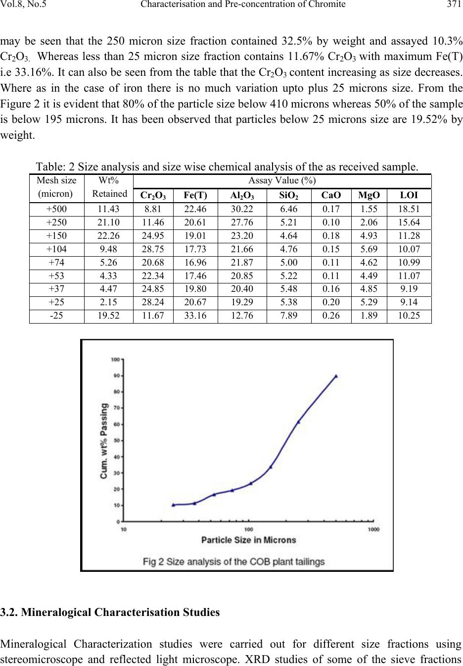 Vol.8, No.5 Characterisation and Pre-concentration of Chromite 371 may be seen that the 250 micron size fraction contained 32.5% by weight and assayed 10.3% Cr2O3. Whereas less than 25 micron size fraction contains 11.67% Cr2O3 with maximum Fe(T) i.e 33.16%. It can also be seen from the table that the Cr2O3 content increasing as size decreases. Where as in the case of iron there is no much variation upto plus 25 microns size. From the Figure 2 it is evident that 80% of the particle size below 410 microns whereas 50% of the sample is below 195 microns. It has been observed that particles below 25 microns size are 19.52% by weight. Table: 2 Size analysis and size wise chemical analysis of the as received sample. Mesh size (micron) Wt% Retained Assay Value (%) Cr2O3 Fe(T) Al2O3 SiO2 CaO MgO LOI +500 11.43 8.81 22.46 30.22 6.46 0.17 1.55 18.51 +250 21.10 11.46 20.61 27.76 5. 21 0.10 2.06 15.64 +150 22.26 24.95 19.01 23.20 4. 64 0.18 4.93 11.28 +104 9.48 28.75 17 .73 21.66 4.76 0.15 5.69 1 0 .07 +74 5.26 20.68 16 .96 21.87 5.00 0.11 4.62 1 0 .99 +53 4.33 22.34 17 .46 20.85 5.22 0.11 4.49 1 1 .07 +37 4.47 24.85 19 .80 20.40 5.48 0.16 4.85 9.19 +25 2.15 28.24 20 .67 19.29 5.38 0.20 5.29 9.14 -25 19.52 11.67 33.16 12.76 7. 89 0.26 1.89 10.25 3.2. Mineralogical Characterisation Studies Mineralogical Characterization studies were carried out for different size fractions using stereomicroscope and reflected light microscope. XRD studies of some of the sieve fractions  372 C. Raghu Kumar and Sunil Tripathy Vol.8, No.5 were also carried out to confirm the mineralogical results. Liberation studies were carried out for the sieve classified samples viz. +500µ; +300µ; +210µ; +150µ; +100µ and -100µ samples.  Vol.8, No.5 Characterisation and Pre-concentration of Chromite 373 3.3. Microscopic Studies Chromite: Chromite occurs as euhedral to subhedral crystal grains, rarely angular and elongated grains are also noticed. Occasionally chromite grains were fractured. Chromite is more enriched in Fe than normal as alternation product from chromite. Rarely the alteration of chromite leads to box-work type texture (Fig.4e). Many times chromite grains are locked either within the iron ore minerals (goethite/hematite) or within silicates or the chromite with inclusions of silicate (Figs.4a and b). Iron minerals: Goethite and hematite are the two main iron ore minerals. Goethite occurs as massive, colloform bands, botryoids and also as highly friable forming fine matrix. Because of this fineness it gives a lateritic coating on the sample (Fig.3 +100µ). Hematite occurs as irregular masses, streaks, laths, and very intimately and intricately associated with goethite. Hematite contains inclusions of chromite and vice versa (Figs.3c and d). Silicate: Generally serpentine and quartz form the silicate matrix in the sample. Quartz is coarse grained and liberated at a coarse size (Fig.3, +300 µ). Many a times it is observed that the serpentine (Fig.3; +500µ) and locked with in the chromite grains (Fig.3; +210 µ and +150µ). 3.4. Effect of Teeter Water on Cut Size (D50) The relation of cut size (D50) with teeter water flow rate and bed pressure is shown in Figure 5. From the figure it is evident that there is an increase in the bed pressure and teeter water flow rate will increase the separation size or cut size from 35 to 125 microns, which has a large impact on the maximum quantity of particles transport to the overflow. This can be explained that when bed pressure increases, the teeter bed height increases, which is a function of teeter water flow rate and bed pressure, there by pushing the coarse particles to overflow launder will increase i.e the distribution of coarse particle is more in overflow. As a result the cut size increases with increase in the bed pressure and teeter water flow rate. 3.5. Effect of Teeter Water on Recovery of Cr2O3 The effect of teeter water flow rate on the percentage recovery of Cr2O3 at different bed pressure is presented in Figure 6. It can be observed from the Figure 6 that with an increase in the teeter water flow rate from 6lpm to 12lpm there is a decrease in the recovery of Cr2O3 in underflow. For example at constant bed pressure (0.06 bar) the recovery to underflow decreases from 93.86% to 86.33%. Similarly at higher bed pressure (0.075 bar) the recovery to underflow is very low i.e 65.92%. This decrease in the recovery of Cr2O3 at underflow is attributed due to the increase in the teeter water flow rate through which the fluidized column will become more  374 C. Raghu Kumar and Sunil Tripathy Vol.8, No.5 loosened and the upward water current may force the fine heavies and coarse lights report into the over flow fraction along with the fine light.  Vol.8, No.5 Characterisation and Pre-concentration of Chromite 375 3.6. Effect of Bed Pressure Floatex density separator works based on the principle of hindered settling. Richardson and Zaki proposed the particle slip velocity, which is the relative velocity between the particle and water velocity, is a function of the terminal settling velocity and liquid fraction of the suspension. When the slip velocity of the particle is equal to the interstitial teeter water velocity, the particle will have a zero velocity with respect to stationary viewer and will have an equal chance to report either to overflow or to the underflow stream. Moreover, the interstitial teeter water velocity is related to the voidage (liquid fraction) of the bed, decreases with increase in bed pressure. The pressure setting determines the accumulation of the deposited material inside the unit and hence the bed height inside the FDS. As the bed height increases the average density and viscosity of the suspension goes up increasing the resistance for the particle to settle. Thus the cut size increase which fa vo r ably reject the gangue minerals. 3.7. Effect of Teeter Bed Pressure on Recovery of Cr2O3 The effect of teeter bed pressure on percentage recovery of Cr2O3 to underflow is shown in Figure 7. It can be illustrated from the figure that there is a decrease in the recovery of Cr2O3 to underflow as teeter bed pressure increases. That shows an increase in the bed height owing to which more loosed fluidized column, the upward water current may force the coarse particles along with the fine chromite particles reporting into the over flow fraction. In other words the coarse lighter and fine heavier particles, having the same slip velocity segregate in the teetered column and push them to overflow fraction. Further this may be elucidated that the bed pressure controls the performance of the classifier. 3.8. Classification Performance Classification is a significant unit operation for separating the mixtures of minerals into two ore more fractions on the basis of the velocity with which the grains fall through a fluid medium. Floatex density separator is a hydraulic classifier which works on the principle of hindered settling and fluidisation. Therefore, the performance is evaluated in terms of imperfection (I) which is defined as I = (D75 – D25) / 2 D50 Where D75 is the particle size where 75% of the mass reported to the underflow, D25 is the particle size where 25% of the mass report to the underflow and D50 is the cut size where 50% of the mass report either to underflow or overflow. The lower imperfection (I) value indicates better classification efficiency which explains the degree of misplacement of the fine particles to the underflow or the short-circuiting of the feed to overflow without any classification.  376 C. Raghu Kumar and Sunil Tripathy Vol.8, No.5 From the Figure 8 it is clear that, as the cut size (D50) increases the separation efficiency or imperfection (I) increases. This can be explained as the cut size increases the coarse light particles will also be pushed to overflow fraction along with the fine heavy particles. A linear dependence of misplacement of particles i.e imperfection (I) on cut size (D50) is evident from the Figure 8. The correlation coefficient was found to be reasonable at 0.83. As the key operating variables i.e. teeter water flow rate and bed pressure which has the direct impact on cut size. So 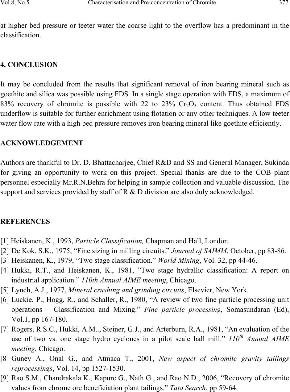 Vol.8, No.5 Characterisation and Pre-concentration of Chromite 377 at higher bed pressure or teeter water the coarse light to the overflow has a predominant in the classification. 4. CONCLUSION It may be concluded from the results that significant removal of iron bearing mineral such as goethite and silica was possible using FDS. In a single stage operation with FDS, a maximum of 83% recovery of chromite is possible with 22 to 23% Cr2O3 content. Thus obtained FDS underflow is suitable for further enrichment using flotation or any other techniques. A low teeter water flow rate with a high bed pressure removes iron bearing mineral like goethite efficiently. ACKNOWLEDGEMENT Authors are thankful to Dr. D. Bhattacharjee, Chief R&D and SS and General Manager, Sukinda for giving an opportunity to work on this project. Special thanks are due to the COB plant personnel especially Mr.R.N.Behra for helping in sample collection and valuable discussion. The support and services provided by staff of R & D division are also duly acknowledged. REFERENCES [1] Heiskanen, K., 1993, Particle Classification, Chapman and Hall, London. [2] De Kok, S.K., 1975, “Fine sizing in milling circuits.” Journal of SAIMM, October, pp 83-86. [3] Heiskanen, K., 1979, “Two stage classification.” World Mining, Vol. 32, pp 44-46. [4] Hukki, R.T., and Heiskanen, K., 1981, ”Two stage hydrallic classification: A report on industrial application.” 110th Annual AIME meeting, Chicago. [5] Lynch, A.J., 1977, Mineral crushing and grinding circuits, Elsevier, New York. [6] Luckie, P., Hogg, R., and Schaller, R., 1980, “A review of two fine particle processing unit operations – Classification and Mixing.” Fine particle processing, Somasundaran (Ed), Vol.1, pp 167-180. [7] Rogers, R.S.C., Hukki, A.M.., Steiner, G.J., and Arterburn, R.A., 1981, “An evaluation of the use of two vs. one stage hydro cyclones in a pilot scale ball mill.” 110th Annual AIME meeting, Chicago. [8] Guney A., Onal G., and Atmaca T., 2001, New aspect of chromite gravity tailings reprocessings, Vol. 14, pp 1527-1530. [9] Rao S.M., Chandrakala K., Kapure G., Nath G., and Rao N.D., 2006, “Recovery of chromite values from chrome ore beneficiation plant tailings.” Tata Search, pp 59-64.  378 C. Raghu Kumar and Sunil Tripathy Vol.8, No.5 [10] Guney A., Sirkesi A. A., Gurkan V., and Onal G., 1996, “The recovery of chromite fines from the tailings of Uckopru chromium plant using HIWMS.” Changing scopes in mineral processing, pp 149-154. [11] Sarkar. B., Das A, and Mehrotra S.P., 2008, “Study of separation features in floatex density separator for cleaning fine coal.” Int. J. Miner. Process., Vol. 86, pp. 40–49. [12] Richardson J. F., and Zaki W. N., 1954, Trans. Inst. Chem. Eng., Vol. 32, pp. 35. |