Journal of Electromagnetic Analysis and Applications
Vol.4 No.7(2012), Article ID:21265,6 pages DOI:10.4236/jemaa.2012.47039
Characteristics of AC-Biased Plasma Antenna and Plasma Antenna Excited by Surface Wave
![]()
1Optics and Electronic Department, Mechanical Engineering College, Shijiazhuang, China; 2China Satellite Maritime Tracking and Control Department, Jiangyin, China.
Email: oec_ljw2009@sohu.com, Bcskk781@gmail.com
Received April 10th, 2012; revised May 11th, 2012; accepted June 10th, 2012
Keywords: Plasma Antenna; AC-Biased; Surface Wave Excited; Characteristics
ABSTRACT
Plasma’s conductive and dielectric properties have been well known for decades. Plasma antenna is a general terms representing using plasma as a conductive medium to transmit or reflect signals. It has unique properties like low RCS (radar cross section), variable impedance and instant on-off capability. Previous plasma antenna uses RF power to generate the plasma column. We developed AC-biased (alternating current) plasma antenna, which has larger operation frequency scale and lower sustaining power. Signals propagated are coupled into the plasma antenna via capacitive coupling. Impedance of the plasma shifts slightly with the AC current. Radiation pattern of the plasma antenna is less uniform than metal antenna and its gain is related to AC power, from the measuring results of AC-biased plasma antenna we found its advantages compare to the plasma antenna excited by the surface wave.
1. Introduction
Plasma antenna is a general term which represents the use of ionized gas as a conducting medium instead of a metal to either transmit or reflect a signal to achieve radar or stealth or other communication purpose [1]. For the purpose of ordinary communication antenna, the transmitted signal relies on surface wave propagation along the plasma column [2,3]. For the purpose of electromagnetic reflection, plasma is used as a conductive reflector if the incoming wave frequency is lower than the plasma frequency. Plasma antenna originates back from the eighties of 20th century, and various ingenious ways has been devised to achieve such purpose. Plasma can be generated by UV laser irradiation, or by laser initiated pre-ionization followed by high voltage breakdown to form the main conducting channel [4], or by simply using commercial fluorescence tube to serve as reflector [5,6], or by much more expensive electron beam [7-9]. There were also exotic methods like explosion generating plasma antenna for fusion research. The more commonly accepted form of plasma antenna was the works of paper [10-13], which was intended as a RF communication antenna. When switched on by a pulsed RF power, the plasma conducts and transmit signal like a metal antenna, when it is off, there is only minor reflection from the glass tube, and hence it has a very low RCS [14]. Previous experiments of Borg et al. have demonstrated plasma antenna excited by the surface wave for HF (3 - 30 MHz) and VHF (30 - 300 MHz) communication with similar efficiency nearly (30% - 70%) and radiation pattern of a metal whip antenna. That antenna was pumped by RF power to generate plasma from the bottom of a glass tube, and the length of plasma column is proportional to the square root of the pump power. In the surface wave excited plasma antenna, in order to create a 100 cm long plasma column, about 200 W of RF power is needed, and the plasma density is a function of length. Such design has the advantage of total zero RCS when the antenna is not energized, but the bandwidth of such antenna is limited to the pumping RF frequency. The cost of pumping RF generator is also very high. The efficiency of existing 100 W - 1 KW class RF amplifiers is usually less than 40%, so over the all system energy efficiency is low, and the dynamic impendence matching of the plasma antenna is very difficult. The related theory and experiment of the plasma antenna excited by the surface wave have been discussed in our paper [15,16].
Here we present a new concept of AC pre-ionized plasma to serve as plasma antenna. The plasma is generated by the high AC voltage, and plasma density of this design is roughly uniform throughout most of the antenna, the power needed to generate the plasma is much lower than previous methods, and power supply setup is much cheaper as well.
Section 2 describes the physical theory of plasma antenna and analysis of plasma antenna; Section 3 explains the experimental setups of AC-biased plasma antenna and the plasma antenna excited by surface wave; Section 4 presents the AC-biased plasma antenna and its comparison with the plasma antenna excited by the surface wave, the radiation pattern and gain of plasma antenna are presented, and finally the conclusions.
2. Theory and Analysis
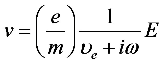
Plasma is a collection of ionized positive ions and free moving electrons; usually the ionization degree is very low, less than 1%. Plasma can be generated by electron impact ionization, photo-ionization, or simply heating the gas, of which the first method is the most energy efficient one. Once plasma is formed, a sheath is formed automatically between the electrode and plasma to maintain the energy and particle balance. Region outside the sheath is called the positive column, where uniform plasma exists, whose density and dimension are determined by the balance between ion diffusion to the surrounding wall of the tube and the ion generation mechanism. Plasma is a dispersive medium; the AC-biased plasma proposed in the paper belongs to nonmagnetic plasma. The relationship between the electron and the electric field of the AC-biased are as follows.
 (1)
(1)
 (2)
(2)
 (3)
(3)
where the  represents the electric force,
  represents the collision frequency of the electron in the plasma. The inner current of plasma antenna can be expressed as (4).
 (4)
(4)
The power of discharge in the plasma can be written as (5), and the permittivity of the plasma can be expressed as (6).
 (5)
(5)
 (6)
(6)
 (7)
(7)
 (8)
(8)
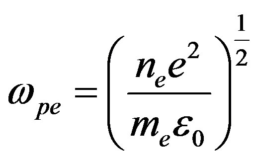
where  is plasma frequency,
  is electron density in
 , and
, and  is the electron-neutral collision frequency. The plasma in the experiment is a low-temperature and non-equilibrium plasma, i.e., the temperature of electron is higher than that of ion.
Basically, plasma is a high pass filter, the signals coupled to the plasma column travels along its axial direction via surface waves, which means the signal causes fluctuations of density along the surface of plasma column, and it decays as it travels.
The plasma antennas excited by surface waves and AC power were employed in the investigation, using the arrangement shown in Figures 1 and 2. The antenna is consisted of a conventional quartz glass tube and filled with argon at a nominal pressure of 133 pa. The transmitted signal launcher consisted of a copper collar of length 25 mm mounted 3 mm below a circular hole cut in the top of a grounded box as shown in Figure 1, the RF signal powered up to 120 W and the frequency at 80 MHz was applied via a directional power meter as shown in Figure 3. The intense electric field developed in the gap between the collar and the box was sufficient to break down the gas. The electric field then drove the resulting surface wave along the interface between the plasma and the glass tube, igniting the plasma along the column. The AC-biased plasma antenna as shown in Figure 1, the power scale of the transformer is from 0 KW to 5 KW, the voltage of the transformer is about 850 V, the AC-biased plasma antenna presents the nearly uniform distribution in the axial direction, and thus it is more stable compare to the plasma antenna excited by the surface wave.
3. Experiment Setup
The plasma antenna is constructed from the 12 mm outer
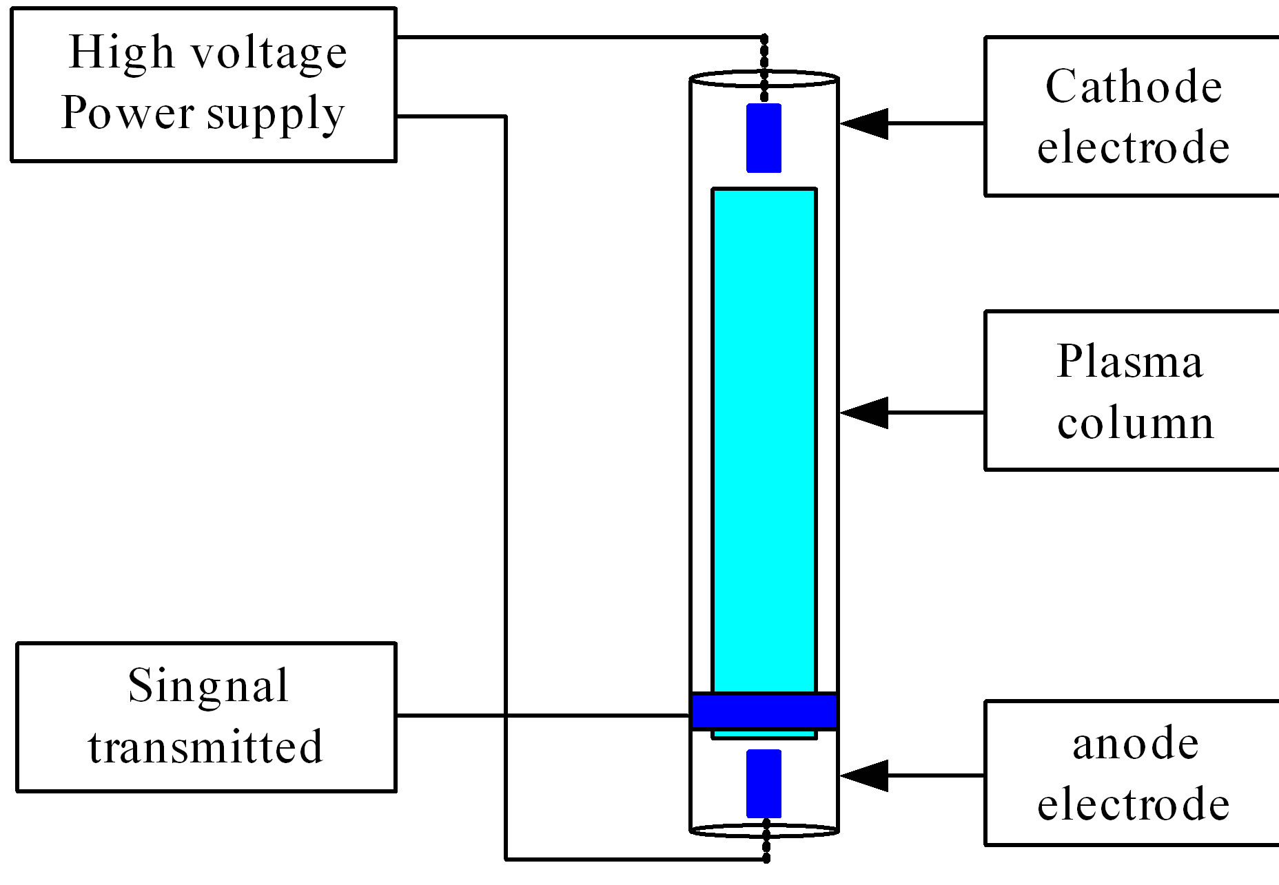
Figure 1. The structure of the plasma antenna excited by high voltage.
 (a)
(a) (b)
(b) (c)
(c)
Figure 2. The control circuit of plasma antenna.

Figure 3. The structure of the monopole plasma antenna excited by surface wave.
diameter and 10 mm inner diameter glass tube, and inside is filled with Ar gas. On both side of the tube are two hollow cathode type cylindrical electrodes. Two wires connect electrodes with a high voltage power supply. When the plasma is first turned on, the applied voltage has to exceed the breakdown voltage of roughly 1.5 KV, and then the discharge turns into current control mode at a fixed voltage of 800 V - 850 V. The discharge current ranges from 5A to 25A, the diameter of the plasma column is about 18 mm. The experimental setups are as shown in Figures 2 and 4. The plasma density in the tube is estimated to be about , which can be adjusted in certain degree by the AC conduction current.
In Figure 2, the control circuit of the plasma antenna is presented, the supply power of the plasma antenna can be controlled through the input voltage as illustrated in the (b) of Figure 2, (a) of Figure 2 is the outer AC circuit and its input voltage is 380 V, (b) of Figure 2 is the capacity and the high power transformer which supply the power for the AC-biased plasma antenna.
The photos of the AC-biased plasma antenna and its array are shown as (a) (b) of Figure 3, and the state of the plasma antenna can be changed through the outer circuit, thus the characteristics of the plasma antenna can be controlled through the external AC circuit.
The diagram and the experimental photos of the monopole plasma antenna excited by the surface wave are given in Figures 3 and 5. The plasma frequency of the AC-biased plasma antenna is about 8 GHz. A network analyzer is connected to two copper foils that couple the signal to the plasma antenna. The copper foils are 3 cm wide, two coupling locations were tested, at the bottom end and at the center of the tube, but only the end coupling case is presented here.
4. Experimental Analysis
4.1. Gain
In Figure 6, the gain of the AC-biased plasma antenna and the plasma antenna excited by surface wave are schematically presented, from which we can see that the AC-biased plasma antenna has a larger gain compared to the plasma antenna excited by the surface wave, when the electron-ion temperature and the density of the plasma antenna are both high.
In the Figure 7, the gain of the plasma antenna of AC-biased and the surface wave excited in the lower electron temperature are given, the plasma density of antenna and the electron temperature of plasma antenna are both low. From Figure 7, it can be found that when the frequency of signal is below 4 GHz, the plasma antenna excited by the surface wave has a larger gain, when the frequency of the signal is above 4 GHz, the
 (a)
(a) (b)
(b)
Figure 4. The plasma antenna and its array excited by AC power.


Figure 5. The monopole plasma antenna excited by the surface wave.

Figure 6. The gain of the plasma antenna AC-biased and the plasma antenna excited by the surface wave.

Figure 7. The gain of the plasma antenna AC-biased and the plasma antenna excited by the surface wave.
AC-biased plasma antenna has a larger gain. It also can be concluded that the AC-biased plasma antenna has a larger gain than that of the plasma antenna excited by the surface wave in most cases.
In Figure 8, the gain of AC-biased plasma antenna of the different excited power are given, from the results above, it can found that the different excited power will lead to the different gain of the plasma antenna, and the higher excited power can cause the higher gain of the plasma antenna, and when the power is high enough and the density of the plasma antenna changes slightly and the gain of the plasma antenna presents stable and reaches the larger value.
From the figures mentioned above, We can conclude that the plasma antenna of AC-biased and excited by the surface wave exhibit the same general trend of rising gain, especially when the frequency is above 8 GHz.
4.2. Radiation Pattern
The Figures 9 and 10 are the radiation pattern of the plasma antenna and the signal frequency is 8 GHz. From the figurers, we can see the radiation pattern of the plasma antenna of AC-biased and excited by the surface wave. The radiation pattern of the AC-biased plasma antenna has a larger gain and good direction performance, and the radiation pattern of the plasma antenna excited by the surface wave presents abnormal distribution in some directions which may caused by the non-uniform distribution of the plasma, and the energy absorbing in some part of the plasma antenna excited by the surface wave also leads the abnormality of the radiation pattern.
The Figure 11 is the radiation pattern of AC-biased plasma antenna of the different AC power, and with the increase of power, and presents good directional performance. So if we control the excited power properly, the radiation pattern of the plasma antenna can be controlled and it can be used in the communication system.

Figure 8. The gain of the plasma antenna AC-biased.

Figure 9. The radiation pattern of the plasma antenna.

Figure 10. The radiation pattern of the plasma antenna.

Figure 11. The radiation pattern of the plasma antenna.
5. Conclusion
The characteristic of the AC-biased plasma antenna and the plasma antenna excited by the surface wave has been presented. A new technique for the experimental characterization of plasma antenna has also been developed. The experimental results obtained, the radiation patterns of antennas are basically omni-directional, but because the 60 cm antenna size is larger than the quite zone of the anechoic chamber at this frequency, the radiation patterns show typical sharp edges in some directions. Plasma antenna shows positive gain when the signal frequency is over the plasma characteristic frequency. The gain of AC-biased plasma antenna is larger than the plasma antenna excited by the surface wave.
6. Acknowledgements
This project is supported by the National Defense Research Fund of China.
REFERENCES
- M. Moisan and Z. J. Zakrzewski, “Plasma Sources Based on the Propagation of Electromagnetic Surface Waves,” Journal of Physics D: Applied Physics, Vol. 24, No. 7, 1991, pp. 1025-1048. doi:10.1088/0022-3727/24/7/001
- J. P. Rayner, A. P. Whichello and A. D. Cheetham, “Physical Characteristics of Plasma Antennas,” IEEE Transactions on Plasma Science, Vol. 32, No. 1, 2004, pp. 269- 281. doi:10.1109/TPS.2004.826019
- G. Cerri, R. De Leo, V. Mariani Primiani and P. Russo, “Measurement of the Properties of a Plasma Column Used as a Radiated Element,” IEEE Transactions on IMT, Vol. 57, No. 2, 2008, pp. 242-247.
- W. Shen, J. E. Scharer, N. T. Lam, B. G. Porter and K. L. Kelly, “Properties of a Vacuum Ultraviolet Laser Created Plasma Sheet for a Microwave Reflector,” Journal of Applied Physics, Vol. 78, No. 12, 1995, pp. 6974-6979. doi:10.1063/1.360773
- K. L. Kelly, J. E. Scharer, G. Ding, M. Bettenhausen and S. P. Kuo, “Microwave Reflections from a Vacuum Ultraviolet Laser Produced Plasma Sheet,” Journal of Applied Physics, Vol. 85, No. 1, 1999, pp. 63-68. doi:10.1063/1.369392
- W. L. Kang, M. Rader and I. Alexeff, “A Conceptual Study of Stealth Plasma Antenna,” Proceedings of the 1996 IEEE International Conference on Plasma Science, Boston, 3-5 June 1996, p. 261. doi:10.1109/PLASMA.1996.551505
- W. Alexeff, L. Kang, M. Rader, et al., “A Plasma Stealth Antenna for the US Navy,” Proceedings of the 1998 IEEE International Conference on Plasma Science, Raleigh, 1-4 June 1998, p. 277.
- M. Moisan and Z. J. Zakrzewski, “Plasma Sources Based on the Propagation of Electromagnetic Surface Waves,” Journal of Physics D: Applied Physics, Vol. 24, No. 7, 1991, pp. 1025-2048. doi:10.1088/0022-3727/24/7/001
- R. F. Fernsler, W. M. Manheimer, R. A. Meger, J. Mathew, D. P. Murphy, R. E. Pechacek and J. A. Gregor, “Production of Large Area Plasmas by Electron Beams,” Physics of Plasmas, Vol. 5, No. 5, 1998, pp. 2137-2144. doi:10.1063/1.872886
- W. M. Manheimer, R. F. Fernsler and M. S. Gitlin, “High Power, Fast, Microwave Components Based on Beam Generated Plasmas,” IEEE Transactions on Plasma Science, Vol. 26, No. 5, 1998, pp. 1543-1555. doi:10.1109/27.736059
- D. P. Murphy, R. F. Fernsler, R. E. Pechacek and R. A. Meger, “Microwave Emission from Plasmas Produced by Magnetically Confined Electron Beams,” IEEE Transactions on Plasma Science, Vol. 30, No. 1, 2002, pp. 436- 441. doi:10.1109/TPS.2002.1003893
- G. G. Borg, J. H. Harris, D. G. Miljak, et al., “Application of Plasma Columns to Radio—Frequency Antennas,” Applied Physics Letters, Vol. 74, No. 22, 1999, pp. 3272-3274. doi:10.1063/1.123317
- G. G. Borg, J. H. Harris, D. G. Miljak and N. M. Martin, “Application of Plasma Columns to Radio Frequency Antennas,” Applied Physics Letters, Vol. 74, No. 22, 1999, pp. 3272-3274. doi:10.1063/1.123317
- G. G. Borg, J. H. Harris, N. M. Martin, D. Thorncraft, R. Milliken, D. G. Miljak, B. Kwan, T. Ng and J. Kircher, “Plasmas as Antennas: Theory, Experiment and Applications,” Physics of Plasmas, Vol. 7, No. 5, 2000, pp. 2198- 2202. doi:10.1063/1.874041
- J. W. Lv, Z. L. Chen and Y. S. Li, “Two-Dimensional Models of the Cylindrical Monopole Plasma Antenna Excited by the Surface Wave,” WSEAS Transactions on Communication, Vol. 10, No. 11, 2011, pp. 323-330.
- J. W. Lv, Z. L. Chen and Y. S. Li, “A Self-Consistent Model on Cylindrical Monopole Plasma Antenna Excited by Surface Wave Based on the Maxwell-Boltzmann Equation,” Journal of Electromagnetic Application and Analysis, Vol. 3, No. 8, 2011, pp. 297-304.