Journal of Electromagnetic Analysis and Applications
Vol. 3 No. 12 (2011) , Article ID: 16518 , 22 pages DOI:10.4236/jemaa.2011.312077
Performance Description of Brushless Doubly-Fed Induction Machine in Its Asynchronous and Variable Speed Synchronous Modes
![]()
1Department of Electrical Engineering, Sharif University of Technology, Tehran, Iran; 2Electrical Engineering Division, University of Cambridge, Cambridge, United Kingdom.
E-mail: h_gorgin@ee.sharif.edu, oraee@sharif.edu, ram1@eng.cam.uk
Received September 19th, 2011; revised October 20th, 2011; accepted October 28th, 2011.
Keywords: Brushless doubly fed machine (BDFM), cascade induction mode, direct and indirect cross coupling, nested loop rotor, simple induction mode, spatial harmonic, synchronous mode
ABSTRACT
Brushless Doubly-Fed Machine has attracted considerable attention in recent years due to its advantages. It has the robustness of the squirrel cage induction machine, and the speed and power factor controllability of the synchronous machine as well as the absence of brushes and slip rings, and using a fractionally rated frequency converter. Hence, there are considerable benefits over the conventional machines, when the machine is applied to applications such as a wind turbine generator or high power adjustable speed drive. However, these benefits are obtained in slightly more complex structure, higher cost and larger dimensions in comparison to the conventional induction machine. This paper presents fundamental aspects of the three modes of operation of brushless doubly fed machine, i.e. simple induction mode, cascade induction mode, and synchronous mode. The investigation is performed by analyzing the spatial harmonic contents of the rotor magnetic flux density. The direct cross couplings between stator and rotor fields as well as, indirect cross coupling between stator fields by the special rotor of this machine is described. Furthermore, loss analysis of the machine in various modes is presented and the torque-speed curves for asynchronous modes are obtained. A 2-D magnetodynamic finite element model based on the D-180 4/8 pole prototype machine is extracted and simulated to verify the results.
1. Introduction
The conceptual idea of the machines with two stator windings can be traced to some publications in the 1900s [1-3]. From the stator winding point of view, dual-stator winding machines have been categorized as split-wound and self-cascaded [4]. The split-wound dual-winding machine was proposed to improve the power capability of large synchronous generators and to achieve better drive reliability resulting from its inherent redundancy [5]. The second type, the self-cascaded machine or the brushless doubly-fed machine (BDFM), with two sets of stator windings, which do not couple directly but via the intermediate action of a special rotor, was introduced by Hunt in 1907 [2]. The special rotor structure increases the manufacturing cost and the complexity of the machine and produces undesirable spatial harmonics which decrease machine efficiency. But the brushless doubly fed machine shows commercial advantages because of the fractionally rated converter, and absence of the brush gear. The major application of BDFM is in wind generation, especially in harsh conditions, where it requires lower maintenance. Furthermore, it can be used as an adjustable speed drive [6,7].
The BDFM has two balanced three-phase windings on its stator. One of them is the power winding with Pp pole pairs, which is directly connected to the grid, and the control winding with Pc pole pairs, which is connected to the grid via a bidirectional fractional rated frequency converter (Figure 1). There are some rules on the selection of the stator windings pole number to avoid electromagnetic coupling between them [8].
The rotor should couple the power and control windings magnetic fields, in the appropriate manner. There are some suggestions about the rotor configuration [9].
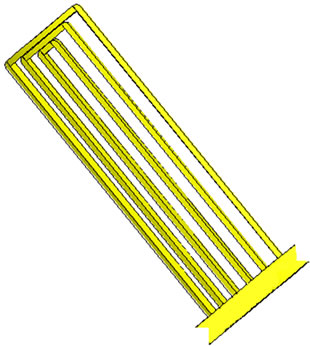
The most popular structure is nested loop rotor, which was proposed by Broadway and Burbridge [10] (Figure 2). In this structure, the rotor consists of a number of nests and some loops in each nest which are short circuited through an end ring. The number of nests should be equal to the summation of the number of power winding and control winding pole pairs to provide indirect cross coupling between the fields of the stator windings (Pr = Pp + Pc).
The modeling and performance analysis of the BDFM has been examined in many publications. However, there is no comprehensive discussion on the electromagnetic phenomena that takes place and results in the three modes of operation. An alternative formulation of BDFM operation in synchronous mode has been published recently [11]. The paper presents a precise characterization of all magnetic field components, which can be used in the machine design process and investigate the appropriate rotor configuration.
This paper presents the characteristics of the BDFM in simple induction, cascade induction and synchronous modes of operation and also, describes the direct and indirect cross coupling by simple electromagnetic relations. To simplify the analysis procedure and extraction of the relations, it is supposed that the nested loop rotor has one loop in each nest. As in the case of squirrel cage induction machine, increasing the number of rotor bars
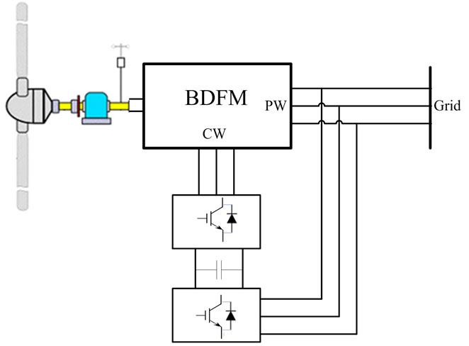
Figure 1. A wind turbine configuration based on BDFM.
 (a)
(a) (b)
(b)
Figure 2. (a) Nested loop rotor with six nests and three loops per nest; (b) One nest.
sdecreases the spatial harmonic contents of the rotor flux and its leakage inductance, and therefore, results in better performance characteristics. A 2-D magnetodynamic finite element model of the D-180 frame prototype BDFM is used for verification.
2. General Investigations
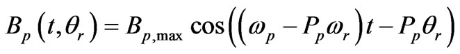
2.1. Magnetic Fields
The magnetic field density of the power winding (Bp) in its reference and in the rotor reference frames are stated in Equations (1) and (2), respectively.
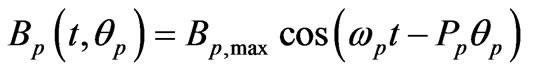 (1)
(1)
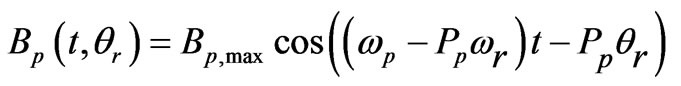 (2)
(2)
where θp and θr are the mechanical angle around the air gap in power winding and rotor reference frames, respectively. ωp and ωr represent the angular frequencies of the power winding supply and rotor, respectively.
The rotating magnetic field induces an emf in the rotor bars according to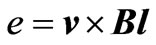 , which has the following distribution in the rotor reference frame,
 (3)
(3)
where l and r are the machine axial length and the air gap radius, respectively.
As stated, the number of rotor nests equals to Pp + Pc. The arrangement of the rotor with one loop per nest and the nest span of  are depicted in Figure 3 where Nrb represents the number of rotor slots.
The emf induced in one loop can be calculated by subtracting two induced bar emfs as Equation (4).
 (4)
(4)
With some simplifications,  can be expressed as,
 (5)
(5)

Figure 3. Nested loop rotor with one loop per nest.
where
 (6)
(6)
This voltage produces a loop current through the loop impedance,
 (7)
(7)
where Rl and Ll are the resistance and leakage inductance of the loop, respectively. The maximum value of the loop current depends only on the rotor angular velocity, that is:
 (8)
(8)
so
 (9)
(9)
where
 (10)
(10)
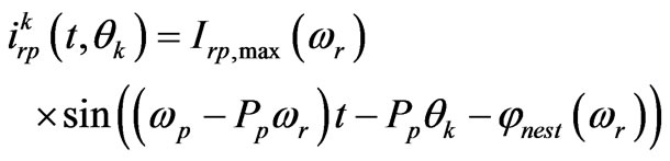
The rotor currents produce magnetic motive force in the air gap, which can be calculated by the production of the current and turn function of rotor. The distribution of the kth nest MMF as a function of the rotor angular position in the rotor reference frame is shown in Figure 4.
Fourier series representation of this spatial MMF function has the following coefficients,

Figure 4. Spatial distribution of the kth nest ampere turn.
 (11)
(11)
 (12)
(12)
Fourier series of the rotor MMF can be obtained by the summation of MMF Fourier series of all nests as (13).
 (13)
(13)
Since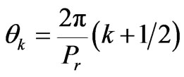 ,
,  is equivalent to the integration over
  in [0, 2π] interval.
The production of the two terms containing θk in Equation (13) can be written in summation form as,
 (14)
(14)
Substituting n = Pc + hPr, h = 0, 1, 2, ···, in the first term of the right hand side of (14), the coefficient of k will be −2π(h + 1), which eliminates the dependency on the k factor, and therefore, the result of the summation will be non zero. Similarly, if n = Pp + hPr, h = 0, 1, 2, ···, in the second term of the right hand, the coefficient of k will be 2πh, which also leads to non zero value for the summation. Hence, space harmonic orders n = Pp + hPr and n = Pc + hPr appear in the rotor produced MMF in the air gap due to power winding rotating field. All harmonics have the same time frequency. However, the rotation direction of n = Pp + hPr and n = Pc + hPr orders are in the same and the opposite direction, respectively, in comparison with the power winding flux.
Similarly, it can be shown that if the power winding is opened and in turn, the control winding is supplied, the rotor will produce an MMF with spatial harmonic orders n = Pp + hPr and n = Pc + hPr, which rotate in the opposite and same direction with respect to the control winding flux, respectively.
2.2. Direct and Indirect Cross Coupling
Among the rotor field space harmonics due to the field of the power (/control) winding, the Pp (/Pc) pole pair harmonic field couples with the power (/control) winding field. This mechanism is called “direct cross coupling”. Similarly, the rotor field harmonic which has Pc (/Pp) pole pairs due to the field of the power (/control) winding, can couple with the control (/power) winding, if they have also same time frequency. However, this mechanism is called “indirect cross coupling”.
The rotor MMF harmonics with Pp and Pc pole pairs corresponding to the power winding magnetic field are presented in Equations (15) and (16), respectively.
 (15)
(15)
 (16)
(16)
The amplitudes of these components are related just to the shaft rotational speed. Considering Equation (17), where g is the air gap width, the produced magnetic field densities can be written as Equations (18) and (19).
 (17)
(17)
 (18)
(18)
 (19)
(19)
The mechanical angular frequency of Brp,Pc(t, θr) equals (ωp − Ppωr)/Pc in the opposite direction with respect to the rotor. Hence, the field mechanical angular frequency from the control winding’s point of view is,
 (20)
(20)
Therefore,
 (21)
(21)
2.3. Induced EMF in Control Winding
To find the induced voltage in each phase of the control winding due to , first the induced emf in one coil with Nc series turn positioned at θc angle should be calculated.
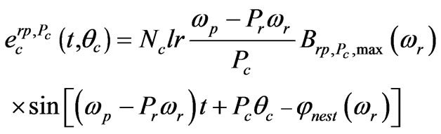 (22)
(22)
Considering Ns as the number of stator slots, the distance between two consecutive slots is 2π/Ns, and the number of slots in each pole and phase is Ns/6Pc. Considering one layer full pitch winding, the induced voltage in each phase of the control winding can be represented as Equation (23).
 (23)
(23)
It is evident from Equation (23) that the amplitude and frequency of the induced voltage are zero at the natural speed (ωr = ωn = ωp/pr). If the voltage can produce a current, the air gap flux produced by the currents for ωr < ωn and ωr > ωn will rotate in the opposite and the same direction with respect to the rotor, respectively.
3. Simple Induction Mode
Simple induction mode of operation occurs when one of the stator windings is open-circuited and the other is supplied through a three phase source. This situation can take place in converter failures, for instance. In the following analysis, it is assumed that the control winding is opened, and it is proven that the machine can act approximately like an induction machine, however with poorer performance.
3.1. Torque
In the simple induction mode, only the  component of the rotor field produces induction torque and leads the machine to operate as an induction machine. The other harmonic orders appear as rotor leakage flux with no average torque. As a result, performance of the BDFM is poorer than the squirrel cage induction machine of the same dimension. The electromagnetic torque can be calculated as follows,
 (24)
(24)
 (25)
(25)
T is a function of the rotor speed as in the case of induction machine.
3.2. Simulation Results
A magnetodynamic 2-D finite element model is extracted and simulated to verify the above discussions. This model allows simulating the machine with its special rotor bars configuration. The machine is modeled in a 2-D domain using Maxwell equations to formulate the field behavior and the finite element method (FEM) to discrete the domain. The formulation uses the magnetic vector potential as an unknown parameter, the Galerkin method to obtain the set of equations that can be solved numerically, the Euler recurrence method to discrete the temporal derivatives, and the successive approximation and Newton-Raphson method to consider the nonlinear characteristic of the magnetic material. Movement is taken into account by means of the moving band technique, the Maxwell stress tensor and the mechanical oscillation equation. The simulation details are mentioned in [12].
The power and control windings have 2 and 4 pole pairs, respectively. The rotor has 6 nests with 3 loops per nest. Other specifications of the simulated machine can be found in [8]. The rotor bars have been considered as a winding, they are connected with each other in an external electric circuit to form the nested loop rotor configuration, and it is then linked to the FE model to perform the simulations (Figure 5).
The control winding is open circuit and the power winding is supplied by a 50 Hz, 220 Vrms voltage source. The applied load torque and the machine initial speed are zero. The machine starts to rotate and reaches a speed close to the synchronous speed of the power winding.
1) Magnetic Field
2-D distribution of the flux lines, magnetic field density in the air gap and its space harmonic components during starting are shown in Figure 6, respectively. It can be seen that there are all predicted pole pairs in the air gap field, including Pc. Figure 7 shows the space harmonic spectrum of the air gap field for the steady state operation near the synchronous speed of the power winding (1500 rpm). The air gap flux density has clearly a 4 pole distribution. In fact, the speed of the power winding produced flux with respect to the rotor is very small, and therefore the emf induced in this speed is small, too. Hence, the amplitude of other space harmonic fluxes at the air gap is smaller than the start up period.
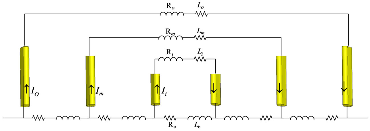
Figure 5. The configuration of rotor bars in one nest used in FE simulations.
 (a)
(a) (b)
(b) (c)
(c)
Figure 6. Space harmonic components of the air gap field at a time in starting duration of simple induction mode (a) flux distribution; (b) Air gap magnetic field vs θr; (c) Space harmonic components of the air gap field.
 (a)
(a) (b)
(b) (c)
(c)
Figure 7. Steady-state performance in simple induction mode (a) Flux distribution; (b) Air gap magnetic field vs. θr; (c) Space harmonic components of the air gap field.
2) Torque and Speed
The electromagnetic torque and speed are shown in Figures 8 and 9, respectively. The oscillatory torque before reaching steady state speed is due to coupling between the harmonic fields produced by the rotor with noticeable amplitude and the power winding fluxes.
Finite element simulation results show that the starting torque is very low in this mode and the starting procedure takes a long time compared to the induction machine. Finally, the machine reaches a speed close to its synchronous speed, i.e. 1500 rpm. In the steady state, the machine torque ripple is higher than an induction machine because of the low number of rotor bar per pole which results in higher harmonic content. The steady state produced electromagnetic torque in this mode is very low because the control winding is open and only the magnetizing current can exist, similar to a no load transformer. Figure 10 shows the torque-speed characteristic in this mode.
3) Induced EMF in the Control Winding
The induced emf in the control winding, when the shaft speed increases to the synchronous speed of the power winding from standstill, is shown in Figure 11. From Equation (23), it was predictable that rotor speed reaches the natural speed (500 rpm), frequency and consequently, amplitude of the emf become zero. Then both these parameters start to increase again by increasing the rotor speed from the natural speed; however, the amplitude decreases under steady-state operation, because the emf induced in the rotor becomes very low, as mentioned

Figure 8. Electromagnetic torque in the simple induction mode of operation.

Figure 9. Rotor speed in induction mode operation.
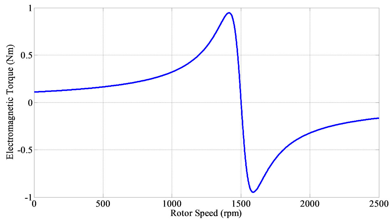
Figure 10. Torque-speed characteristic of the induction mode operation.

Figure 11. Induced emf in the control winding in simple induction mode when the shaft speed increases to the synchronous speed of the power winding from standstill.
before. According to Equation (23), the phase sequence of the induced voltage is reversed, as illustrated in Figure 12.
4) Losses
High harmonic content of the rotor flux density leads to high core loss and low efficiency. Figure 13 shows the core, rotor and stator copper losses. In the natural speed, the core loss is decreased, because of the zero speed of the Pc pole pair flux produced by the rotor with respect to the stator. Similarly, very low speed of the power winding flux with respect to the rotor leads to reduction of copper loss under steady state conditions.
3.3. Cascade Induction Mode
This mode of operation occurs when one of the stator windings are supplied, while another is short circuited. In fact, BDFM in the cascade mode can be considered as two induction machines with rotors are connected together both electrically and mechanically, and behaves as an induction machine with Pp + Pc pole pairs.
Furthermore, if both stator windings are excited, but the rotor speed is not appropriate to create indirect cross coupling between their fields and put the machine in its desirable mode of operation (synchronous mode), BDFM will operate as two separate cascade machines. This condition happens when the speed controller fails to stabilize the machine in synchronous speed. If the rotational speed of the rotor space harmonic component in response to one of the stator winding field (e.g. power winding) with the same pole pairs as the other winding (e.g. control
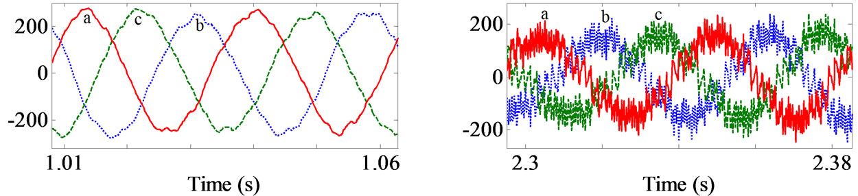
Figure 12. Phase sequence changing of the induced emf in control winding after the natural speed.

Figure 13. Core, rotor and stator copper losses in the simple induction mode.
winding), does not match the field rotating speed of that winding (control winding), the winding (control winding) is short circuited from the harmonic component point of view, and vice versa.
Supposing that the power winding is supplied and the control winding is short circuited, the  term in the rotor field, in response to the power winding field, induces an emf in the control winding. The induced voltage can be calculated by Equation (23). The control winding induced voltage can therefore be written as,
 (26)
(26)
 (27)
(27)
 (28)
(28)
The voltages generate current in shorted windings, and thus a rotating magnetic field in the air gap. The rotating field distribution, in the control winding and the rotor reference frames are presented in Equations (29) and (30), respectively.
 (29)
(29)
 (30)
(30)
The phase and amplitude of the magnetic field are functions of the rotor speed. The amplitude is zero at ωp/Pr and ωp/Pp in the control winding and the rotor reference frames, respectively. For ω < ωn the magnetic field is clockwise (negative sequence), and for ω > ωn rotates anti-clockwise (positive sequence). Initially, the machine is supposed to operate below the natural speed.
The rotor bar induced voltage due to the magnetic field of Equation (30) is in the form of,
 (31)
(31)
The induced voltage in each loop can be calculated by subtracting its two bar voltages, as follows,
 (32)
(32)
The corresponding current in the kth loop is presented in Equation (33).
 (33)
(33) The Fourier series of the MMF arises from the rotor nest current can be derived as follows,
 (34)
(34)
Production of the two terms containing θk in Equation (34) can be expanded as,
 (35)
(35) Similar to the previous section, according to Equation (35), the rotor can produce n = Pc + hPr (clockwise) and n = Pp + hPr (anti-clockwise) space harmonic components in its air gap magnetic field. It should be noted that the directions in the parenthesis are for speeds below natural speed. Otherwise, the rotation direction of the control winding magnetic field and these terms would be reversed.
For ω < ωn, the Pp pole pair harmonic of the rotor flux due to control winding field couples with the power winding field. Since they have identical direction and speed, it produces acceleration torque. However, for ω > ωn, the field rotates in the opposite direction of the power winding field, which produces braking torque. As mentioned before, for ω < ωn and ω > ωn the Pc pole pair harmonic fluxes of the rotor and control winding rotate in opposite and same direction with respect to the PP pole pair harmonic fluxes, respectively, from the stationary point of view. This is the reason why BDFM operates near natural speed in this mode, and it operates similar to an induction machine with Pp + Pc pole pairs.
The torque can be calculated similar to the previous section as Equation (36),
 (36)
(36)
As expected, the torque for ωr < ωp/Pr is positive, for ωr < ωp/Pr is negative, and for ωr = ωp/Pr is zero. Furthermore, the torque will be zero if ωr = ωp/Pp, because of zero emf induced in the rotor.
As stated, when both power and control windings are fed while rotor does not rotate at synchronous speed, there are two cascade machines with synchronous speeds of ωp/Pr and ωc/Pr. Hence, the machine operating point would be between ωc/Pr and ωp/Pr and, one of the machines will act such as an applied load to the other.
Figures 14 and 15 illustrate the torque and rotor speed, respectively, when the control winding is short-circuited. As observed, the rotor rotates near natural speed.
The magnetic flux distribution is shown in Figure 16. It can be seen that the machine has 6 poles. Furthermore, it is obvious that the air gap magnetic field contains 2 and 4 pole pair space harmonics, while other harmonics have noticeable amplitude, because the relatively high speed of the power winding with respect to the rotor leads to high flux produced by the rotor.
It is interesting to see the control winding current waveform while it is short circuited as shown in Figure 17. The control winding current amplitude and frequency are decreased when the speed increases to the natural speed, as expected.
Figure 18 shows the rotor current. The rotor current frequency (ωp − Ppωr) has been decreased with increasing rotor speed. The rotor frequency in this condition is (ωp − Ppωr)/2π = 33.33, which is depicted in Figure 19.
The machine losses are divided into core as well as

Figure 14. Electromagnetic torque in cascade mode of operation.

Figure 15. Rotor speed in cascade mode of operation.
rotor and stator copper losses, which are shown in Figure 20. In this mode, the control winding is shorted, and therefore the currents are higher than simple induction mode. However, due to zero load torque, the steady state current and its corresponding losses are small.
The rotation speed is related to the load torque as in the case of conventional induction machine. Figures 21 and 22 show the electromagnetic torque and rotor speed in −10 and +20 Nm load torques, respectively.
The torque-speed characteristic in cascade mode of operation (ωn = 500 rpm) is depicted in Figure 23 using Equation (36). The two operating points of Figures 21 and 22 which are indicated on this figure confirm the accuracy of the analytical procedure. Furthermore, the machine behavior is like an induction machine at the speeds close to the natural speed, and motoring and generating regions are clearly observable. The maximum torque in this mode is more than 50 times greater than the simple induction mode, which is the result of the high currents that was described before.
To show that the BDFM operates in asynchronous mode when both stator windings are excited, in the next simulation, the power winding is fed by a 100 Vrms, 50 Hz and the control winding by a 220 Vrms, 30 Hz voltage sources. As mentioned before, when the machine does not operate in synchronous mode, it works as two cascade machines, and the machine becomes stable between the natural speeds of two aforementioned machines. The
 (a)
(a) (b)
(b)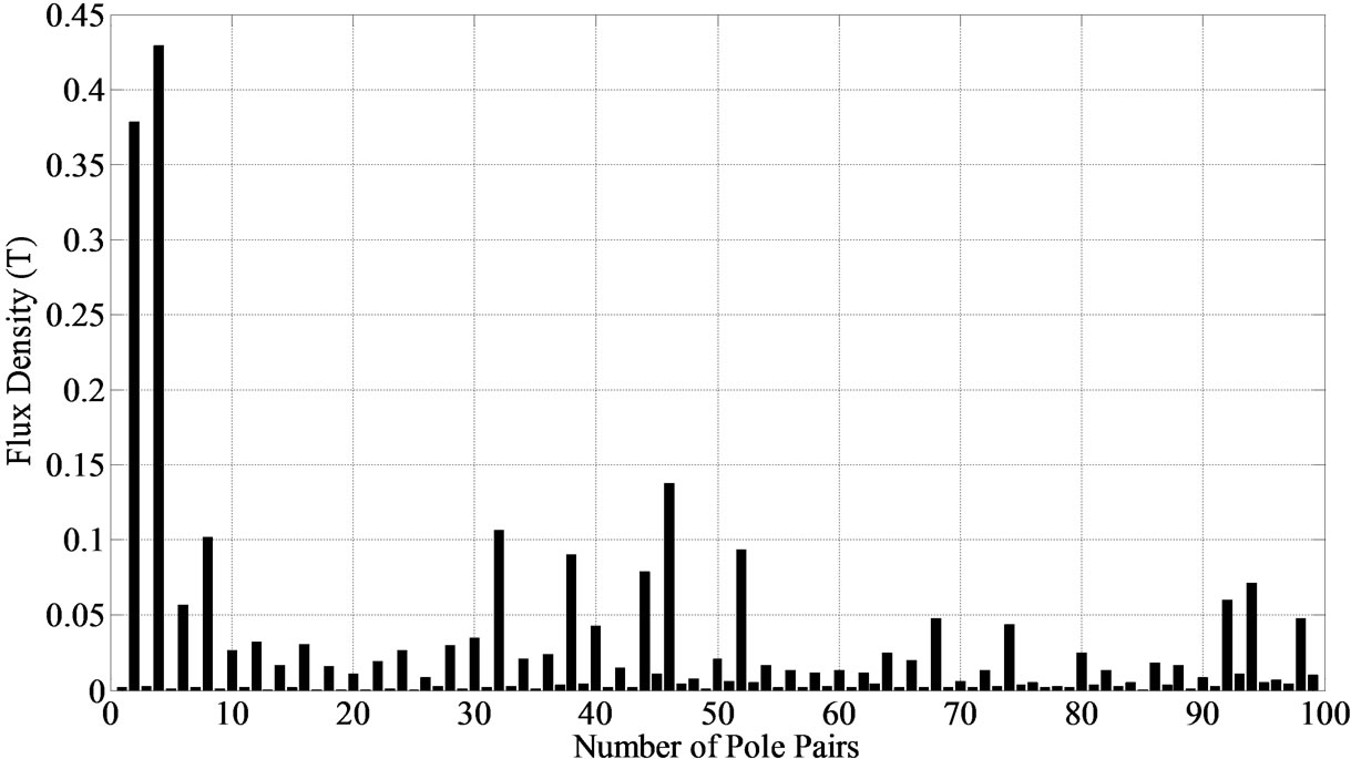 (c)
(c)
Figure 16. Steady state operation in cascade induction mode (a) Flux lines distribution; (b) Magnetic field vs. θr; (c) Space harmonic components of air gap field.

Figure 17. Control winding induced current in cascade mode.

Figure 18. Rotor nest current.
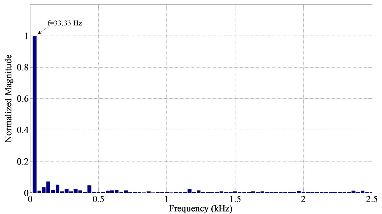
Figure 19. Outer loop current FFT of a nest.

Figure 20. Core, rotor solid, and stator stranded losses.
 (a)
(a) (b)
(b)
Figure 21. (a) Electromagnetic torque; (b) Speed in the cascade mode with −10 Nm load.
 (a)
(a) (b)
(b)
Figure 22. (a) Electromagnetic torque; (b) Speed in the cascade mode with +20 Nm load.

Figure 23. Torque-speed in cascade mode operation.
rotor speed in this condition is shown in Figure 24.
4. Synchronous Mode
The In this mode, the stator windings are supplied, and the rotor rotates at a certain speed, which enable it to couple the two stator windings magnetic fields. It should be noted that the two stator windings do not have any direct coupling with each other because of their different pole numbers. Initially, it is assumed that the machine operates as a motor. The two stator windings produce two magnetic fields in the air gap in the form of Equations (37) and (38),
 (37)
(37)
 (38)
(38)
Each stator magnetic field induces voltage and current in the rotor loops. These currents generate rotor flux in the air gap. The rotor flux in response to each stator field consists of two main terms with Pp and Pc pole pairs as well as other harmonics with relatively small amplitude. The part of the rotor field in response to one of the stator windings field couples with the field of the other stator winding with same pole pairs and produce electromagnetic torque. In fact, the fields of the two stator windings couple with each other indirectly through the rotor, which rotates at a specific speed. The second main part of the rotor flux due to one of the stator winding has equal pole pair numbers to it and couples with the field of that winding. So, there are synchronous and induction torques in this mode of operation. However, if the time frequency of the part of the rotor fluxes corresponding to a stator winding does not match the other stator filed frequency, no average torque will be produced, and the BDFM will work as two cascaded machines in one frame, which was described earlier.
The rotor magnetic field corresponding to the power winding field, which has Pc pole pairs, and control winding field in the rotor reference frame are stated in Equations (39) and (40), respectively.
 (39)
(39)
 (40)
(40)
The coupling of these two fields occurs, when the mechanical rotating speeds are equal. The mechanical speed of  is
is  in clockwise direction, and the speed of
  is
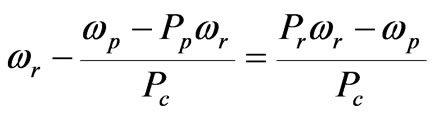
is  in anticlockwise direction. To provide cross coupling criteria between them, the following equality should be satisfied,
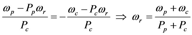 (41)
(41)
Synchronous speed can be obtained by equalization of mechanical speed of the power winding field and the part of rotor field produced in response to the control winding, which has Pp pole pair.
In synchronous mode, the torque is sum of the induction torque, which is produced due to the existence of direct couplings, and synchronous torque, resulting from the indirect cross coupling process.

Figure 24. Rotor speed.
 (42)
(42)
 (43)
(43)
where θc0 is the phase difference between the power and control windings in stator stationary reference frame.
 (44)
(44)
 (45)
(45)
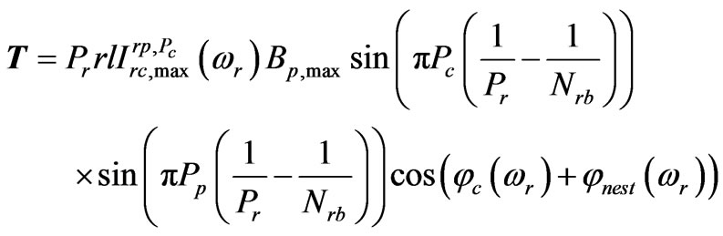
The produced torque due to the coupling between the power winding field and Pp pole pair part of the rotor field, which is produced in response to the power winding field (power winding direct coupling), is:
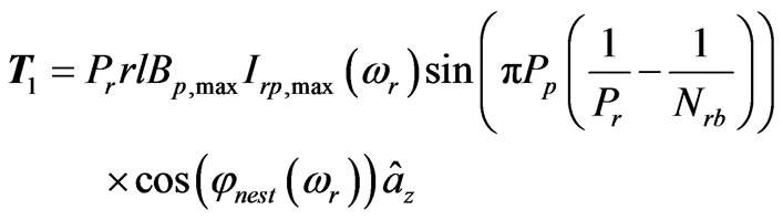 (46)
(46)
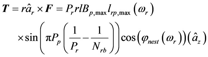
The rotor shaft applied force due to coupling of the power winding field and Pp pole pair part of the rotor field corresponding to the control winding field (control winding to power winding indirect cross coupling) can be calculated as,
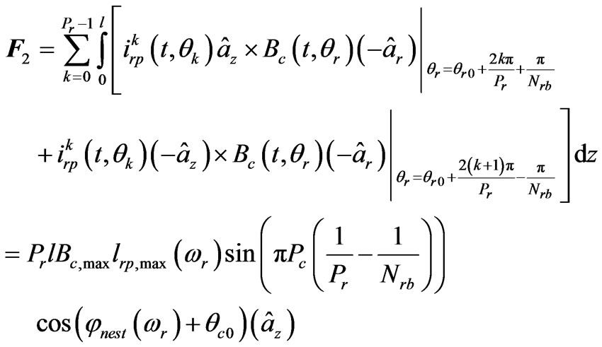 (47)
(47)
The resulting torque from this electromagnetic force can be evaluated from Equation (48).
 (48)
(48)
Also, the torque related to coupling between the control winding field and Pc pole pair part of the rotor field corresponding to control winding field (control winding direct coupling) is,
 (49)
(49)
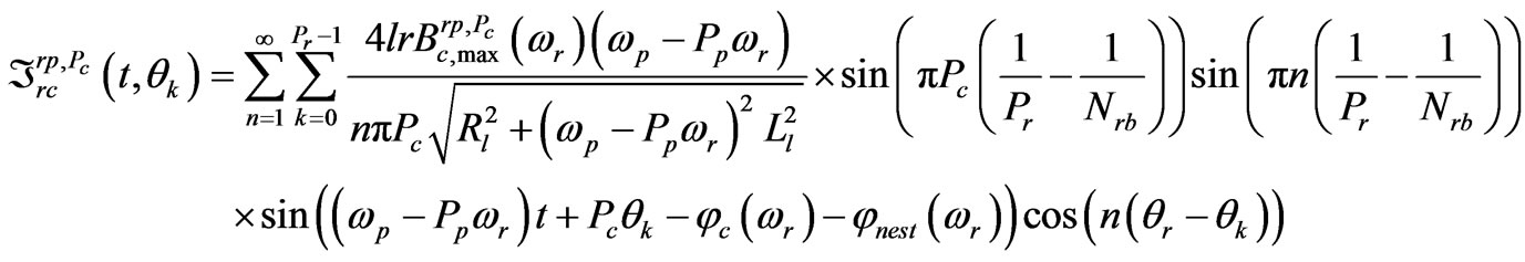
Finally, the force applied to rotor shaft and its torque due to coupling of the control winding field and Pc pole pair component of the rotor field corresponding to the power winding field (power winding to control winding indirect cross coupling) can be calculated as follows,
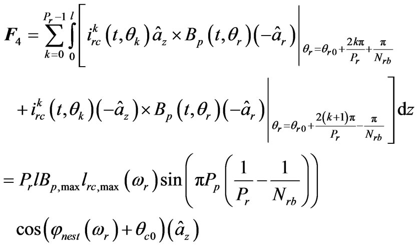 (50)
(50)
 (51)
(51)
Clearly, the total torque is equal to summation of T1 to T4.
To simulate synchronous mode, the stator power winding is fed by a 220 Vrms, 50 Hz, and the control winding by a 100 Vrms, 30 Hz voltage source. By regulating the load torque, the machine will be stabilized and rotate at the synchronous speed i.e. 800 rpm.
Figure 25 shows the air gap magnetic field, which has 6 poles distribution. It can be seen that the air gap magnetic flux density contains Pp and Pc components, i.e. harmonic orders of 2 and 4. High harmonic content of the air gap is acceptable, because both the stator windings are supplied and the rotor produces the fluxes in response to them. It should be noted that the stator fluxes electrical speeds with respect to the rotor are same and not small in general.
Figures 26 and 27 show the electromagnetic torque and speed, respectively.
Figure 28 shows the BDFM core, rotor, and stator copper losses. The copper losses are smaller than the cascaded induction mode. This is due to non-zero control winding voltage which results in fewer currents in the stator and rotor.
If the wind power leads the shaft to rotate at the speed of ωr when the BDFM is used as a wind turbine genera-
 (a)
(a)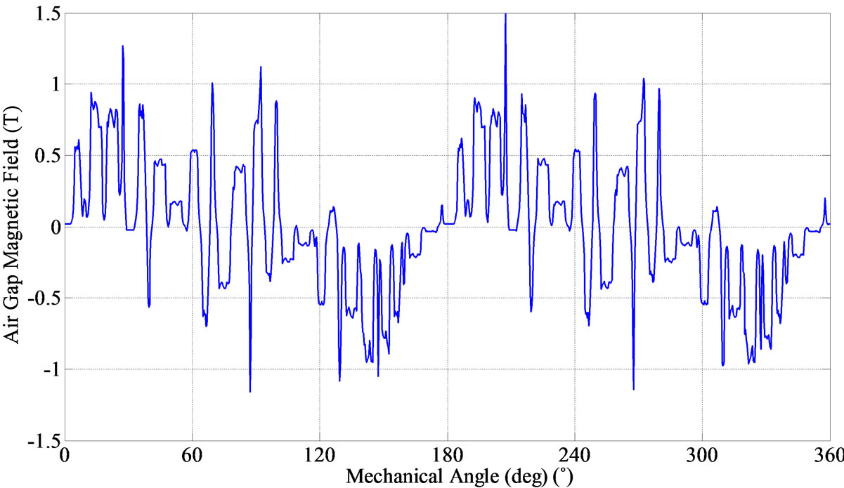 (b)
(b) (c)
(c)
Figure 25. Steady state operation in synchronous mode (a) Flux lines distribution; (b) Magnetic field vs θr; (c) Space harmonic components of flux density.

Figure 26. Electromagnetic torque in synchronous mode operation.

Figure 27. Rotor speed in synchronous mode operation.

Figure 28. Losses in synchronous mode operation.
tor, the frequency and amplitude of the induced voltage in power winding, which is directly connected to the grid, must remain fixed in spite of the wind speed variation, by changing the control winding frequency according to ωc = Prωr − ωp.
When BDFM is used as a wind turbine generator, the frequency of control winding should be regulated equal to ωc = Prωr −ωp to achieve the desired rotor speed which results in maximum power tracking from the wind.
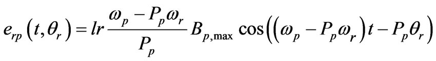
The control winding rotating field induces voltage and currents in the rotor loops, and acts similar to the field winding of the conventional synchronous machine. The rotor induced currents produce the rotor air gap flux with Pp + hPr and Pc + hPr space harmonic orders. The rotor field harmonic with Pp pole pairs induces a voltage in power winding according to the following equations,
 (52)
(52)
 (53)
(53)
 (54)
(54)
 (55)
(55)
Hence, the amplitude and phase of the induced emf in power winding is directly dictated by the control winding voltage via converter. Then, the active and reactive power flow between power winding and grid can be controlled by its phase and amplitude, respectively.
For generating operation simulation, the machine’s shaft rotates at fixed speed of 800 rpm and the control winding is excited via a 30 Hz source. The induced emf in the power winding has a 50 Hz oscillation as shown in Figure 29.
5. Conclusions
Brushless doubly-fed machine has an interesting but slightly complex structure and performance with desirable characteristic in variable speed applications such as wind turbines. A comprehensive and complete analytical study of the three modes of operation of BDFM is presented based on simple electromagnetic relations. The mechanism of direct and indirect cross couplings for each mode is explained in details and simulated by means of a 2D magnetodynamic finite element model. The components of machine losses are obtained by FEM for each mode and their behavior with speed variation are explained. Also, the variations of losses portions are compared in three modes of operation. The torque-speed characteristics of asynchronous modes are depicted and the behavior compared with each other. Furthermore, the spatial harmonics in the air gap in three modes are illustrated and described. The performance of BDFM in synchronous mode relies on the pole number changing action by its nested loop rotor while the control winding field can affect the active and reactive powers of the PW. But the intermediate action of the rotor to change the pole pairs produces many unwanted space harmonics

Figure 29. Induced emf in power winding at steady state operation as generator.
causing undesirable results in the machine behavior, for instance, increase iron loss, torque ripples, magnetizing currents, etc. Therefore, optimizing the structure of the machine is necessary to make it commercially applicable and bring it into industrial use.
REFERENCES
- F. Lydall, “Improvement in Polyphase Induction Motors,” British Patent 16839, July 1902.
- L. J. Hunt, “A New Type of Induction Machines,” J. IEE, Vol. 39, 1907, pp. 648-677.
- F. Creedy, “Some Development in Multi-Speed Cascade Induction Motors,” Journal of the Institution of Electrical Engineers, Vol. 59, No. 301, 1921, pp. 511-532.
- A. R. Munoz and T. A. Lipo, “Dual Stator Winding Induction Machine Drive,” IEEE Transactions on Industry Applications, Vol. 36, No. 5, 2000, pp. 1369-1379. doi:10.1109/28.871286
- Z. Wu and O. Ojo, “Coupled-Circuit Model Simulation and Airgap-Field Calculation of a Dual Stator Winding Induction Machine,” IEE Proceedings Electric Power Applications, Vol. 153, No. 3, 2006, pp. 387-400. doi:10.1049/ip-epa:20050466
- A. K. Wallace, R. Spee and H. K. Lauw, “The Potential of Brushless Doublyfed Machines for Adjustable Speed Drives,” Conference Record of Pulps and Paper Industry Technical Conference: IEEE Industry Application Society, Seattle, 20-22 June 1990, pp. 45-50.
- C. S. Brune, R. Spee and A. K. Wallace, “Experimental Evaluation of a Variable-Speed, Doubly-Fed Wind-Power Generation System,” IEEE Transactions on Industry Applications, Vol. 30, No. 3, 1994, pp. 648-655. doi:10.1109/28.293713
- P. C. Roberts, “A Study of Brushless Doubly-Fed (Induction) Machines,” Ph.D. Thesis, University of Cambridge, Cambridge, 2004.
- P. J. Tavner, R. A. McMahon, P. C. Roberts, E. AbdiJalebi, X. Wang, M. Jagiela and T. Chick, “Rotor & Design Performance for a BDFM,” Proceedings 17th International Conference on Electrical Machines (ICEM), Paper No. 439, Chania, 2-5 September 2006.
- A. R. W. Broadway and L. Burbridge, “Self-Cascade Machine: A Low Speed Motor or High Frequency Brushless Alternator,” Proceedings of the Institution of Electrical Engineers, Vol. 117, No. 7, 1974, pp. 1529-1535. doi:10.1049/piee.1974.0317
- F. Blazquez, C. Veganzones, D. Ramirez and C. Platero, “Characterization of the Rotor Magnetic Field in a Brushless Doubly-Fed Induction Machine,” IEEE Transactions on Energy Conversion, vol. 24, no. 3, 2009, pp. 599-607. doi:10.1109/TEC.2009.2025345
- H. Gorginpour, B. Jandaghi and H. Oraee, “Finite Element Analysis of Brushless Doubly Fed Machine under Stator Winding Faults,” 2nd Power Electronics, Drive Systems and Technologies Conference (PEDSTC), Tehran, 16-17 February 2011, pp. 169-174.