Journal of Power and Energy Engineering
Vol.05 No.09(2017), Article ID:78935,18 pages
10.4236/jpee.2017.59002
A Review on Industrial Applications of Z-Source Inverter
Nimrah Saeed, Anas Ibrar, Aimen Saeed
Shanghai Jiao Tong University, Shanghai, China

Copyright © 2017 by authors and Scientific Research Publishing Inc.
This work is licensed under the Creative Commons Attribution International License (CC BY 4.0).
http://creativecommons.org/licenses/by/4.0/


Received: June 13, 2017; Accepted: September 3, 2017; Published: September 6, 2017
ABSTRACT
Nowadays, Z-source inverters (ZSI) are one of the most emerging topologies in field of power electronics. This paper deals with brief review of Z-source inverter, comprehensive study of its various topologies and significance of ZSI in modern industry. Different PWM techniques are used to obtain wider modulation range and easier real time implementation. This paper provides a systematic reference for future scientists for further development and advancement of ZSI.
Keywords:
Boost Factor, Impedance Network, Shoot Through State, PWM Control Methods, Z-Source Inverter

1. Introduction
Voltage and current source inverters (VSI and CSI) have broad range of industrial applications such as their use in special power supplies, hybrid electric vehicles, distributed power systems and many more. Still they have many limitations because of rapid increase in inventions like reliability issues and narrow voltage range. Moreover, they can behave as buck or boost inverter at a time. Renewable energy resources like offshore wind farms or photovoltaic cell generation require a converter system to convert DC into AC voltage. In traditional converter systems, transformers are used to increase the output voltage. High cost is needed to implement the line transformer. Moreover, it causes noise pollution and has tremendous size. Transformers can be replaced by voltage or current source inverters [1] . To overcome the aforementioned issues a novel topology named Z-source inverter was proposed in 2002 by F. Z. Peng.
Z-source inverter has a unique impedance network, capacitors and and inductors and are connected in X-shape for coupling the power source with main circuit of inverter as shown in Figure 1. The basic impedance source network is the combination of two linear energy storage elements i.e. L and C. However, to improve the performance of the circuit, different configurations of network are possible with the addition of non-linear elements such as diodes or switches into the impedance network.
Boost factor B of this topology can be defined as
(1)
D is duty ratio and is interval of shoot through zero state. Modulation index M of Z-source inverter is
(2)
where, M is the ratio of amplitude of modulation waveform and carrier waveform [2] . The concept of Z-source can be applied to all power conversions. Furthermore, they can be divided into two level and multilevel topologies or isolated and non-isolated inverters. Z-source inverter has wide variety of voltage range (between 0 and ∞) because of its unique characteristics of buck-boost capability. Circuit diagram of Z-source inverter during shoot through and active states is shown in Figure 2. During shoot through state, output terminals of network are shorted by a switch, which reverse-bias the diode in impedance network. In active stage, stored energy of inductors and capacitors is transmitted to the load.
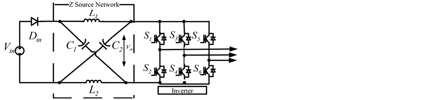
Figure 1. Basic topology of Z-source inverter.

Figure 2. Shoot through and active state.
Several topologies using different impedance source and their industrial applications have been presented in this paper. The aim of this research is to survey the Z-source topology briefly and to concentrate on its diverse industrial applications. Also, preferences of Z-source inverter over customary inverters for different applications are examined.
The rest of paper is divided into five sections. Section 2 presents related work. Applications of Z-source inverter are introduced in Section 3, simulations and discussion in Section 4 and conclusion is drawn in Section 5.
2. Related Work
In the recent past years, Z-source inverters have been the focus of researchers. There are several previous works related to this topic, some of them are presented in this section.
Miao Zhu et al. [2] proposed a new switched inductor Z-source impedance network to couple the inverter main circuit with low voltage energy source. This inverter can increase the inversion capability to improve the traditional Z source inverter. F.Z. Peng [3] did a quality work on Z-source inverter. He focused on an example of fuel cell to portray its working principle.
M. Adamowicz and S. Diva et al. [4] presented Trans-Z-source inverters, they proposed two new impedance networks i.e. LCCT (inductor-capacitor-capacitor- transformer) and LCCT-qz-source. LCCT holds two capacitors connected in series with transformer to prevent the transformer core by blocking DC current while LCCT-qz-source contains one capacitor and combine the characteristics of T-source and qz-source impedance network. Ali Mostaan et al. [5] developed a novel T-Z source inverter in which inductors of traditional Z-source impedance networks are replaced with transformers to increase its voltage gain, which is possible by decreasing turns ratio of transformer. S.M. Dehghan et al. proposed a topology of Z-source inverter with two dc inputs and two ac outputs. This inverter can control frequency, amplitude, current of dc input and phase of ac output. Moreover, the utmost point of preference of this inverter is that its outputs remain operating regardless of the possibility that one of the inputs is not available [6] . A. Pattanaphol et al. [7] used Z-source inverter to figure out the shading issue of photovoltaic cell. Po Xu et al. [8] introduced Z-source inverter for grid associated photovoltaic systems. To obtain the sought AC output of PV system, DC input is controlled through shoot through state of Z-source network. Additionally, they controlled the sinusoidal index to guarantee that system is working in unit power factor.
Omar Ellabban et al. [9] proposed a technique to control the speed of motor using bidirectional Z-source inverter. They likewise exhibited a strategy to control AC current for connecting inverter with grid during charging and discharging mode of battery. R. Senthikumar et al. projected a Z-source inverter for uninterruptible power supply (UPS) applications. By using this topology EMI immunity and reliability of inverter increases and power conversion is possible in single stage [10] . Z-source nine switched inverter is proposed by U. Supatti et al. in [11] for hybrid battery gasoline vehicles. Z-source network helps to maintain dc link voltage greater than terminal voltage. It can operate as a boost inverter when battery is in state of discharge otherwise it will be a buck inverter.
Above mentioned valuable works help to visualized the importance of Z-source inverter over conventional inverter. Working principle of ZSI is described in next section and role of Z-source inverter in different industrial applications are presented in this paper.
3. Applications of Z-Source Inverter
There are numerous industrial applications of Z-source inverter. Some of them are stated in rest of the paper.
3.1. Adjustable Speed Drives
Adjustable speed or motor drives use Z-source inverter to overcome the restrictions of VSI. An inductor is normally used in voltage source inverter to enhance the power factor but still it has complications like voltage sag, line harmonics and limited obtainable output voltage [12] [13] . Main circuit configurations of traditional and Z-source ASD system are shown in Figure 3.
It is clear from comparison of above figures that
1) Z-source ASD system has small capacitors connected with diodes at rectifier-bridge contrary to conventional ASD scheme.
2) In Z-source ASD systems Z-source impedance network connects rectifier with three phase inverter while an inductor is utilized as a part of traditional ASD framework for this reason.
In Z-source ASD systems voltage may increase due to line inductance during shoot through state that’s why capacitors are used with diodes. Only those phases that have maximum potential difference can conduct the current from AC line to DC side. Therefore, diodes of rectifier-bridge reverse biased and turned off. The remaining diodes direct and convey current in active stage, which
 (a)
(a) (b)
(b)
Figure 3. (a) Traditional ASD systems; (b) Z-source ASD systems [9] .
usually discontinue conducting in traditional ASD system relying on voltage level of capacitor. During zero state the two diodes conducts inductor current and reduce the harmonic reduction, while in shoot through state, rectifier-bridge has no association with AC line because leading diodes turned off. In [14] , relationships for shoot through states and capacitor voltage are expressed as
(3)
(4)
(5)
When, boost factor is more than 1, is explicated as
(6)
where, B is known as boost factor, is line to line rms value of generator, is DC voltage source of rectifier and is voltage across the capacitors ( ). In nut shell, Z-source ASD framework has numerous points of interest over conventional motor drive systems. It prevents the system from voltage sags, diminish the harmonic current and any required output current can also be obtained.
3.2. Offshore Wind Energy
More than 100 GW can be obtained from wind energy throughout the world. Offshore wind farms are usually distant from demand centers. Formerly, in order to interface with power transmission networks transformers were used to require high voltage gains [15] [16] . Then to get rid of huge transformers and to reduce the cost, traditional current and voltage source converters were used. In order to further advance the quality of transmission, high voltage DC link is associated with wind farms through Z-source inverters [17] . Figure 4 shows Z-source and current source inverter used for this purpose.
The above figure clearly depicts that CSI topology is more complex than ZSI network. It includes four inverters at rectifier side and to simulate power level each CSI is connected with a generator. Additionally, switches like GTO or diodes in series with switches are required, so that they can with stand with reverse current. Thus, overall installation cost increases. VSI have fewer limitations than CSI but ZSI is the best choice for this network [18] [19] .
From (3) the boost factor for inverter used in wind energy can be derived as
(7)
 (a)
(a) (b)
(b)
Figure 4. (a) CSI for offshore wind energy; (b) ZSI for wind energy.
where,
(8)
#Math_26#, is average of shoot through duty ratio for MBC [11] .
3.3. Vehicular Applications
Nowadays, one of the greatest issues of world is preservation of energy. For this purpose, new improvements in DC-DC systems are going on, especially in field of electric vehicles.
Hybrid electric vehicle (HEV) can saves energy in many ways. They have regenerative brakes that charge the battery of vehicle by converting its kinetic energy into electric energy. Some HEV generate electricity by rotating the shaft of generator using its own combustion engine. Plug-in hybrid electric vehicle (PHEV) combines both attributes of hybrid and electric vehicles. It has internal combustion engine of HEV and like electric vehicles a plug to connect with the external electric power source. PHEV use batteries that are rechargeable.
Hybrid electric vehicles can be classified into three categories i.e. series, parallel and parallel-series hybrid. In series hybrid, internal combustion engine (ICE) drives generator which charge the battery to give power to inverter which in turn can drive the motor. So, in this topology mechanical energy is converted into electrical energy and then again into mechanical energy to drive the vehicle. In parallel hybrid, wheel is directly driven by ICE. The generator/motor is also coupled with ICE, which can provide or retrieve the power, as required. To take advantage of both topologies, both configurations are combined in series-parallel hybrid system.
The major power converters used in these topologies were PWM inverters or DC-DC boosted PWM inverter. Traditional PWM inverter should be large enough to handle the voltage variations of battery. Boosted PWM inverter has an extra DC-DC stage to overcome this problem but reliability of system reduces due to this stage and it also increases the complexity and cost of system [20] [21] [22] . Currently, Z-source inverter is used to overcome the disadvantages of conventional inverters.
Boost factor during shoot through state in ZSI can be defined as [23]
(9)
where, and is time interval during switching state for shoot-through and non-shoot through states and is the duty cycle.
In [24] bidirectional Z-source inverter (BZSI) based model of HEV and PHEV are suggested as depicted in Figure 5. With the use of BZSI, speed of induction motor (IM) for HEV can be controlled more efficiently. Moreover, as BZSI can be charged at night thus, bidirectional battery charger of PHEV is replaced with BZSI so that it can be used in peak demand hours.
The proposed models can extend the productivity of the vehicle. Production cost can be reduced by implementation of these models because less number of components is used in ZSI systems as compared to other topologies.
3.4. Photovoltaic Cell
A photovoltaic (PV) cell, also called the solar cell converts the solar energy into electrical energy. Use of photovoltaic systems is increasing day by day due to its
 (a)
(a) (b)
(b)
Figure 5. (a) ZSI for HEV; (b) ZSI for PHEV.
numerous advantages. Solar modules are now used to provide electricity for residential as well as for commercial purposes [25] . PV cells are connected in parallel and series to form a module and then many modules combine together to form a panel [26] . For development less costly and highly efficient PV systems, maximum power point tracker (MPPT) algorithm has been proposed. Mostly the inverter system connected with PV array is composed of MPPT, boosting circuit and a filter which connect the load with DC source [27] [28] .
In photovoltaic cell generation plants, to convert the AC voltage into DC ZSI are best choice. They can boost the required voltage and decrease the overall size of converter system. In conventional converter systems, 20 kW inverter is needed for 10 kW photovoltaic system. KVA requirement of ZSI is minimal. The proposed model is shown in Figure 6. By utilizing this framework, 10 kW inverter is needed for a 10 kW PV system, which means KVA rating remains the same [29] .
Boost factor for simple boost control method can be determined as,
(10)
For maximum boost control system [30] ,
(11)
Traditional converters have many challenges regarding control and modulation strategy, which can be overcome by using Z-source inverter.
3.5. Uninterruptible Power Supply Application
An uninterruptible power supply (UPS) provides power to the load when main grid fails. Transformers or DC-DC converters are used to step up the voltage in ordinary UPS [31] .
Z-source inverter can provide higher peak to peak output voltage than traditional inverters. ZSI along with LC output filter can be used to reduce the voltage harmonics of UPS system caused by non-linear and unbalanced load. Figure 7 displays the proposed topology for this purpose [32] [33] . The latest bi-directional topology is proposed in [34] in which Z-source inverter is used to buck or boost the output voltage. Figure 8 shows the circuit diagram of UPS system.
The recommended system possesses a couple of Z-source networks and two full-bridges on both sides of the battery (with its charging mechanism). The

Figure 6. ZSI for PV systems.

Figure 7. ZSI for LC filters.

Figure 8. UPS system with Z-source network.
bridge on the left side of the battery rectifies the main AC voltage and then the Z-source network following it will maintain its power factor, then the second Z-source network boost or reduce the voltage and permit it to other bridge, which act as an inverter and again converts the DC voltage into AC. When main power supply dies, battery supplies power to the circuit according to its potential and UPS provides voltage to the load. Output voltage of inverter can be determined as
(12)
Hence, by using Z-source network any phase legs can be short circuited to allow the boost up ability of inverter and no dead time is compulsory due to this special feature of ZSI.
3.6. Grid Applications
Traditional inverters are used to interface grid with distributed generation systems (DG). Their fundamental reason for existing is to convey active power to the grid. Sometimes because of inaccessibility of sources, DG systems do not devote their maximum output and in this case inverters remain idle, which may cause harmonics in output voltage [35] [36] .
In [37] DG frameworks in light of Z-source inverter is proposed to defeat the aforementioned issues. Figure 9 demonstrates the principle hardware of grid associated ZSI network.
The suggested network operates in two modes. Desired amount of power is transmitted to the grid by DG network in first mode. High pass filters are used to reduce harmonics of current in first mode while harmonics of voltage in second mode. So, 1st mode is referred as current improvement mode and 2nd as voltage improvement.

Figure 9. ZSI with grid.
Along these lines, by evacuation of harmonics of current and voltage, overall power quality is enhanced by utilizing ZSI.
3.7. Fuel Cell
Fuel cell acquires electricity through chemical reaction of oxidizing agents like oxygen and hydrogen ion. Fuel cell can just produce electricity until inputs are available. It compromises of two electrodes with a layer of electrolytes. Oxygen is sustained to cathode electrode while hydrogen fuel to anode. The electrolyte only allows positive ions to flow from anode to cathode and act as an insulator for electrons. These electrons moved to cathode side through an external electric circuit to stable the system [38] [39] [40] .
The Z-source inverter is fascinating for three fundamental reasons [41] .
1) To control the output voltage, the customary PWM inverter has only one control opportunity. However the Z-source inverter has modulation index and shoot through state.
2) Z-source inverter can buck or boost the output voltage same as other inverters with the benefit of its single stage, i.e. cost effective and less complex.
3) Reliability; Momentary shoot through state cannot destroy the inverter as for a significant period of time both devices of phase leg can be turned on.
In [42] a fuel cell configuration having a Z-source network has been depicted. From Figure 10 it is clear that the system comprises of a fuel cell, diode, Z-source network and L-C filter. Z-source inverter directly boosts the dc voltage from fuel cell by taking advantage of shoot through state. Filters are used to restrict the harmonics of output voltage of inverter.
During shoot through state, average current value through switches can be described as [43]
(13)
And average current through diode and inductor is equal to ratio of maximum power and input voltage,
(14)
3.8. Energy Storage Application
To fulfill the energy demand, continuous generation of electricity is mandatory. Without energy storage an efficient energy management is not possible.

Figure 10. Fuel cell network.
Assorted types of energy storages are needed which can make grid more reliable and productive. Electrochemical batteries and super capacitor technologies are most renowned and promising technologies nowadays. Electrochemical energy is accomplished in galvanic cell, usually its battery reagents are well defined like Pb, Ni and Cd whereas super-capacitors work on the principle of electrostatic energy storage. In super capacitors electrodes store positive and negative charges and an electric field is created [44] [45] [46] .
Anyhow, power electronics equipment is used for conversion purpose. Usually a very low single cell voltage is required for storages, therefore, VSI require other conversion stages to step down the voltage. Low frequency transformer or another DC-DC converter is normally required but they decrease the conversion efficiency and raise the cost of system.
Z-source inverter is additionally valuable for energy storage applications. For this purpose a three phase bidirectional ZSI is proposed, as demonstrated in Figure 11.
The basic topology of Z-source inverter transfers energy only in one direction i.e. DC to AC side. Three phase inverter can change the direction of current but the only difficulty is input diode, which assumes to be an imperative part in boosting of voltage. Therefore, to change ZSI into bidirectional network without evacuation of diode, anti-parallel transistors are used.
Voltage across inverter-bridge should be consistent during shoot through state, to acquire required voltage across the capacitor [47] .
(15)
3.9. Special Application
Among several applications of Z-source inverter , “Voltage sag compensation” is the most vital in light of the fact that about 92% of electrical disturbances in power system are because to voltage sag. Consequently, it is a reason of extreme economical losses. Voltage sag is actually fall of voltage amplitude, i.e. between 0.1 pu to 0.9 pu [48] .
For voltage sag compensation, dynamic voltage restorer (DVR) is the most effective device. It is used to inject an appropriate voltage quantity in series with supply [49] [50] . In conventional DVR system usually VSI topology is used to obtain voltage with less harmonics but this topology limits the capability of DVR because it steps down the output voltage. Now a day’s Z-source inverter is used to conquer this issue as it can boost the output voltage during shoot through

Figure 11. Bidirectional ZSI.
state without damaging switches of inverter. Figure 12 shows this network, which has evacuated the issue of constrained achievable output voltage [51] .
Average voltage across inductor during shoot through and non-shoot through time can be determined as
(16)
Boost factor on DC side can be defined as
(17)
where T is total time while and is time during shoot through and non-shoot through states.
4. Simulations and Discussion
Three different PWM control methods i.e. simple boost control method (SBC), maximum boost control method (MBC) and maximum constant boost control method (MCBC) are used to insert shoot through state in ZSI and to obtain wider modulation range as described in Table 1.
In SBC, the circuit turns into shoot through state when triangular wave is greater than or lower than reference line. MBC method is used to achieve reduced voltage stress and desired voltage gain. In this method, all zero states are turned into shoot through states. This control method is usually feasible for high frequency applications. In MCBC method, shoot through duty ratio remains constant and maximum voltage gain can be achieved [52] .
Voltage gain of ZSI is . Shoot through duty ratio versus modulation index and graph of voltage gain versus modulation index of all control methods are shown in Figure 13.
To verify the shoot through control methods for ZSI, some simulations have been done on SIMULINK MATLAB. The perimeters used for impedance network are and . Input DC voltage provided is 100 V and 200 Hz frequency is used. Figure 14 shows the output voltage and current waveforms for all control systems.
5. Conclusion
In this paper, recent research on Z-source inverter and its numerous industrial applications has been studied and discussed. Nine most important industrial

Table 1. PWM techniques.

Figure 12. DVR connected power system.
 (a)
(a)  (b)
(b)
Figure 13. (a) M verses D; (b) G versus M.
 (a)
(a) (b)
(b) (c)
(c)
Figure 14. (a) SBC; (b) MBC; (c) MCBC.
applications of ZSI have been presented and it is noted that buck boost capability of ZSI and its operation during shoot through state have made it unique from all other converters, that’s why it’s used in modern industry in increasing day by day. To analyze the topology of this inverter, three PWM boost control methods are applied to obtain required output.
Cite this paper
Saeed, N., Ibrar, A. and Saeed, A. (2017) A Review on Industrial Applications of Z-Source Inverter. Journal of Power and Energy Engineering, 5, 14-31. https://doi.org/10.4236/jpee.2017.59002
References
- 1. Sahan, B., Vergara, A.N., Henze, N., Engler, A. and Zacharias, P. (2008) A Single-Stage PV Module Integrated Converter Based on a Low-Power Current-Source Inverter. IEEE Transactions on Industrial Electronics, 55, 2602-2609.
https://doi.org/10.1109/TIE.2008.924160 - 2. Zhu, M., Yu, K. and Luo, F.L. (2010) Switched Inductor Z-Source Inverter. IEEE Transactions on Power Electronics, 25, 2150-2158.
https://doi.org/10.1109/TPEL.2010.2046676 - 3. Peng, F.Z. (2003) Z-Source Inverter. IEEE Transactions on Power Electronics, 39, 504-510.
- 4. Adamowicz, M., Strzelecki, R. and Peng, F.Z. (2011) New Type LCCT-Z-Source Inverters. Proceedings of the 2011 14th European Conference on Power Electronics and Applications, Birmingham, 30 August - 1 September 2011, 1-10.
- 5. Mostaan, A., Malfejani, S.S., Soltani, M. and Baghramian, A. (2015) Novel T-Z Source Inverter with High Voltage Gain and Reduced Transformer Turn Ratio. The 6th Power Electronics, Drive Systems & Technologies Conference, Tehran, 3-4 February 2015, 178-182.
https://doi.org/10.1109/PEDSTC.2015.7093270 - 6. Dehghan, S.M. and Baghramian, M.M. (2010) A Dual-Input–Dual-Output Z-Source Inverter. IEEE Transactions on Power Electronics, 25, 360-368.
https://doi.org/10.1109/TPEL.2009.2028345 - 7. Pattanaphol, A., Khomfoi, S. and Paisuwanna, P. (2010) Z-Source Grid-Connected Inverter for Solving the Photovoltaic Cell Shading Problem. Electrical Engineering/Electronics Computer Telecommunications and Information Technology, Chiang Mai, 19-21 May 2010, 823-827.
- 8. Xu, P., Zhang, X., Zhang, C., Cao, R. and Chang, L. (2006) Study of Z-Source Inverter for Grid-Connected PV Systems. 2006 37th IEEE Power Electronics Specialists Conference, Jeju, 18-22 June 2006, 1-10.
- 9. Ellabban, O., Mierlo, J.V. and Lataire, P. (2011) Control of a Bidirectional Z-Source Inverter for electric Vehicle Applications in Different Operation Modes. Journal of Power Electronics, 11, 120-131.
https://doi.org/10.6113/JPE.2011.11.2.120 - 10. Senthilkumar, R., Bharanikumar, R. and Jerom, J. (2007) Z-Source Inverter for UPS Application. 2007 International Conference on Intelligent and Advanced Systems, Kuala Lumpur, 25-28 November 2007, 835-839.
https://doi.org/10.1109/ICIAS.2007.4658504 - 11. Supatti, U. and Peng, F.Z. (2008) Z-Source Inverter Based Wind Power Generation System. IEEE International Conference on Sustainable Energy Technologies, Singapore, 24-27 November 2008. https://doi.org/10.1109/ICSET.2008.4747084
- 12. Peng, F.Z., Yuan, X., Fang, X. and Qian, Z. (2003) Z-Source Inverter for Adjustable Speed Drives. IEEE Power Electronics Letters, 1, 33-35.
https://doi.org/10.1109/LPEL.2003.820935 - 13. Niraimathy, K. and Krithiga, S. (2011) A New Adjustable-Speed Drives (ASD) System Based on High-Performance Z-Source Inverter. 1st International Conference on Electrical Energy Systems, Newport Beach, 3-5 January 2011.
- 14. Peng, F.Z., Joseph, A., Wang, J., Shen, M., Chen, L., Pan, Z., Rivera, E.O. and Huang, Y. (2005) Z-Source Inverter for Motor Drives. IEEE Transactions on Power Electronics, 20, 857-863.
- 15. Denniston, N., Massoud, A.M., Ahmed, S. and Enjeti, P.N. (2011) Multiple-Module High-Gain High-Voltage DC-DC Transformers for Offshore wind Energy Systems. IEEE Transactions on Industrial Electronics, 58, 1877-1886.
- 16. Lin, G., Wang, J. and Zhang, Y. (2014) Research on Brushless DC Motor Control System Based on Quasi-Z Source Inverter. Modern Electronics Technique.
- 17. Shahinpour, A., Moghani, J.S., Gharehpetian, G.B. and Abdi, B. (2014) High Gain High-Voltage Z-Source Converter for Offshore Wind Energy Systems. The 5th Annual International Power Electronics, Drive Systems and Technologies Conference, Tehran, 5-6 February 2014.
- 18. Jovcic, D. (2008) Offshore Wind Farm with a Series Multi-Terminal CSI HVDC. Electric Power Systems Research, 78, 747-755.
- 19. Ye, Y., Kazerani, M. and Quintana, V.H. (2005) Current-Source Converter Based STATCOM: Modeling and Control. IEEE Transactions on Power Delivery, 20, 795-800.
https://doi.org/10.1109/TPWRD.2004.837838 - 20. Shen, M. and Peng, F.Z. (2007) Converter Systems for Hybrid Electric Vehicles. 2007 International Conference on Electrical Machines and Systems, Seoul, 8-11 October 2007.
- 21. Tolbert, L.M., Peng, F.Z. and Habetler, T.G. (1991) Multilevel Converters for Large Electric Drives. IEEE Transactions on Industry Applications, 35, 36-44.
- 22. Qian, W., Cha, H., Feng, F.Z. and Tolbert, L.M. (2012) 55-kW Variable 3X DC-DC Converter for Plug-In Hybrid Electric Vehicles. IEEE Transactions on Power Electronics, Harbin, 2-5 June 2012.
- 23. Zhaotong, L. and Dianguo, X. (2012) The Control Strategy of Bidirectional Z-Source Inverter for Vehicle System. Proceedings of the 7th International Power Electronics and Motion Control Conference, Harbin, 2-5 June 2012.
https://doi.org/10.1109/IPEMC.2012.6259142 - 24. Ellabban, O., Mierlo, J.V., Lataire, P. and Bossche, P.V.D. (2011) Z-Source Inverter for Vehicular Applications. 2011 IEEE Vehicle Power and Propulsion Conference, Chicago, 6-9 September 2011.
https://doi.org/10.1109/VPPC.2011.6043053 - 25. Vijay, V., Shruthi, K.J., Kini, P.G., Viswanatha, C. and Bhatt, M.S. (2014) Modified Z-Source Inverter Based Three Phase Induction Motor Drive for Solar PV Applications. 2014 International Conference on Power Signals Control and Computations, Thrissur, 1 September 2014.
- 26. Kerekes, T., Teodorescu, R., Liserre, M., Mastromauro, R. and Dell’Aquila, A. (2008) MPPT Algorithm for Voltage Controlled PV Inverters. 11th International Conference on Optimization of Electrical and Electronic Equipment, May 2008.
- 27. Hanif, M., Basu, M. and Gaughan, K. (2011) Understanding the Operation of a Z-Source Inverter for Photovoltaic Application with a Design Example. IET Power Electronics, 4, 278-287.
- 28. Thangaprakash, S. (2012) Unified MPPT Control Strategy for Z-Source Inverter Based Photovoltaic Power Conversion Systems. Journal of Power Electronics, 12, 172-180.
- 29. Huang, Y., Shen, M., Peng, F.Z. and Wang, J. (2006) Z-Source Inverter for Residential Photovoltaic Systems. IEEE Transaction on Power Electronics, 21, 1776-1782.
- 30. Badin, R., Huang, Y., Peng, F.Z. and Kim, H. (2007) Grid Interconnected Z-Source PV System. Power Electronics Specialists Conference, Orlando, 8 October 2007.
- 31. Cortés, P., Ortiz, G., Yuz, J.I., Rodríguez, J., Vazquez, S. and Franquelo, L.G. (2009) Model Predictive Control of an Inverter with Output LC Filter for UPS Applications. IEEE Transaction on Industrial Electronics, 56, 1875-1883.
- 32. Kulka, A. and Undeland, T. (2008) Voltage Harmonic Control of Z-Source Inverter for UPS Applications. 2008 13th International Power Electronics and Motion Control Conference, Poznan, 1-3 September 2008.
- 33. Zhou, Z.J., Zhang, X., Xu, P. and Shen, W.X. (2008) Single-Phase Uninterruptible Power Supply Based on Z-Source Inverter. IEEE Transaction on Industrial Electronics, 55, 2997-3004.
- 34. Kumle, A.N., Fathi, S.H. and Inanloo, M. (2015) Z-Source Online UPS. The 6th Power Electronics, Drive Systems & Technologies Conference, Tehran, 3-4 February 2015.
- 35. Twining, E. and Holmes, D.G. (2005) Grid Current Regulation of a Three-Phase Voltage Source Inverter with an LCL Input Filter. IEEE Transaction on Power Electronics, 18, 888-895.
- 36. Yifan, Y., Zhang, Q., Liang, B. Liu, X. and Cui, S. (2011) Analysis of a Single-Phase Z-Source Inverter for Battery Discharging in Vehicle to Grid Applications. Energies, 4, 2224-2235.
- 37. Gajanayake, C.J., Vilathgamuwa, D.M., Loh, P.C., Teodorescu, R. and Blaabjerg, F. (2009) Z-Source-Inverter-Based Flexible Distributed Generation System Solution for Grid Power Quality Improvement. IEEE Transactions on Energy Conversion, 24, 695-704.
- 38. Kirubakaran, A., Jain, S. and Nema, R.K. (2009) A Review on Fuel Cell Technologies and Power Electronic Interface. Renewable and Sustainable Energy Reviews, 13, 2430-2440.
- 39. Jung, J.-W., Dai, M. and Keyhani, A. (2005) Modeling and Control of a Fuel Cell Based Z-Source Converter. Twentieth Annual IEEE Applied Power Electronics Conference and Exposition 2005 (APEC 2005), Austin, 6-10 March 2005.
https://doi.org/10.1109/APEC.2005.1453135 - 40. Blaabjerg, F., Chen, Z. and Kjaer, S.B. (2004) Power Electronics as Efficient Interface in Dispersed Power Generation Systems. IEEE Transaction on Power Electronics, 19, 1184-1194.
- 41. Holland, K. and Peng, F.Z. (2005) Control Strategy for Fuel Cell Vehicle Traction Drive Systems Using the Z-Source Inverter. IEEE Vehicle Power and Propulsion, Chicago, 7 September 2005.
- 42. Jung, J. and Keyhani, A. (2007) Control of a Fuel Cell Based Z-Source Converter. IEEE Transaction on Energy Conversion, 22, 467-476.
- 43. Shen, M., Joseph, A., Wang, J., Peng, F.Z. and Adams, D.J. (2007) Comparison of Traditional Inverters and Z-Source Inverter for Fuel Cell Vehicles. IEEE Transactions on Power Electronics, 22, 1453-1463.
- 44. Johnson, A., Doole, M., Gibson, A.G. and Barransl, S.M. (2012) Practical Energy Storage Utilising Kinetic Energy Storage Batteries. Environment Friendly Energies and Applications, Newcastle, 25-27 June 2012.
- 45. Conway, B.E. (1990) Transition from “Super Capacitor” to “Battery” Behavior in Electrochemical Energy Storage. Proceedings of the 34th International Power Sources Symposium, Cherry Hill, 25-28 June 1990.
https://doi.org/10.1109/IPSS.1990.145856 - 46. Wang, W. (2014) Research on Energy Storage of Super Capacitor, Accumulator and Lithium Batteries in Distributed Systems. Sensors & Transducers, 173, 204-209.
- 47. Rabkowski, J. (2007) The Bidirectional Z-Source Inverter for Energy Storage Application. 2007 European Conference on Power Electronics and Applications, Aalborg, 2-5 September 2007.
https://doi.org/10.1109/EPE.2007.4417265 - 48. Kumsuwan, Y. and Sillapawicharn, Y. (2013) An Application of Improved Synchronous Reference Frame-Based Voltage Sag Detection in Voltage Sag Compensation. 2013 15th European Conference on Power Electronics and Applications, Lille, 2-6 September 2013.
- 49. Omar, R. and Rahim, N.A. (2009) Implementation and Control of Adynamic Voltage Restorer Using Spacevector Pulse Width Modulation (SVPWM) for Voltage Sag Mitigation. 2009 International Conference for Technical Postgraduates, Kuala Lumpur, 14-15 December 2009. https://doi.org/10.1109/TECHPOS.2009.5412062
- 50. Torabzad, S., Babaei, E. and Kalantari, M. (2010) Z-Source Inverter Based Dynamic Voltage Restorer. 2010 1st Power Electronic & Drive Systems & Technologies Conference, Tehran, 17-18 February 2010.
- 51. Vilathgamuwa, D.M., Gajanayake, C.J., Loh, P.C. and Li, Y.W. (2006) Voltage Sag Compensation with Z-Source Inverter Based Dynamic Voltage Restorer. Conference Record of the 2006 IEEE Industry Applications Conference Forty-First IAS Annual Meeting, Tampa, 8-12 October 2006.
- 52. Ellabban, O., Mierlo, J.V. and Lataire, P. (2010) Experimental Study of the Shoot-Through Boost Control Methods for the Z-Source Inverter. 2010 IEEE Electrical Power & Energy Conference, Halifax, 25-27 August 2010.