Open Journal of Fluid Dynamics
Vol.2 No.4A(2012), Article ID:26361,6 pages DOI:10.4236/ojfd.2012.24A037
Influence of Additional Device on Performance of the Marine Current Turbine
1The Province Key Laboratory of Fluid Transmission Technology, Zhejiang Sci-Tech University, Hangzhou, China
2The State Key Laboratory of Fluid Power Transmission and Control, Zhejiang University, Hangzhou, China
Email: blcui@zstu.edu.cn
Received September 22, 2012; revised November 4, 2012; accepted November 13, 2012
Keywords: Marine Current Turbine; Additional Device; Output Power; Karman Vortex
ABSTRACT
To investigate the influence of additional device on the flow in marine current turbine, two additional devices for marine current turbine including short diffuser and long diffuser types are studied based on the test data of original marine current turbine. The results of numerical simulation show that the additional device with flange structure, compared to marine current turbine without additional device, can obtain more output power. However, it brings the inhomogeneity of additional device force as the increasing of effective output power. At same time, due to existence of the flange, two karman vortices are found behind the flange. The low pressure region produced by additional device and flange structure can speed up the flow around the marine current turbine, so as to improve the output power.
1. Introduction
With the consumption growing of coal, oil and other traditional energy, looking for a new renewable clean energy has become a significant problem. Therefore, the renewable energy is a common trend of the current world energy development. Marine current energy same as wind energy, wave energy and tidal energy which is a new renewable energy has great development potential. The electric energy is generated by the interaction of ocean current on energy generating set.
Because of the marine current energy generating set is a new energy device which produces electricity by using marine current energy. It only makes a breakthrough progress in Western Europe, while it is still in the experimental stage in China. The first marine current energy generation device designed by Zhejiang University can capture maximum efficiency more than 35% [1]. Chengzhi Yang et al. [2] chose NACA44 series profile to simulate the three-dimension flow field of wind turbine, and obtained distribution of the physical property parameters and the distribution law of the flow field surrounding the blade. Haijin Yan et al. [3] used standard  turbulence model to carry out the numerical simulation for the whole flow field of the wind turbine by software FLUENT. The unsteady turbulent flow is analyzed for the three-dimensional wind machine model at different wind speeds and attack angles. The results show that the standard
  turbulence model and NREL experimental data can be a very good match when the wind speed is low, while there is a bad match when the wind speed is fast [4]. In order to achieve high output power, Ohya Y. et al. [5] designed three kinds of wind machine and device. It was found that the output power of the wind turbine which has import shoulder and appropriate export flange height is 4 - 5 times bigger than that of the original standard wind turbine.
Based on the design idea of wind machine and device in the reference [5], the additional devices for marine current turbines are designed in this paper so as to improve the output power. Besides, numerical simulation is carried out by the software FLUENT and the result is compared with experimental one.
2. Experimental Model
In this paper, a large marine current power generating set is studied. The main parameters of the airfoil profile are shown in Table 1. According to the main parameters in Table 1, the model of marine current turbine is obtained by the 3D modeling software Pro/E. The three-dimensional model is shown in Figure 1.
The optimal design parameters and structure of the additional device which are obtained according to the reference [5] are as follows. The length-diameter ratio is 1.5 and the hub ratio is 0.2, the divergent angle is 8˚ - 24˚ and with the export flange structure. The main dimensions of the marine current turbine and its additional de

Table 1. Main parameters of marine current turbine.

Figure 1. Three-dimensional model of marine current turbine.
vices are shown in Figure 2. The additional devices are used to speed up the flow around the marine current turbine so as to improve the output power. It includes the short expansion type and long expansion type, which is shown in Figure 3. The geometrical parameters are shown in Table 2.
3. Numerical Method
3.1. Numerical Model
The inner flow field in the marine current turbine is simulated by the fluid dynamics software FLUENT. The three dimensional viscous incompressible Reynolds timeaveraged N-S equation and continuity equation are adopted as the control equations. The standard wall function is utilized to solve the flow near the wall area, and the standard  model is applied as the turbulence model. Besides, the SIMPLE algorithm is used to the coupling calculation of pressure and velocity.
The boundary condition of airfoil and hub is set as no slip solid wall. In the process of numerical simulation, the seawater whose density is 1.027 × 10³ kg/m3 is used as the medium. The constant velocity and the constant pressure are given as the boundary condition at the inlet and the outlet respectively. The turbulence intensity is 0.5%. The relative atmospheric pressure at the outlet is given as the initial iteration condition.
3.2. Numerical Grids
The preprocess software GAMBIT is used to mesh grid. The numerical grid of whole flow field for marine cur-

Figure 2. Schematic construction of marine current turbine equipped with additional device.
 (a) (b)
Figure 3. Sketch map of marine current turbine equipped with different additional device. (a) Short expansion type; (b) Long expansion type.

Table 2. Geometrical parameters of marine current turbine’s additional device.
rent turbine is shown in Figure 4. The model is meshed by dividing different zones and the total grids are about 4 million.
4. Result Analysis
4.1. The Experimental Result Analysis of Marine Current Turbine
Based on the definition of windmill power parameters, the output power and the power coefficient of marine

Figure 4. The computational grid.
current turbine are defined as follows.
 (1)
(1)
 (2)
(2)
where P is the power captured by the marine current turbine power device,  is the seawater density, S is the area of the blade swept,
  is the power coefficient, T is output torque of marine current turbine power device, and
  is the pitch angle.
The variation of power coefficient of original marine current turbine along with the change of tip speed ratio is shown in Figure 5. From Figure 5, it can be seen that the numerical result agrees with experimental result. Therefore, it shows that the method of numerical simulation in the paper is correct. The experiment is carried out when the speed of water is 2 m/s. With the increasing of tip speed ratio, the curve of power coefficient approximates to a parabola. It is found that the optimal power coefficient of the marine current turbine is 0.38 when  is about 5.8. At this moment, the experimental flow rate is about 3 m/s, which appears when the tide goes out. Thus it can be seen that reasonable tip speed ratio and incoming flow velocity are the necessary conditions to get the optimal output power.
The output power variation curves of different additional devices along with the change of tip speed ratio are shown in Figure 6. It is found that the numerical simulation result has a good match with the experiment result of original-type marine current turbine. It is also found that the output power of the marine current turbine decreases gradually with the increase of tip speed ratio. Compared with the output power of original one, the maximum output power of the long expansion type and short expansion type additional devices (229 Kw, 85 Kw) are 5

Figure 5. Variation of power coefficient of original marine current turbine with tip speed ratio.

Figure 6. Variation of output power of marine current turbine with tip speed ratio.
times and 2 times larger than original type (40 Kw) respectively, which indicates that the additional device designed in the paper improves the output power of the marine current turbine. Furthermore, it has obvious effect for improving the output power of marine current turbine by designing the reasonable additional device.
4.2. The Flow Field Analysis of Marine Current Turbine Power Device
The hydraulic characteristic of marine current turbine power device when the output power achieves the maximize value are analyzed in this paper. The middle section pressure contours of three different devices are shown in Figure 7, which are long expansion type, short expansion type and original type of marine current turbine power device.
From Figure 7, It is found that the pressure distribution is nonuniform from the import to the export. From the hydrofoil’s pressure surface to suction surface, the pressure value decreases gradually. Because of the pressure
 (a)
(a) (b)
(b) (c)
(c)
Figure 7. Middle cross-section pressure distribution of marine current turbine. (a) The long expansion type; (b) The short expansion type; (c) The original type.
difference coming from the airfoil surface, that is the main factor to make the ocean current energy power device rotating to produce electricity. The maximum pressure value (110,000 Pa) of internal flow field in the longexpansion additional device is larger than two other types’ maximum pressure value; but the minimum pressure value (74,000 Pa) is lower than that of two other types which value is (91,000 Pa). It indicates that when the marine current energy power device with the additional device has higher efficiency output power, but it will increase the stress nonuniformity. Therefore, under the condition of meeting performance requirements, the important measure to improve the output power of ocean current energy power device is to design the additional device that accords with the flow.
Figure 8 shows the pressure distribution on hydrofoil’s suction surface and pressure surface of long expansion type, short expansion type and original type marine current energy power device. It is found that with the increasing of hydrofoil radius, the pressure on the pressure surface increases, while the pressure value of the suction surface decreased gradually. It is also found that the long expansion additional device’s maximum pressure and minimum pressure are larger than two other type’s upper limit and lower limit respectively, which indicates that long expansion additional device has uneven stress when it outputs high efficiency power. And the pressure transition at the root of the three type marine current turbines is relatively uniform, which indicates that the hydrofoil root is to improve the hydrofoil strength during the operation process.
The streamline distribution at the hydrofoil middle cross-section of marine current turbine is shown in Figure 9. It is found that the flow separation occurs when the fluid goes through the hydrofoil, and there are two vortexes at the back of hydrofoil. Compared the vortex region of different additional advice, in the long expansion type it is larger than that in the short expansion type. The vortex at hydrofoil trailing edge may have some influences on the output power of marine current turbine.
The velocity distribution along flow-direction central axis of marine current turbine power device is shown in Figure 10. Marine current turbine device is located on the position where the axial distance is 0. It is found that when the fluid passes the original type the flow velocity almost has no much change except some fluctuation near
 (a) (b) (c)
Figure 8. Hydrofoil pressure distribution of marine current turbine. (a) The long expansion type; (b) The short expansion type; (c) The original type.
 (a)
(a) (b)
(b) (c)
(c)
Figure 9. Hydrofoil streamlines distribution at the middle cross-section of marine current turbine. (a) The long expansion type; (b) The short expansion type; (c) The original type.
the power device. When the fluid passes the marine current turbine with short expansion type additional device and the long expansion type device respectively, its flow velocity increases rapidly and then tends to normal flow velocity. Among them, the velocity with long expansion type increases maximally. Therefore, the premise condition to improve the output power is to choose the good quality flow area.
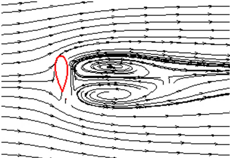
Schematic flow structures of marine current turbine with additional device are shown in Figure 11. According to the numerical result, two Karman vortices (vortex A and vortex B) are found behind the flange of the additional device. The main reason for forming vortex A is the low pressure area produced by additional device. Because of vortex A, the flow velocity around the rotor may be increased, which will push the hydrofoil work. However, the flange structure of additional device is the main reason to form vortex B.
5. Conclusion
The flow field of the marine current turbine with and without additional device is simulated numerically by the CFD software FLUENT. Numerical simulation results agree with experimental results, and the output power of the marine current turbine with additional device is higher than that of the original type, but the additional

Figure 10. Centric axial flow velocity in marine current turbine.

Figure 11. Schematic flow structures around marine current turbine.
device has an uneven force. There are two Karman vortices behind the flange of additional device. The low pressure region produced by additional device and flange structure can speed up the flow around the marine current turbine, so as to improve the output power. It has obvious effect for improving the output power of marine current turbine by designing reasonable additional device.
6. Acknowledgements
This investigation was supported by Natural Science Foundation of China granted No. 50735004 and Zhejiang Provincial Natural Science Foundation Granted No. R1100530.
REFERENCES
- Y. G. Lin, W. Li, H. W. Liu and S. Ma, “Ocean Current Power Generation Technology for Underwater Turbine,” Journal of Zhejiang University, Vol. 42, No. 7, 2008, pp. 1242-1246. doi:10.3785/j.issn.1008-973X.2008.07.029
- C. Z. Yang, H. C. Liu and Y. L. Zhou, “The Design of Horizontal Axis Wind Turbine Blades and the Analysis of Flow Field Based on CFD,” Journal of Northeast Dianli University, Vol. 30, No. 1, 2010, pp. 21-26.
- H. J. Yan, D. M. Hu and J. Li, “Numerical Simulation of Flow Field for Horizontal-Axis Wind Turbine Rotor,” Journal of Shanghai University of Electric Power, Vol. 26, No. 2, 2010, pp. 123-126.
- T. Chanin, B. Sarun and L. N. Sankar, “Numerical Simulation of the Aerodynamics of Horizontal Axis Wind Turbines under Yawed Flow Conditions,” Journal of Solar Energy Engineering, Vol. 127, No. 4, 2005, pp. 465-474. doi:10.1115/1.2035705
- Y. J. Ohya, T. Karasudani, A. Sakurai, K. Abe and M. Inoue, “Development of a Shrouded wind Turbine with a Flanged Diffuser,” Journal of Wind Engineering and Industrial Aerodynamics, Vol. 96, No. 5, 2008, pp. 524-539. doi:10.1016/j.jweia.2008.01.006
- S. Ma, W. Li, H. W. Liu and Y. G. Lin, “A 25KW Stand-Alone Horizontal Axis Tidal Current Turbine,” Automation of Electric Power Systems, Vol. 34, No. 14, 2010, pp. 18-22.
- D. H. Zhang, W. Li, Y. G. Lin, Y. Ying and C. J. Yang, “Simulation of Generation System of Marine Current Turbine with Pressure-Maintaining Storage Based on Hydraulic Transmission,” Automation of Electric Power Systems, Vol. 33, No. 7, 2009, pp. 70-74.