Journal of Modern Physics
Vol. 2 No. 8 (2011) , Article ID: 7121 , 13 pages DOI:10.4236/jmp.2011.28105
Model of Preformed Hole-Pairs in Cuprate Superconductors
Physics Department, Aligarh Muslim University, Aligarh, India
E-mail: ranajsingh@yahoo.com
Received Febrary 4, 2011; revised March 29, 2011; accepted April 15, 2011
Keywords: High Temperature Superconductor, Electron Paramagnetic Resonance, Preformed Hole-Pairs
ABSTRACT
A model of preformed hole-pairs in cuprate superconductors has been proposed based on some experimental results i.e., 1) electron paramagnetic resonance spectra of quenched superconductors which show very frequently the fragment (CuO)4 broken off from the CuO2 layer in the structure, 2) 41 meV peak observed in neutron diffraction and nuclear magnetic resonance spectra of superconductors, 3) Heisenberg exchange interaction leading to ferromagnetism observed in CuO which is an essential ingredient of all superconductors and some generally accepted conclusions i.e., a) that the order parameter in superconductors has  symmetry and b) coherence length is of the order of 15 - 20 Angstrom. Heisenberg exchange interaction between two (CuO4) plaquettes each containing a lattice hole binds the two holes which are the charge carriers in the cuprate superconductors. It is not very clear whether the hole-pair is in the triplet or singlet state, but the triplet state is supported by the experimental observation of ferromagnetism in the parent material CuO. The proposed hole-pair singlet is different from Zhang-Rice singlet.
1. Introduction
Various mechanisms have been proposed for high temperature superconductivity (HTS), but as yet no consensus has been reached. People have started thinking away from Cooper pairs in BCS theory. New thinking is that hole-pairs are formed even before the transition temperature (Tc) and they condense at Tc. The mechanism of formation of hole-pairs is expected to be quite different from that of Cooper pairs. A model of hole-pairs in cuprate superconductors has already appeared in the reference [1]. But the present model is entirely different. In the reference [1], the pairing between two holes has been shown to be due to the existence of medium of negative dielectric constant between the two holes. In the present model, pairing between two holes has been shown to be due to “exchange interaction” between the two holes. Several mechanisms have been proposed for HTS, but there is no consensus on any mechanism. This led the author to propose yet another mechanism of HTS. Out of the many mechanisms proposed, one will stand out and get universal acceptance. The paper in the reference [1] and the present paper are based on the same set of experiments carried over many years. There is bound to be some overlap in the description of the experimental data. But the hearts of the solutions of the problem of HTS are totally different.
The basic idea of this model has been derived from some experimental results as 1) electron paramagnetic resonance (EPR) spectra of quenched superconductors which very frequently show (CuO)4 fragments broken off from the active CuO2 layer in the cuprates, 2) 41 meV peak observed in neutron diffraction and nuclear magnetic resonance (NMR) spectra of superconductors and 3) Heisenberg exchange interaction leading to ferromagnetism (FM) in CuO in nanoforms, sometimes even up to room temperature (RT) and some generally accepted conclusions as a) that the order-parameter of cuprates has  symmetry and b) that the coherence length is of the order of 15 - 20 Angstrom (A).
HTS are EPR silent because Cu2+ ions are coupled antiferromagnetically. When cuprates are quenched or deoxygenated, some oxygen ions are ejected from the crystal or are displaced from their usual positions, producing small fragments magnetically isolated from the bulk, such as Cu-tetramers and also monomers, dimers and octamers which have been detected by EPR. Besides Cu-monomer (Cu2+ or CuO), Cutetramer (CuO)4 is the most frequently occurring species which is probably due to the fact that (CuO)4 is the unit cell of the twodimensional CuO2 sheet in the HTS compounds and also in the constituents of superconductors as BaCuO2, CaCuO2, SrCuO2, Bi2CuO4 etc. When HTS materials are heated up to temperatures a little higher than the temperatures of their preparations and then suddenly quenched, the CuO2 sheet is most likely to be broken into pieces containing unit cells of the sheet. In this process, many (CuO)4 units may be further broken giving Cu-monomers. The frequent occurrence of (CuO)4 spectra seems to have special bearing with the mechanism of superconductivity in cuprates.
In the Figure 1(a) is shown a fully connected (CuO)4 plaquettes and in Figure 1 (1(b)) an isolated (CuO)4 plaquette whose all the oxygen bonds with Cu2+ neighbours have been broken . In the reference [2], it has been shown that the Cu-O bond in HTS is nearly 87.5 % ionic and 12.5% covalent. If eight neighbouring bonds are broken, it means loss of one electron (12.5 × 8 = 100%) or advent of one hole in the remaining (CuO)4 unit because oxygen is more electronegative than copper. It suggests that if a hole enters the (CuO)4 unit of continuous CuO2 sheet, it becomes equivalent to an isolated (CuO)4 entity and should have the same properties as an isolated (CuO)4 entity which are obtained on quenching of HTS materials.
We have studied EPR spectra of nearly all cuprate superconductors [3-10] and their constituents as BaCuO2, CaCuO2, SrCuO2, BiCuO4 etc. after quenching and in each case obtained and analyzed the spectra of (CuO)4 and also other fragments. Similar spectra in cuprates have been obtained by other workers [11-16] also though sometimes with different interpretations.
In the EPR spectra of isolated (CuO)4 entities, four fine structure components were observed showing that
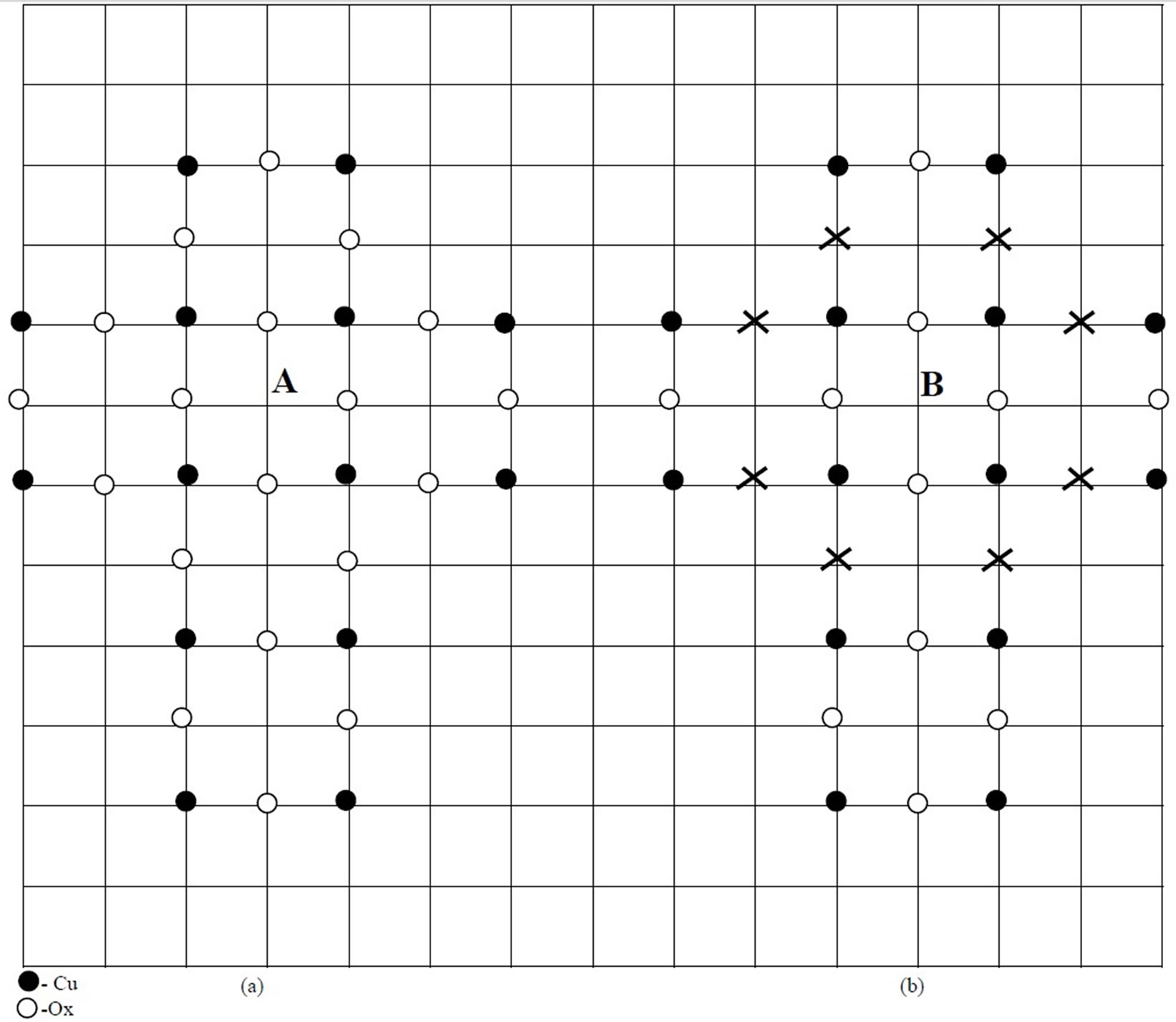
Figure 1. (a) An unit cell of CuO2 plane connected on all sides. (b) An unit cell of CuO2 plane whose eight neighbouring bonds have been broken by removal of eight oxygen ions (shown by crosses).
the total electronic spin = 2, obtained due to FM coupling of the four spins of four Cu2+ ions of (CuO)4 (electronic spin of Cu2+ = 1/2) and in some cases, each fine structure component showed further splitting into thirteen hyperfine components , showing the FM coupling of nuclear spins of all the four Cu2+ ions giving total nuclear spin = 6 (nuclear spin of Cu = 3/2). Fine structure splitting will take place due to crystal field effects of the surrounding ions on the isolated Cu-tetramers. Coupling of nuclear spins will be possible if all the four holes of the four Cu2+ ions circulate around the (CuO)4 framework with a frequency larger than 1/γHhfs where γ = gyromagnetic ratio and Hhfs = hyperfine splitting. The expected path of circulation of holes has been shown in the Figure 2(a). The circulation of the four holes of the four Cu2+ ions around the periphery of (CuO)4 framework (Figure 2(a)) will be due to the advent of a hole wandering in the CuO2 sheet in a (CuO)4 plaquette which will hop among its oxygen sites. Hopping of the hole among the different oxygen sites will force the holes of Cu2+ ions also to move and circulate in the (CuO)4 framework due to electric repulsion between the incoming hole and the Cu2+ holes. Electronic spins of the four holes of the four Cu2+ ions in the isolated (CuO)4 units order themselves in FM arrangement because the incoming hole hopping among oxygen sites places them in identical conditions and identical situation will be obtained when their spins are aligned in the same direction or are FM ordered. FM ordering of electronic spins of all the four Cu2+ holes and their identical motion in the (CuO)4 framework will create identical situation for the nuclear spins of the four Cu-nuclei and hence they will also be pointing in the same direction. Thus electronic spins and also nuclear spins of the four Cu2+ ions will be FM aligned.
From above we can expect near equivalence between an isolated (CuO)4 and a (CuO)4 unit in a continuous CuO2 layer in which a hole has entered or the following equation may hold good: an isolated (CuO)4 plaquette = a (CuO)4 plaquette of the continuous CuO2 sheet + a hole inside it.
Based on this equivalence and some experimental results and some generally accepted conclusions enumerated earlier, a model of preformed hole-pairs in cuprate superconductors has been proposed.
The main difference in the situations when a hole enters an isolated (CuO)4 unit and a (CuO)4 unit in a continuous CuO2 sheet is the following. In the case of isolated (CuO)4 unit , all kinds of motion of holes and spin alignments are confined to itself because there is practically no connection with the outside world. In the case of

Figure 2. (a) Dotted lines show the path of circulation of the four holes of four Cu2+ ions of a (CuO)4 plaquette, (b) When all the spins are aligned vertically above the CuO2 plane, then Ms = 2 and the state is denoted by the symbol U; coming back to the plane when spin vectors are in CuO2 plane i.e., Ms = 0, the sate is called Uo; again spins aligning vertically below the plane, Ms = –2 and the state is called D; again reversing direction and coming back to the plane,. Ms = 0 and the state is called Do. Resultant spin vector changes angle by 90˚ in the consecutive states U, Uo, D, Do and then U again.
a hole entering the (CuO)4 unit of a continuous CuO2 sheet; as soon as a hole arrives in a (CuO)4 area, the spins start arranging themselves in FM alignment and at the same time they start a train of AFM coupling with the neighbouring spins because HTS are basically doped antiferromagnets. A train of AFM coupling may give rise to the formation of spin stripes. When hole-pairs are formed, the AFM coupling with the outside spins will not take place. Because the two holes are bound by exchange forces and remain confined in the d x2–y2 orbital.
Before proposing the model, let us examine what happens in a (CuO)4 unit in the continuous CuO2 sheet when a hole lands into its area. Because of its equivalence with the isolated (CuO)4 unit, as soon as a hole enters a (CuO)4 unit, the spins of the holes of all the four Cu2+ ions would be set up in the process of FM alignment. But the question is what will be the direction of spin alignment? The unbiased or preferential direction will be perpendicular to the CuO2 plane. If the alignment is vertically upward of the plane, there is equal probability of vertically downward direction. As a compromise, the aligned spins will oscillate between these two directions. But with what frequency? We associate this frequency with 41 meV peak [17]. 41 meV when expressed in the form of hν, ν comes to be approximately equal to 1013 hertz or its time-period ≈10–13 sec. So the frequency of oscillation of spin vector ≈1013 hertz. Indirect support for the alignment of spin vector in a direction perpendicular to CuO2 plane comes from the reference [18] in which it has been shown that modest magnetic fields suppress the resonance in the magnetic excitation spectrum of YBa2Cu3O6+x significantly when perpendicular to CuO2 plane than for parallel fields. When a hole marches through a column or row of (CuO)4 plaquettes, the process of phase alignment of spin vectors of the four holes of the four Cu2+ ions in (CuO)4 units follows it. In the cell which we call first, let us assume that the spins have arranged themselves in the U state(i.e., all spin vectors pointing vertically upward) and as the hole advances, a sequence of well defined spin aligned states U (Ms = 2), Uo (Ms = 0), D (Ms = –2), Do (Ms = 0) is obtained. These symbols U, Uo etc. have been explained in the caption of the Figure 2(b). Ms represents the combined projection of the four spins of the four Cu2+ ions in a (CuO)4 plaquette on Z-axis which is perpendicular to CuO2 plane i.e., XY plane. These well defined states will not be obtained in consecutive (CuO)4 units. This sequence of well defined spin states will be found in (CuO)4 units at fixed distances between them. The journey of the hole through one round of these well defined spin states is completed when it traverses a length of ten (CuO)4 units as shown in the Figure (3). It means that the successive well defined spin states will come after the hole crosses two and a half plaquettes [see Figure (3)]. It also means that a hole will take 10–14sec. to cross a plaquette because ten (CuO)4 units are crossed in 10–13sec which is the time period of spin oscillation.
Another important thing that will happen to (CuO)4 entity is that all the four Cu2+ holes have to circulate around the outer boundary of (CuO)4 [see Figure 2(a)]. Circulation of Cu2+ holes around the boundary of (CuO)4 plaquette is a necessity if coupling of nuclear spins of four copper ions has to be materialized whose signature is provided by EPR spectra. But here again the question is with what frequency? Cu2+ holes will circulate around the boundary of (CuO)4 plaquette? For this let us calculate the thermal velocity of holes (mass of hole = mass of electron = m = 9.11 × 10⁻²⁸ gm.) at the temperature of 92 K = Tc of the workhorse YBa2Cu3O7–δ. In the twodimensional plane , thermal energy =  KT, because thermal energy per degree of freedom =1/2 KT. Putting numerical values, thermal energy = KT = 1.38 × 10–16 × 92 = ½ mv2 = (kinetic energy of hole). Thus velocity of hole v = 5.28 × 106 cm/sec = 5.28 × 10¹⁴ A/sec. The next question is what will be the perimeter of the path through which Cu2+ holes will circulate. It will not be simply 3.84x4 A, as the side of the square (CuO)4 unit = 3.84 A [3.84 A is one side of the unit cell of the YBa2Cu3O7–δ; the unit cell has been taken as a square]. If so, holes have to pass through the interior of the nucleus which is certainly not possible. They must maintain the same distance from the Cu nuclei as the outermost electron will maintain. According to Bohr theory (taking the reported value of effective Z of Cu = 13.2), the radius of Cu-3d orbit has been calculated to be 0.3615A. So circulating along the path ABCDA shown in the Figure 2(a), the holes will keep away from the Cu-nuclei by this distance and circulate along the outer boundary. So the total path length = 4 [3.84 + 2 (0.3615)] = 18.252 A. and frequency of circulation of holes = (5.28 × 10¹⁴/18.252) ≈ 2.9 × 10¹³ hertz or time-period = 0.345 × 10⁻¹³sec.
We are assuming the velocities of the both the holes wandering in the CuO2 plane and the holes of Cu2+ to be equal i.e., 5.28 × 10¹⁴ A/sec. It may not sound very reasonable. One hole is wandering nearly free on the CuO2 sheet and the other is associated with Cu2+ ion. But the Cu2+ holes while circulating on the outer boundary of (CuO)4 plaquette may be treated as free as the wandering hole. On this argument, the velocities of the both kinds of holes has been taken to be equal.
As we have mentioned earlier, in accordance with the occurrence of the 41 meV peak [17] that the wandering hole spends 10–14sec in one (CuO)4 plaquette and the Cu2+ hole circulating on the boundary of the (CuO)4 unit should also be circulating for the same time when the

Figure 3. Formation of hole-pairs. All the squares A.B.C.D.E.F.G.H.I are the unit cells of the two-dimensional CuO2 plane. Both the holes traverse the same path but at any instant they are on the opposite sides of the central cell.
wandering hole is within the bounds of (CuO)4 unit. We have already assumed that the circulatory motion of Cu2+ is induced by the advent of the wandering hole in its area and it persists as long as the wandering hole is within its boundaries. In 10–14sec, the wandering hole can enter a plaquette, say, at position 1,then jump to position 2 and then exit the plaquette from the position 3 (see the Figure 2(a)). In the same time of 10–14 sec, each Cu2+ hole can cover one and a half time the length of a side of the square.
In this kind of circulatory motion, two things are noted, 1) spin magnets are getting closer and farther from the center of the square path ABCDA [see the Figure 2(a)] and 2) charged particles are moving in a closed path. None of the Cu2+ holes completes one round of the path ABCDA, but if these holes are considered indistinguishable, the closed path has been traversed one and a half time by a hole. Under this condition, magnetic fields should be created by both the causes mentioned just above.
Let us calculate magnetic fields due to both causes. Due to the first cause, the magnetic field produced at the center of the circulatory path = 4 μ/r3 (where μ = Bohr magneton = magnetic moment associated with the spin momentum of one electron/hole and r = distance of magnetic moments from the center of the path ABCDA at which magnetic field is being estimated. If all the spin vectors are in phase and pointing vertically upward of the CuO2 plane , each one occupying one corner of the path (see the Figure 2(a)), the magnetic field at the center of the path = 1853 gauss. If they are situated at the middle points of the sides of the square path, then the magnetic field = 5241 gauss. But the field direction is changing so fast that (time-period = 10–13 sec) that the time average value of the magnetic field will be zero. Only on the time-scale of less than 10–13 sec, finite value of magnetic field may be observed. The magnetic field produced by the second cause has been calculated to be 72 gauss (by the standard method that field = μ0/2 × I/r, if r is taken as the radius of the circle whose circumference has been taken to be equal to the perimeter of the path ABCDA =18.252 A).
Hsu et al. [19] argued that due to circulatory current in the CuO2 plane, a real magnetic field should be produced which they tested by muon spin resonance and neutron scattering but were unable to detect any field probably due to fast temporal and spatial change of magnetic field .The magnetic field is of transient nature and its estimation is quite difficult but in the present case where the time scales are of the order of 10–13 sec, the presence of magnetic field can be experienced by the system.
So far we have shown that when the wandering hole enters a (CuO)4 plaquette it experiences a magnetic field generated by the spin magnetic moments of the holes associated with the Cu2+ ions and their circulation around the boundary of (CuO)4 plaquette. We will see further that this magnetic field will guide the motion of the wandering hole in the network of (CuO)4 plaquettes in the CuO2 plane. Next we try to show how the two wandering holes form hole-pairs by virtue of Heisenberg exchange interaction.
2. Formation of Hole-Pairs
Before discussing formation of hole-pairs, let us be clear about the two kinds of holes of different origins which have entered our discussion. One kind of holes are the set of four holes, each one associated with one of the four Cu2+ (3d9) ions which circulate about the periphery of (CuO)4 framework as discussed earlier. These holes will be called Cu2+ holes. The other kind of holes are those which are always present in the superconductors. In cuprate superconductors, doping is believed to create holes on the oxygen sites in the CuO2 layer. They wander in the CuO2 plane with thermal velocity. They will be called lattice holes.
In analogy with the reference [20], the binding between two holes seems to be through the Heisenberg exchange interaction because conditions of binding in the two cases are quite similar. There are a large number of lattice holes wandering in the two-dimensional CuO2 plane When two holes traveling in the opposite directions in the same column or row .of the CuO2 continuous sheet come at a distance of nearly four (CuO)4 units as shown in the Figure (3) they might feel a mutual force of attraction due to Heisenberg exchange interaction The separation of four (CuO)4 units has been chosen because the coherence length is known to be 15 - 20 A or nearly equal to the length of four (CuO)4 plaquettes kept side by side.
In the reference [20], the strength of Heisenberg exchange interaction for a series of small free radicals in aqueous solution has been measured. In this case, the critical exchange distance lies between one and three times the hard sphere encounter distance. The situation we are imagining in the cuprate superconductors appears to be similar to that of free radicals noted above due to the following similarities; 1) when a lattice hole enters a neutral (CuO)4 unit, it may behave like a free radical., 2) two (CuO)4 plaquettes each with a hole in it are situated three (CuO)4 blocks away [we have taken two (CuO)4 plaquettes each with a hole in it at a distance of three plaquettes in agreement with coherence length], 3) in between the Cu2+ plaquettes each containing a hole the space is neutral (plaquettes without holes) as between radicals in aqueous solution. Thus there is enough probability of exchange interaction between the two (CuO)4 plaquettes, each containing one hole. When the two holes proceed further, there will be a separation of only one block, then also the exchange interaction should continue as the radicals in the aqueous solution. Still further when the two holes will enter the same (CuO)4 plaquette, the exchange interaction should not occur as happens in the present case. In the case of free radicals in aqueous solution also, exchange interaction does not take place at a distance less than one hard sphere encounter distance.
Let two lattice holes reach A and E cells three blocks apart simultaneously. At this separation they will experience exchange force. There are chances of two kinds of interactions: a) spins of Cu2+ holes both in A and E cells are ferromagnetically coupled and b) they are antiferromagnetically coupled. Discussion of both cases (a) and (b) are on similar lines. In the FM coupling, if the Cu2+ holes in the A cell are in U state, the spins of the Cu2+ holes in the cell E will spontaneously attain the U state under the effect of exchange interaction whatever may be their initial configuration. In the case of AFM coupling, the spins of Cu2+ holes in A and E cells will be in U and D states respectively under the effect of exchange interaction. It may be mentioned here that the spins of Cu2+ holes and spins of lattice holes do not compound together, because there is no evidence of compounding of these two kinds of holes in EPR spectra of HTS or their constituents. So the motion of lattice holes are governed by the magnetic field produced by the Cu2+ holes of the cells in which they are situated at a particular instant. For the sake of clarity, only case (a) of FM coupling will be discussed at length and case (b) will be taken at the end and its main result will be discussed.
We first discuss the case (a) of FM coupling. The lattice holes from both the cells A and E will proceed towards each other with thermal velocity. But as mentioned earlier, when they proceed along the cells, the spin configurations of Cu2+ holes will go on changing from U state towards U0 state and so on Now let us estimate the exchange interaction energy between the Cu2+ ions of the plaquettes in A and E.cells. There are several theoretical methods of calculating exchange energy. They are quite involved and do not always give satisfactory results. There are also empirical values of exchange interaction which are obtained by specific heat data. But in the present problem, we are interested in the properties of only the CuO2 plane in the cuprate superconductors and not the whole superconductor for which there may not be any specific data. For calculating Heisenberg exchange integral J, we use the standard formula [21]
 (1)
(1)
assuming that Tc is the transition temperature of the superconductor under consideration at which the ferromagnetic coupling of holes vanishes and consequently superconductivity also vanishes. In (1), k = Boltzmann constat =1.38 × 10⁻¹⁶ ergs, Tc is the transition temperature of the YBa2Cu3O7–δ, = 92 K, z = number of nearest neighbours of Cu2+ ion = 4, s = spin = 1/2. Here z = 4 because every Cu2+ ion in the cell A has 4 Cu2+ nearest neighbours lying in the cell E and vice versa. Putting numerical values in (1), J = 3.9675 meV. The exchange interaction Eex also has been calculated by the standard formula
 (2)
(2)
Putting numerical values in (2), Eex = –7.935 meV. This exchange interaction energy Eex is also the exchange interaction energy between two lattice holes, one in the cell A and other in the cell E , because lattice holes and Cu2+ holes in the respective cells are inextricably connected. However, exchange interaction energy between two lattice holes in A and E cells calculated by the formulae (1) and (2) gives the same values which are as follows:  =15.87 meV (with z = 1) and
  = –7.935 meV(with i = j = 1). Thus the two lattice holes are bound by Heisenberg exchange energy and may form a hole-pair which are charge carrier in the superconductors. This hole-pair is different from Zhang-Rice pair which is a singlet, but the present one is a triplet. Zhang-Rice singlet [22] is formed between a lattice hole and a Cu2 hole. The present hole-pair is formed between two lattice holes.
Better statistical approximations show that for different crystal structures, J can be increased by a factor more than one. For SC, BCC, ECC this factor is 0.5/0.28, 0.5/0.325, 0.5/0.346 respectively. In the present case, the system under consideration is two-dimensional CuO2 crystal and the factor is not known by which J or Eex should be multiplied. If Eex is multiplied by the average of these factors = 1.59, it becomes equal to 12.6 meV. We are not sure about the multiplying factor but it is certain that Eex must be greater than the calculated value of 7.935 meV or anywhere between 7.935 and 12.6 meV which in terms of temperature is equivalent of 95 K to 151 K which covers nearly the whole range of Tc’s of cuprates.
In the case of the two lattice holes one in each of A and E cells, the spin directions are vertically upward of the CuO2 plane and the separation is three blocks of (CuO)4. There will be strong exchange interaction. But in a very short time (≈10–14 sec), the hole from the A-side will cross over to B-cell and that from E-side to D-cell [Figure (3)]. After they have entered the new cells, there will be rephasing of the spins of the Cu2+ in the B and D-cells. The spin vectors of Cu2+ holes in B and D-cells will be tilted from the vertical direction by an angle ωt (ω = angular velocity of spin oscillation and t = time elapsed for the lattice hole to come to the new cells B and D from A and E respectively). Change of angle by ωt may be understood from the Figure 2(b). It means that the vertical component of spin vectors of each of the Cu2+ holes has decreased by a factor  and a horizontal component of the spin vectors of each of the Cu2+ holes will be equal to the magnitude of the original vertical component multiplied by
  The spin vectors of Cu2+ ions of B and D cells will remain parallel to each other though inclined to the vertical direction and the separation between the two cells will be at least the length of one (CuO)4 plaquette. In this case also the exchange interaction will be continued but with less vigour than that between A and E cells because of the trend shown by the exchange interaction to reduce when the separation is further reduced. As they proceed further, both of the lattice holes enter the cell C , where the vertical component of spin vectors become negligibly small and finally at or near the center of the cell , they become zero and so also the horizontal component. Moreover, both the lattice holes are enclosed in the same cell and very close to each other and hence there is no probability of exchange interaction taking place. More about the motion and behaviour of the two lattice holes enclosed in the same cell will be discussed in detail in the next section.
3. OrderParameter of the Hole-Pair
We will show now. how the magnetic field produced by the spin moments of Cu2+ holes in different (CuO)4 units control the motion of lattice holes and how  order parameter is obtained. We describe the motion of the two holes mathematically and show that their path resembles the
  orbitals of electrons in atoms.
In the Figure (3), the squares A,B,C,D,E,F,G,H,I are the unit cells of the two-dimensional CuO2 lattice, each cell being a square of side = 3.84 A which is approximately equal to the size of (CuO)4 plaquette or unit cell of the twodimensional CuO2 plane in Y-123 superconductor. When two holes enter the Figure 3 from opposite sides, one from the A side and the other from the E side, they feel an attractive force due to exchange interaction between them and continue moving towards each other with thermal velocity. Because they are charged particles, their motion will be guided by the magnetic field produced by the Cu2+ holes of the (CuO)4 plaquettes in which they are situated at any instant. The motion of a hole is confined to XY plane and its velocity can have only two components Vx and Vy. The velocity of a charged particle does not change by magnetic field; only its direction is changed and V2 is always equal to Vx2 + Vy2. Motion of a charged particle of charge = e in XY plane under the action of the magnetic field Hz (in the Z-direction) is given by the following equations.
 (3)
(3)
 (4)
(4)
 (5)
(5)
where m is the mass of the charged particle. The Equation (5) goes to zero and need not be considered further.
Before proceeding further we will clarify some symbols and their different forms in which they are used here. They are 1) angular velocities ω and ω’, 2) Vx and Vy to be used in the form of ( ) and (–
 ) respectively and 3) Hz to be used as
 .
.
1) Under the effect of exchange interaction and magnetic field generated by the Cu2+ holes and its own thermal velocity a lattice hole (numbered 1) starting from A-cell goes to C, then to I, back to C, then to E. In the meantime, the spins of the Cu2+ holes start from U-state at A goes to Uo at C, then to D at I, then to Do at C and to U again at E. We see from the Figure (3) that the geometrical angle from A to E is 180˚, but the spins of the Cu2+complete 360˚ in going from U to U state. To differentiate between the two, the spin angles will be denoted by ω and the geometrical angle by ω’. Obviously ω’ = 2 ω. It is to be noted that ω’ is the angular frequency of rotation of a charged particle with charge = e and mass = m in XY plane with the magnetic field in the Z-direction and it is equal to eHz/mc (where c = velocity of light).
2) A lattice hole arrives at A with thermal velocity V and moves forward under the effect of magnetic fields generated by Cu2+ holes. Velocity V has now two components Vx and Vy. In the Figure (3), X-axis is from the origin O (center of the cell C) towards I and Y-axis is from O towards A. The components of velocity V are
 (6)
(6)
(-ve sign is because the hole is proceeding opposite to the positive Y-axis;  is used because Vx and Vy depends on the inclination of the spin vectors from the vertical direction expressed by the angle ωt). and
 (7)
(7)
3) In (3) and (4), Hz represents the vertical magnetic field. If (3) and (4) are to be used to describe the motion of holes, the vertical magnetic field should be expressed as , because Cu2+ spin vectors leans away from the vertical direction as they move from A with angular velocity ω and the vertical component of magnetic field decreases as
 .). The vertical magnetic field both in A or E cells are equal to Hz because, here ωt = 0 in the general expression of magnetic field Hz Cos ωt. In the light of above clarifications, (3) and (4) can be written as
 (8)
(8)
 (9)
(9)
Vx in (7) and Vy in (6) can be written with the help of (a ) part above as
 (10)
(10)
 (11)
(11)
Differentiating (10) and (11) with respect to t, we get
 (12)
(12)
 (13)
(13)
Equating dVx/dt and dYy/dt from (12) and (13) with those of (8) and (9) respectively, we have
 (14)
(14)
 (15)
(15)
From (14),

 (16)
(16)
And from (15),

 (17)
(17)
 , and substituting Vx and Vy from (16) and (17), we have
 (18)
(18)
We have mentioned earlier that eHz /mc = ω’, so (18) can be written as
 (19)
(19)
Further discussion of the problem has to be done in terms of spin angles ω, so (19) in terms of ω becomes
 (20)
(20)
Until now, all the above eqns are associated with the velocities of particles (holes) and to convert them to actual coordinates, both sides of (20) are integrated, which gives
Because the integral
 (21)
(21)
 (21’)
(21’)
where R is some length used for plotting Equation (21’).
(21’) can be plotted in a special way Left t hand side (LHS) of (21’) will describe a circle with radius = R when t is changed from 0 to T to 2T, where T is the time period of the rotation of spin vectors of Cu2+ holes. R has been given a nominal value of 7.68 A which is twice the side (3.84 A) of the unit cell of the CuO2 plane of Y-123 superconductor. The right hand side (RHS) including the term R/2 (=3.84 A) will indicate the position of the lattice hole at an angle ωt. The magnitude of RHS of (21’) is shown by a straight line from the position of the angle ωt on the circumference of the circle towards the center of the circle. The tip of the line (shown by dots) represents the position of the lattice hole. The values of RHS of (21’) have been shown in the Table 1. The positions of the lattice holes at different spin angles (ωt) have been shown in the Figure (3). In Table 1, in the range of spin angles 180˚ - 360˚ and 540˚ - 720˚, the values of RHS of
(21’) comes to be negative. But they have to be plotted in the same way as those values which are positive. It is due to the fact that at all ωt values, the holes are directed towards the center of the figure by exchange forces.

Table 1. ωt = angle which the spin vector of the hole makes with a direction perpendicular to the CuO2 plane . In the rotation of 360˚ in the Cartesian system, the spin vector completes two oscillations and so ωt varies from 0˚ - 720˚. The expression 3.84. │ gives the position of the hole at the angle ωt in the Figure (3).
Moreover, the ± sign in (21’) can make all the quantities positive as required. So it is better to write (21) or (21’) in the following form.
 (22)
(22)
Till now, we have mainly discussed the motion of the hole1. The conditions governing the motion of the hole 2 is identical to that of the hole1 and they execute the same kind of motion, only difference being that the hole 1 starts from the A-cell and the hole 2 starts from the E-cell at the same time, Both the holes repeatedly traverse the four lobes in the Figure 3 in the same time but are always situated diametrically opposite to each other. In the Figure 3 we see that the path of the pair of lattice holes (1 and 2) has four lobes around the center which is like the orbitals of electrons in  configuration. We started with the pre-knowledge that the symmetry of the hole-pair is
  type and developed a model which corroborates it, demonstrates the correctness of our logic.
On examining the Figure 3, two important questions arise, 1) why the hole 1 coming from A on reaching C is deflected towards I-cell and the hole 2 towards the F-cell and 2) why the two holes on reaching extreme ends of the figure bounce back. To answer these questions, we will examine the Figure 3 and the Table 1 in detail. At 62˚, the position of the hole 1 is just at the upper boundary of the cell C. From 62˚ to 74.6˚, the position of this hole is inside the cell. At 74.6˚ its position is just at the center of the cell C or at the middle of the diagonal PQ in the cell C. Beyond 74.6˚ it crosses the diagonal PQ through the center. Between 74.6˚ and 105.4˚ the position of the hole is beyond the diagonal PQ. Near 90˚, the positions of the hole is beyond the premises of the cell. Specially at 90˚, the hole seems to go to infinity (see the table 1). At 118˚, the position of the hole is at the RHS boundary of the cell C. At 180˚ the position of the hole is at the extreme right at the center of the cell I. On reaching 180˚, it turns back and the path between 180˚ and 3600 is of similar nature to that between 0˚ and 180˚ but in different quadrant of the circle (see Figure 3).
Now we consider the motion of the hole 2 which starts its journey from 360˚ where as the hole 1 had started its journey from 0˚ The position of the hole 2 at an angle (360 + θ)˚ is equivalent to the position of the hole 1 at an angle θ, but always in opposite quadrants. For example, the position of the hole 2 from 360˚ to 540˚ lying in the third quadrant is just opposite to that of the hole 1from 0˚ to 180˚ lying in the first quadrant of the circle. Near 450˚ the position of the hole 2 is beyond the diagonal PQ towards the first quadrant. At 450˚ it seems to go to infinity. At 540˚ the hole 2 is at the left extreme in the cell F. On reaching 540˚ the hole 2 turns back and the path between 540˚ and 720˚ is of similar nature to that between 360˚ to 540˚ but in the fourth quadrant. As time advances, both the holes navigate the full circle but always remaining opposite to each other. Both of them bounce back when they reach the four extreme positions shown in the Figure 3.
When the holes 1 and 2 enter simultaneously the cell C there is practically no magnetic field generated by the Cu2+holes to guide their motion because in the cell C, the spins of the Cu2+ holes are in the  state or very near it where no magnetic field is generated by the Cu2 holes (see Figure 2(b)). At such close separation there is no probability of exchange interaction to exist. When exchange interaction takes place between two electrons or two holes, the dominant interaction between them is attractive interaction and the usual electric and magnetic effects become negligible. When two holes or electrons come very close to each other in the absence of exchange interaction, the electric and magnetic effects become prominent but the former substantially outweighs the latter. So in the absence of exchange interaction, the trajectory will be decided by the electric repulsion between the two holes particularly when both lie in the cell C.
The entry points for the holes1 and 2 in the cell C are at the angles 62˚ and 422˚ respectively. As the angles ωt exceeds 62˚ and 422˚ for holes 1 and 2 respectively, they come closer inside the cell C where there is no exchange interaction effect, they will repel and push back each other from their calculated positions. As the angle ωt increases from 62˚ to 90˚ for the hole 1 and from 422˚ to 450˚ for the hole 2, the separation becomes less and less, repulsion stronger and stronger and mutual pushing back more and more.
At 90˚ for the hole1and 450˚ for the hole 2, they experience maximum repulsion and so maximum push back from their expected positions which are at the center of the cell C. Beyond 90˚ for the hole 1 and beyond 450˚ for the hole 2 ,repulsion gradually decreases and the push back is less. From 90˚ to 118˚, the hole 1 experiences the same kind of repulsion and push back as from 90˚ to 62˚. The hole 1 takes the path MTN [see Figure 3] and at 118˚ enters the cell H on the right hand side. Similarly the hole 2 takes the path KLJ from 422˚ to 478˚ and enters the cell G on the left hand side. Thus both the holes change their routes after entering the cell C The hole 1 will cross the cell H with its thermal velocity modified by the magnetic field produced by Cu2+ holes in that cell. After the cell H, the hole 1 will enter the area of the cell I. At the same time and by similar process the hole 2 will enter the area of the cell F. There is stronger strength of exchange interaction when one hole is in the F-cell and the other in the I-cell than that when they were in the G and H-cells. After reaching the extreme ends, both the holes will bounce back and return to the C-cell again and deflected left and right as they had on entering this cell earlier. Thus they will continue traversing the orbital of  symmetry.
But the question is why the holes 1 and 2 bounce back from their extreme positions in I and F-cells respectively and why not continue their forward journey beyond I and F. As calculated by (2), the exchange interaction energy is greater than 7.935 meV and may go up to 12.6 meV.
The maximum kinetic energy a hole can have = 
where m = mass of the hole taken to be the mass of an electron and v = velocity of hole = 5.28 × 106 cm./sec. Thus kinetic energy = 7.937 meV. The holes on reaching the extreme points, each one has kinetic energy = 7.937 meV and the attractive exchange energy between them lying somewhere between 7.935 and 12.6 meV. Thus the attractive energy exceeds the kinetic energy and will pull the holes back from the extreme positions i.e., there will be a mirror action at the extremities. Thus the two holes will remain confined to the  shaped space. It is also obvious that the two holes spend more time in the cell C than an equal path in any other region because of the reduction of their velocities due to repulsion between them. In all the quadrants they traverse a parabolic path like MTN with reduced speed and spend much time around the center. It indicates that in
  symmetry of the order parameter, there may be slight admixture of s-wave character also as suggested by many workers.
Exchange energy has been assumed and its strength calculated in the CuO2 layer of Y-123 superconductor (using the data of transition temperature and unit cell dimensions). CuO2 is the active layer and common to all the cuprate superconductors. So the mechanism proposed here may be applied to all the cuprates. There is also experimental evidence of the existence of Heisenberg exchange interaction in the CuO2 layer of CuO which is the parent compound of all the cuprates. Ferromagnetism [23,24] in CuO has been observed and explained on the basis of exchange interaction.
Now we discuss the case (b). When two holes proceeding from opposite sides come at a distance of three (CuO)4 plaquettes in between them, there is equal probability that they will couple in FM or AFM order. In FM coupling, Cu2+ spin directions both in A and E cells initially will be along (+z or upward of the CuO2 plane ) direction , but in AFM coupling, initially the spin direction in A will be along (+z) direction and in E along the (–z) direction. But the trajectory of the two holes in both the cases will remain the same as shown in the Figure 3. This is due to the direction of force exerted by magnetic field on a conductor carrying current due to hole (+ charge). But in the case of AFM coupling , the two holes will be paired in singlet state But this singlet state will be different from that of Zhang-Rice [22]. Zhang-Rice singlet is due to the AFM combination of a Cu2+ hole and a lattice hole. The present singlet is due to the AFM combination of two lattice holes. In FM coupling 92 K (Tc of 123-superconductor) has been taken as Curie temperature. In AFM coupling, 92 K has been considered as Neel temperature In FM coupling, triplet will be the ground state (state of lowest energy) , but in AFM coupling, singlet will be ground state. It is difficult to choose which one will be the ground state, triplet or singlet. Going with the experimental evidence [23,24] that ferromagnetism is observed in CuO, there seems to be more likelihood of the coupling of two lattice holes in the triplet state.
When we say that preformed hole-pairs may provide a valid mechanism of HTS, a question arises as to what causes difference in the Tc’s of different superconductors. Probably it is the influence mostly of nearest layers of the CuO2 layer e.g., BaO in Y-123, CaO in Bi-, BaO in Hg-based superconductors etc that brings about the difference. Different neighbouring layers may change the chemical properties of CuO2 layer which probably decides the strength of hole-pair binding.
We have calculated the Heisenberg exchange interaction energy between hole spins , but there is also additional hyperfine interaction between hole spins and nuclear spins of Cu2+ ions as evidenced by hyperfine splitting of spectral lines in EPR spectra as mentioned earlier. Its effect on exchange interaction must be taken into account. Hole-nuclear spin interaction is of type AI.S (A = hyperfine splitting constant, I = nuclear spin, S = hole spin). The correction due to this effect on exchange interaction has been calculated by Cottam et al. [25]. who found it to be quite small and proportional to AT1/2. Taking average value of A = 100 gauss (from EPR spectra) and T = 92 K, the correction is ≈0.011 meV which can be neglected.
In the reference (1) we have shown that there is possibility of hole-pair formation at any temperature and their number increases with the lowering of temperature and they undergo Bose-Einstein condensation at Tc. There are many researchers who have explained different phenomena connected with superconductors with the help of preformed hole-pairs. Stankowski et al. [26] concluded from the pressure dependence of the phase diagram of HTS materials that Fermions start to bind in local pairs at temperatures much higher than Tc. Demser et al. [27] in their time-resolved measurement of quasiparticle relaxation times as a function of temperature and doping level in Y-123 superconductor noted that there is no evidence of any change in the low energy gap structure at Tc, which implies the existence of preformed hole-pairs up to much higher temperature than Tc. Researchers [28] at Princeton University have photographed preformed hole-pairs at least 50˚C above the transition temperature and noted that as the temperature is lowered , they multiply and eventually at Tc they undergo B.E condensation. Researchers [29] at Brookhaven National Laboratory have reported imaging of preformed hole-pairs much before Tc and have noted that the pairing occurs only along the direction in which copper atoms are bonded with oxygen atoms. In the present model, it is quite obvious that the pairing occurs only along the direction of CuO bonds. In forming pairs between the two holes, they proceed head on towards each other along the CuO direction in the  type orbital and also while receeding from each other, they follow the CuO direction.
4. Conclusions
It has been observed in EPR experiments that when cuprate superconductors are quenched from temperatures a little higher than the temperature of their preparations, there are produced (CuO)4 fragments magnetically isolated from the bulk. In isolated (CuO)4 plaquettes, spins of Cu2+ holes have been found to be FM aligned and they produce magnetic field. Isolated (CuO)4 plaquette have been shown to be one short of electron or have one hole in comparison to a connected (CuO)4 plaquette. It is argued that when a hole wandering in the continuous CuO2 sheet enters a particular (CuO)4 plaquette, it should behave as an isolated plaquette having all four Cu2+ holes FM aligned and producing magnetic field that will guide the motion of the incoming hole. If two holes proceeding from opposite sides come at a distance of 4 - 5 plaquettes in the CuO2 sheet, they are paired by Heisenberg exchange energy. The two holes move together in
 configuration. The complicated motion in
  configuration has been explained. The proposed hole-pair may exist either in triplet or in singlet state but the former has some experimental support. The proposed singlet is different from Zhang-Rice singlet. Many references experimentally confirming formation of holepairs have been cited.
REFERENCES
- R. J. Singh, “Preformed Hole Pairs in Cuprate Superconductors,” International Journal of Modern Physics B, Vol. 23, No. 1, 2009, pp. 53-76. doi:10.1142/S0217979209049590
- Q. B. Meng, Z. J. Wu and S. Y. Zhang, “Evaluation of the Energy Barrier Distribution in Many-Particle Systems Using the Path Integral Approach,” Journal of Physics: Condensed Matter, Vol. 10, No. 5, 1998, pp. L85-L88. doi:10.1088/0953-8984/10/5/001
- Alex Punnoose, B. P. Maurya, Jilson Mathew, M. Umar, M. I. Haque and R. J. Singh, “EPR Observation of Cu2+–Cu2+ Pairs in Cupric Oxide Powders,” Solid State Communications, Vol. 88, No. 3, 1993, pp. 195-198. doi:10.1016/0038-1098(93)90740-E
- R. J. Singh, Alex Punnoose, J. Mathew, B. P. Maurya, et al., “S=1 and S=2 EPR Signals in Modified CuO and BaCuO2,” Physical Review B, Vol. 49, No. 2, pp. 1346- 1349. doi:10.1103/PhysRevB.49.1346
- R. J. Singh, M. Ikram, A. Punnoose, B. P. Maurya and Shakeel Khan, “Copper Tetramers in High-Temperature Superconductors,” Physics Letters A, Vol. 208, No. 4-6, 1995, pp. 369-374. doi:10.1016/0375-9601(95)00674-8
- A. Punnoose and R. J. Singh, “EPR Studies of High-Tc Superconductors and Related Systems,” International Journal of Modern Physics B, Vol. 9, No. 10, 1995, pp. 1123-1157. doi:10.1142/S0217979295000471
- S. Khan, M. Ikram, A. Singh and R. J. Singh, “EPR Study of Deoxygenated La2CuO4,” Physica C, Vol. 281, No. 2-3, 1997, pp. 143-148. doi:10.1016/S0921-4534(97)00328-6
- Shakeel Khan, Arti Singh and R. J. Singh, “EPR Study of La2-xSrxCuO4 [M=Ba,Sr],” Solid State Communications, Vol. 106, No. 9, 1998, pp. 621-626. doi:10.1016/S0038-1098(98)00101-X
- S. Khan, A. Singh and R. J. Singh, “EPR Study of La1.854Sr0.146CuO4,” Physica C, Vol. 325, No. 3-4, 1999, pp. 165- 172. doi:10.1016/S0921-4534(99)00513-4
- R. J. Singh, P. K. Sharma, A. Singh and S. Khan, “EPR Spectra of Deoxygenated High Temperature Superconductors,” Physica C, Vol. 356, No. 4, 2001, pp. 285-296. doi:10.1016/S0921-4534(01)00283-0
- N. Guskos, et al., “EPR Measurements on the Cu2+ Ion in the High-Tc Superconductors MBa2Cu3O7–δ,” Physica Status Solidi, Vol. 165, No. 1, 1991, pp. 249-253. doi:10.1002/pssb.2221650121
- S. K. Mishra and L. E. Misiak, “EPR Study of High-Tc Superconductor Y0.9Ho0.1Ba2Cu3O7−δ,” Solid State Communications, Vol. 72, 1989, pp. 351-357.
- J. T. Lue and P. T. Wu, “Observation of Spin-Waves and Chemical Shifts in the High-Temperature Superconducting YBa2Cu3O7−δ Systems,” Solid State Communications, Vol. 66, No. 1, 1988, pp. 55-58. doi:10.1016/0038-1098(88)90491-7
- S. Tyagi, M. Barsoum and K. V. Rao, “Electron Spin Resonance in Y1Ba2Cu3Oy,” Physics Letters A, Vol. 128, No. 3-4, 1988, pp. 225-227. doi:10.1016/0375-9601(88)90915-2
- Y. Ishikara and K. Shige Matsu, “EPR Observation of Cu2+---Cu2+ Pairs In Cupric Oxide Powders,” Journal of the Physical Society of Japan, Vol. 61, 1992, pp. 3067- 3069.
- K. Kindo, M. Honda, T. Kohashi and M. Date, “Electron Spin Resonance in Cupric Oxide,” Journal of the Physical Society of Japan, Vol. 59, 1990, pp. 2332-2335. doi:10.1143/JPSJ.59.2332
- D. N. Basov and T. Timusk, “Electrodynamics of HighTc Superconductors,” Reviews of Modern Physics, Vol. 77, No. 2, 2005, pp. 721-779.
- P. C. Dai, H. A. Mook, G. Aeppli, S. M. Hayden and F. Dogan, “Resonance as a Measure of Pairing Correlations in the High-Tc Superconductor YBa2Cu3O6.6,” Nature, Vol. 406, 2000, pp. 965-968. doi:10.1038/35023094
- T. C. Hsu, J. B. Marston and I. Affleck, “Effective Hamiltonian for the Superconducting Cu Oxides,” Two Observable Features of the Staggered-Flux Phase at Nonzero Doping,” Physical Review B, Vol. 43, No. 4, 1991, pp. 2866- 2877. doi:10.1103/PhysRevB.43.2866
- D. M. Bartels, A. D. Trifunac and R. G. Lawler,” Observations of Heisenberg Spin Exchange between Reactive Free Radicals,” Chemical Physics Letters, Vol. 152, No. 1, 1988, pp. 109-115. doi:10.1016/0009-2614(88)87337-8
- C. Kittel, “Introduction to Solid State Physics,” 7th Edition, JohnWiley & Sons, Singapore, 1995, p. 446.
- F. C. Zhang and T. M. Rice, “Effective Hamiltonian for the Superconducting Cu Oxides,” Physical Review B, Vol. 37, No. 7, 1988, pp. 3759-3761.
- H.-M. Xiao, L.-P. Zhu, X.-M. Liu and S.-Y. Fu, “Anomalous Ferromagnetic Behavior of CuO Nanorods Synthesized via Hydrothermal Method,” Solid State Communications, Vol. 141, No. 8, 2007, pp. 431-435. doi:10.1016/j.ssc.2006.12.005
- H. W. Qin, Z. L. Zhang, X. Liu, Y. J. Zhang and J. F. Hu, “Room-Temperature Ferromagnetism in CuO Sol–Gel Powders and Films,” Journal of Magnetism and Magnetic Materials, Vol. 322, No. 14, 2010, pp. 1994-1998. doi:10.1016/j.jmmm.2010.01.021
- M. G. Cottom and M. J. Jones, “Theory of Nuclear Spin Interactions in Ferromagnetic Insulators. I. The Thermodynamic Properties,” Journal of Physics C, Vol. 6, 1973, pp. 1020-1036.
- J. Stankowski, et al., “Pressure Crossing Point of Tc(0 ) and Tc(P). Parabolic Dependence Tc(c) and Tc(P). Parabolic Dependence Tc(c) in Composite YBCO~PSTI_ ~ Studied by MMMA,” Materials Science (Poland), Vol. 22, No. 3, 2004, p. 175.
- J. Demsar, B. Podobnik, J. E. Evetts, G. A. Wagner and D. Mihailovic, “Evidence for Crossover from a Bose-Einstein Condensate to a BCS-Like Superconductor with Doping in YBa2Cu3O7−δ from Quasiparticle Relaxation Dynamics Experiments,” Europhysics Letters, Vol. 45, No. 3, 1999, pp. 381-386. doi:10.1209/epl/i1999-00175-8
- K. K. Gomes, A. N. Pasupathy, A. Pushp, S. Ono, Y. Ando and A. Yazdani,” Visualizing Pair Formation on the Atomic Scale in the High-Tc Superconductor Bi2Sr2CaCu2O8+δ,” Nature, Vol. 447, 2007, pp. 569-572. doi:10.1038/nature05881
- http:// www.physorg.com/news14510552.html