Smart Grid and Renewable Energy
Vol.2 No.4(2011), Article ID:8280,7 pages DOI:10.4236/sgre.2011.24047
On the Thermo Economical Optimization of Feed Water Heaters in Thermal Power Plants
![]()
Department of Mechanical Engineering, University of Gaziantep, Gaziantep, Turkey.
Email: sait@gantep.edu.tr
Received June 5th, 2011; revised June 26th, 2011; accepted July 3rd, 2011.
Keywords: Thermoeconomics, Feed Water Heater, Optimization
ABSTRACT
A thermoeconomic optimization analysis is presented yielding simple algebraic formulae for estimating the optimum number of feed water heater and optimal area distribution among the feed water heaters for thermal power plants. The P1 - P2 method is used in the present study, together with the thermoeconomic analyses of feed water heaters.
1. Introduction
Optimization of the feed water heater applications in thermal power plants is extremely significant in order to get minimum life cycle cost and maximum savings for these additional systems. There exist a few important independent parameters in optimizing multi stage feed water heater in thermal power plants as shown in Figure 1 which are basically number of feed water heater stage and area of heat transfer for feed water heaters together with their operating temperatures. As the number of feed water heater increases not only the thermal efficiency of the cycle increases but also initial cost of the system increases at the same time. Optimum number of feed water heater can be determined by assuming identical overall heat transfer coefficients throughout the feed water heaters and so eliminating some thermal parameters, except the number of feed water and the area of the heat transfer for the feed water heaters depending on the certainty of operating characteristics of applications and the most efficient operating condition of the system. The importance of energy cost for all energy consuming applications is increasing continuously. Steam is preferred generally for feed water heating applications and multiple feed water heater stages may be employed. It is known that initial cost of these types of thermal power plants is directly related to its number of stage and the first cost of the each feed water heater. The major operation cost of thermal power plant for operating the feed water heater is the energy cost which is supplied by steam generally. A well-detailed thermoeconomic feasibility study including initial and operational cost analyses is necessary before installing the feed water heaters in thermal power plants. The basic topic of the present work depends upon this idea. A new thermoeconomic optimization technique is realized and presented for this purpose. Two different original formulae are developed for calculating the optimum number of stage and the heat transfer area distribution for the feed water heaters at which maximum net life cycle savings occur absolutely. A thorough search of the current literature showed that there were no previous studies on optimizing the number of stage for minimization of the total life cycle expenditures and maximization of net life cycle savings in detail. A practical method, the P1 - P2 method, is used for optimizing the operating parameters of the thermal power plants that include feed water heaters and original interesting results are presented. Values of parameters used in formulating the thermoeconomically optimum feed water heaters in thermal power plants are listed as technical life of the system, first cost of the each feed water heater, cost of electricity, electricity production capacity of power plant, total area of heat transfer for feed water heaters, coefficients of the steam cost function due to the number of stage i.e. steam temperature depends upon number of extraction stage, mass rate of flow of feed water, annual interest rate, present net price of steam energy in boiler, annual energy price rate, overall heat transfer coefficients for feed water heaters, maximum (superheater) and minimum (condenser) steam temperatures, mass fraction of steam extracted to each feed water heater, thermal efficiency of the thermal power plant cycle, annual average operating time, resale value and the ratio of annual
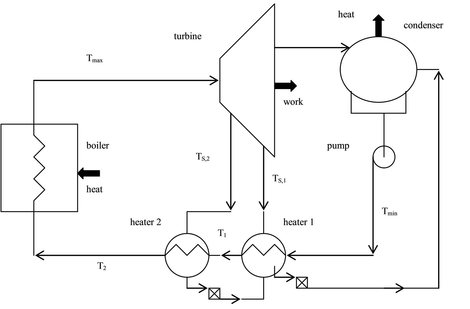
Figure 1. Schematic figure of a typical thermal power plant that employs two closed feed water heater.
maintenance and operation cost to the original cost. Additionally, optimum effectiveness of the feed water heaters, critical number of feed water heaters, payback period and optimum operating temperatures of steam and feed water are obtained algebraically in the present formulation method in a few minutes with the help of practical formulae. A thorough search of the present literature showed that there were several studies about the feed water heaters [1-6]. All of these studies are not directly related to the present work. Original formulae are developed and presented finally.
2. Mathematical formulation
a) Optimum number of feed water heater stage:
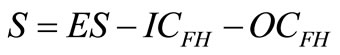
As a beginning, the amount of total life cycle savings, ES, as a result of feed water heater applications can be calculated as:
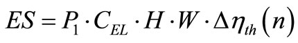 (1)
(1)
Increase in thermal efficiency  as a function of number of stage utilized, n, can be formulated by using the data [7] of a sample problem as follows:
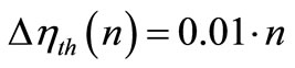 (2)
(2)
Initial cost of the feed water heaters, ICFH, is evaluated by the following equality by using the cost data [8].
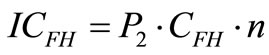 (3)
(3)
The operation cost of feed water heater, OCFH, can be calculated by the following formula:
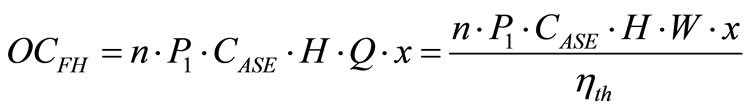 (4)
(4)
Cost of steam, CSE, in cents per GJ, extracted from the turbine strongly depends upon the extracted steam temperature and so the number of extraction stage as in the following form [9]:
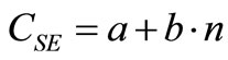 (5)
(5)
Average value of the steam for n stage, CASE, can be determined by the following.
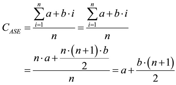 (6)
(6)
The operation cost of feed water heater can then be rewritten as:
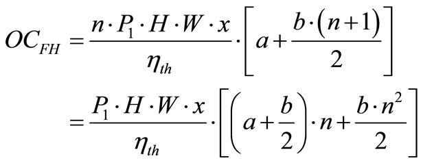 (7)
(7)
Net savings from the feed water heater application, S, can be obtained by the following formula:
 (8)
(8)
Net savings function can be extended to Equation (9) by taking the unit conversion factor, 3.6 × 10⁻⁵, into consideration:
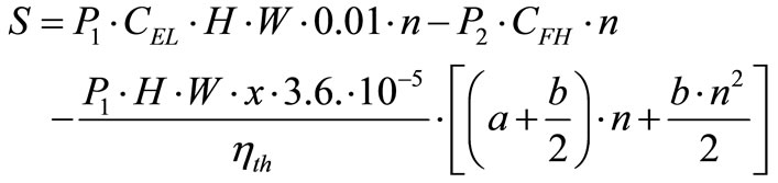 (9)
(9)
The optimum number of feed water heater stage, nopt, can be determined by deriving the Equation (9) with respect to number of stage algebraically as in the following form:
 (10)
(10)
Equation (10) yields to:
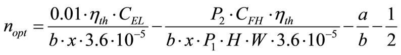 (11)
(11)
The second derivative of the net savings function indicates a local maximum.
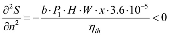 (12)
(12)
When i ≠ d, then the value of the P1, in years, is calculated by the following [13]:
 (13)
(13)
and whether i = d, economic parameter P1 can be evaluated as [14]
 (14)
(14)
The ratio of the life cycle expenditure to the first original cost, P2, is defined by the following Equation [15]:
 (15)
(15)
The critical value of number of stage, ncrit, can be determined easily by setting the net savings function into zero as follows:
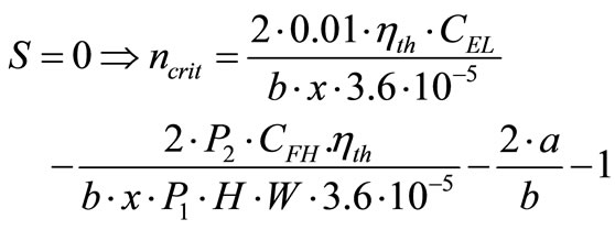 (16)
(16)
The time of payback, NP, is calculated by equalizing net savings into zero for optimum number of feed water heaters. For i = d condition:
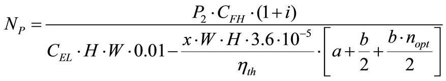 (17)
(17)
and if i ≠ d then:
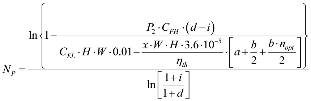 (18)
(18)
b) Optimum heat transfer area distribution between feed water heaters:
The optimum steam temperature distribution through the feed water heaters,  , is given by Ref. [7].
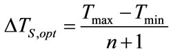 (19)
(19)
Temperatures of extracted steam in each of the two feed water heaters, Ts,1 and Ts,2 are determined by the following equalities.
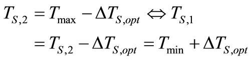 (20)
(20)
One can evaluate the net savings function, S, when using the extracted steam instead of using more expensive steam available in boiler as:
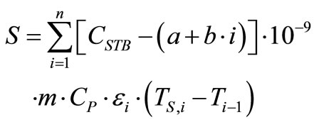 (21)
(21)
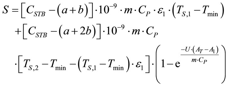
The savings function can be expanded to following equation for the two feed water heaters:
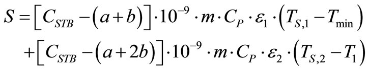 (22)
(22)
The temperature of feed water leaving the first feed water heater, T1, is:
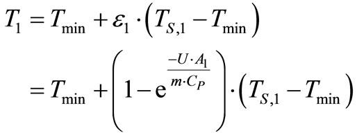 (23)
(23)
Effectiveness of the feed water heaters,  and
and , can be formulated as in following:
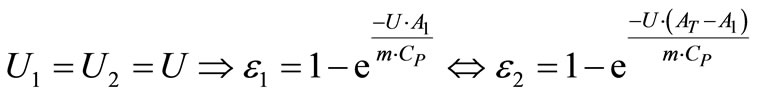 (24)
(24)
The help of equations above as can reformulate net savings function, in cents/sec, by considering a unit conversion factor of 10–9.
 (25)
(25)
It can be introduced alternatively as:
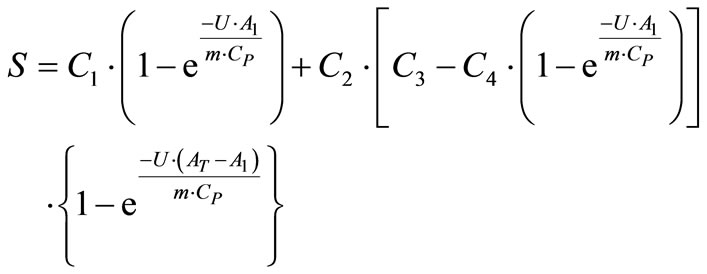 (26)
(26)
Or in more explicit form:
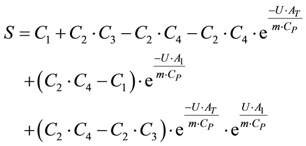 (27)
(27)
Derivative of savings function as in Equation (27) with respect to area of heat transfer of first feed water heater is as in following equality.
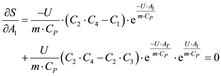 (28)
(28)
Equation (28) leads to:
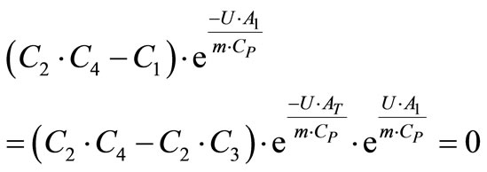 (29)
(29)
Equation (28) is set into zero as in Equation (29) and solved to get optimal value of the heat transfer area of the first heater, A.
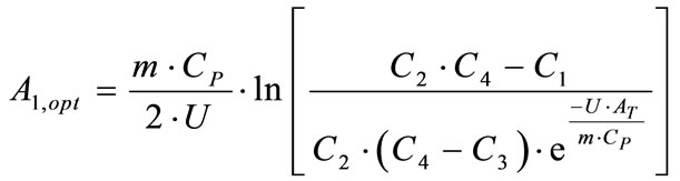 (30)
(30)
The second derivative of the net savings function with respect to A, (¶2S/¶A2) is calculated by using this specific optimum area value in the second derivative, and result is found to be always negative, which indicates a local maximum point.
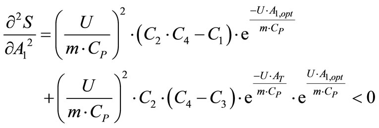 (31)
(31)
since
 (32)
(32)
where:
 (33)
(33)
 (34)
(34)
 (35)
(35)
 (36)
(36)
Temperature of feed water after the second feed water heater, T2, can be determined via using optimum area of heat transfer in effectiveness of the second feed water heater as presented in Equation (24).
 (37)
(37)
3. Results and Discussion
For a typical feed water design and sizing problem [9], it is given that a = 5, b = 8, AT is predetermined as 1000 m2 by a similar optimization method as illustrated in [11],

Table 1. Optimum operating parameters for the thermal power plant with two feed water heaters.

Table 2. Net savings values for various number of feed water heater.

Table 3. Net savings values for various area of heat transfer for the first heater.
CFH = 75000 $/stage, i = d = 0.10, CSTB = 60 cents/GJ, CEL = 0.07 $/(kW·hr), x = 0.1, W = 1000 kW, ηth= 0.35, H = 8760 hr/yr, N = 20 years, m = 100 kg/s, Cp = 4187 J/(kg·K), U1 = U2 = U = 2800 W/(m2·K), Tmin = 32 C, Tmax = 450 C, M s = 0, R v = 0. The optimum number of stage is calculated by means of Equation (11) as nopt = 1.659 and the optimum area of heat transfer for the first feed water heater is calculated as A1,opt = 381.15 m2 by using Equation (30). One can select 1 or 2 feed water heater, but since two feed water heater stages yields greater savings, selecting two stages will be more efficient. It can be deduced that savings is strongly depends upon number of stages. Critical number of feed water at which net savings is zero is determined as 3.318 and the payback period as 17.9 years for this sample problem. The values of net life cycle savings are plotted in Figures 2 and 3. It can be deduced that there exists a local maximum value in feed water applications. Excessive or deficient number of feed water heater stage will not be cost effective beyond the optimum number of feed water heater. The corresponding values of optimum water and steam temperatures and effectiveness values of feed water heaters are listed in Table 1. Effectiveness of second feed water heater is greater than the first feed water heater since the area of second feed water heater is greater than that for the first one. The net total life cycle savings values are presented in Tables 2 and 3 also.
It is clear that there exist good thermo-economic performances at the optimum points in Tables 2 and 3. Net savings is a maximum when the number of stage is 2 as in Table 2. Maximum net savings is 4.9278 cents per second as the heat transfer area of the first feed water heater is 381.17 m2 as shown in Table 3.
4. Summary
The optimum thermo-economic performance of feed water heaters are calculated at which maximum savings occurs in thermal power plants. The validity of the opti
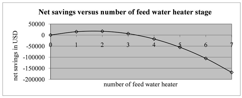
Figure 2. Variation of net savings versus number of feed water heater.
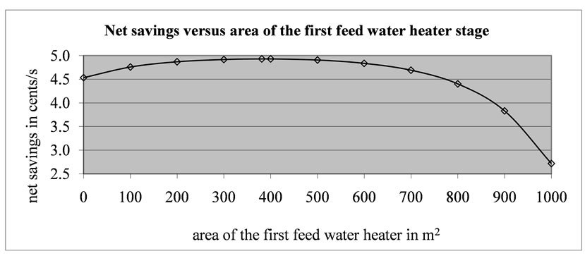
Figure 3. Variation of total cost versus area of the first feed water heater.
mization formulation is checked. Feed water heaters must be designed close to this optimum point. The present formulae may seem to be helpful for the designers and manufacturers of these systems. There is no previous work for comparison of present optimization results.
REFERENCES
- M. A. Habib, S. A. M. Said and I. Al-Zaharna, “Thermodynamic Optimization of Reheat Regenerative Thermal Power Plants,” Applied Energy, Vol. 63, No. 1, 1999, pp. 17-34. doi:10.1016/S0306-2619(99)00017-3
- M. K. Gupta and S. C. Kaushik, “Exergy Analysis and Investigation for Various Feed Water Heaters of Direct Steam Generation Solar-Thermal Power Plant,” Renewable Energy, Vol. 63, No. 6, 2010, pp. 1228-1235. doi:10.1016/j.renene.2009.09.007
- A. M. Bassily, “Modelling and Numerical Optimization of Dualand Triple-Pressure Combined Cycles,” Proceedings of the Institution of Mechanical Engineers Part A: Journal of Power and Energy, Vol. 218, No. A2, 2004, pp. 97-109. doi:10.1243/095765004773644102
- S. K. Tyagy, G. M. Chen and Q. Wang, “Thermodynamic Analysis and Parametric Study of an Irreversible Regenerative-Intercooled-Reheat Brayton Cycle,” International Journal of Thermal Science, Vol. 45, No. 8, 2006, pp. 829-840. doi:10.1016/j.ijthermalsci.2005.10.011
- S. K. Tyagi, S. W. Wang and S. R. Park, “Performance Criteria on Different Pressure Ratios of an Irreversible Modified Complex Brayton Cycle,” Indian Journal of Pure & Applied Physics, Vol. 46, No. 8, 2008, pp. 565-574.
- A. Bolattürk and M. Kanoglu, “An Investigation of Energy versus Exergy Based Optimization for Power Cycles,” Energy Exploration and Exploitation, Vol. 24, No. 4-5, 2006, pp. 243-257.
- A. W. Culp, “Principles of Energy Conversion,” 2nd Edition, Mc Graw-Hill, Singapore, 1991.
- L. C. Burmeister, “Elements of Thermal-Fluid System Design,” Prentice Hall, New Jersey, 1998.
- W. F. Stoecker, “Design of Thermal Systems,” 3rd Edition, Mc Graw-Hill, New York, 1989.
- J. A. Duffie and W. A. Beckman, “Solar Engineering of Thermal Processes,” Jhon Wiley and Sons, New York, 1980.
- M. S. Söylemez, “On the Optimum Heat Exchanger Sizing for Waste Heat Recovery,” Energy Conversion and Management, Vol. 41, No. 13, 2000, pp. 1419-1427.
Nomenclature
a Coefficient for steam cost function
AT Total heat transfer area of heaters, (m2)
A1 Heat transfer area of the first heater, (m2)
A1,opt Optimum heat transfer area of the first heater, (m2)
b Coefficient for steam cost function
CFH First cost of the each feed water heater, ($/m2)
CASE Average unit cost of the energy by steam, (cents/GJ)
CEL Unit cost of the electricity produced by the turbine, [$/(kW·hr)]
CSE Unit cost of the energy by steam as a function of extraction temperature, (cents/GJ)
CSTB Unit cost of the energy by steam in the boiler, (cents/GJ)
CP Specific heat of the water, [J/(kg·K)]
C1 Constant defined in Equation (33), (cents/s)
C2 Constant defined in Equation (34), [cents/(s·K)]
C3 Constant defined in Equation (35), (C)
C4 Constant defined in Equation (36), (C)
d Market discount rate in fraction
ES Savings from extra electricity production, ($)
H Annual time of operation, (hr/yr)
i Energy price rate in fraction
ICFH Initial cost of feed water heaters, ($)
m Mass flow rate of circulating feed water, (kg/s)
MS Ratio of annual maintanence and operation cost into first original cost
n Number of feed water heater
ncrit Critical number of feed water heater
nopt Optimum number of feed water heater
N Technical life of the thermal power plant, (yr)
NP Payback period, (yr)
OCFH Operation (energy) cost of feed water heater, ($)
P1 Ratio of the life cycle energy cost or savings to that for the first year, (yr)
P2 Ratio of the life cycle expenditures incurred because of the additional capital investment to the initial investment
Q Heat input to boiler, (kW)
Rv Ratio of resale value of the system into the first original cost
S Net savings, ($)
Tmax Maximum steam temperature, (C)
Tmin Minimum (condenser) temperature, (C)
Ti Temperature of water after the i th feed water heater, (C)
TS,i Temperature of steam extracted to i th feed water heater, (C)
TS,1 Temperature of steam extracted to first feed water heater, (C)
TS,2 Temperature of steam extracted to second feed water heater, (C)
T1 Temperature of feed water when leaving the first feed water heater, (C)
T2 Temperature of feed water when leaving the second feed water heater, (C)
U Overall heat transfer coefficient of the feed water heater, [W/(m2·K)]
U1 Overall heat transfer coefficient of the first feed water heater, [W/(m2·K)]
U2 Overall heat transfer coefficient of the second feed water heater, [W/(m2·K)]
x Mass fraction of steam entering into each feed water heater
W Electrical power generation capacity of thermal power plant, (kW)
ΔTS,opt Optimum steam temperature difference across two neighbor feed water heaters, (C)
Δηth Increase in thermal efficiency of the thermal power plant
εi Effectiveness of the i th feed water heater
ε1 Effectiveness of first feed water heater
ε2 Effectiveness of the second feed water heater
ηth Thermal efficiency of the thermal power plant.