Engineering
Vol. 3 No. 4 (2011) , Article ID: 4601 , 4 pages DOI:10.4236/eng.2011.34046
Formation of X-120 M Line Pipe through J-C-O-E Technique
M S University of Baroda, Vadodara, India
E-mail: jaidev.chandel@jindalsaw.com, singhnandlal@gmail.com
Received February 12, 2011; revised March 16, 2011; accepted March 21, 2011
Keywords: Line Pipe, J-C-O-E Line Pipe Manufacturing, Spring Back, TMCP and Accelerated Cooling, Slab Preheating, Rough Rolling, Finish Rolling
ABSTRACT
The line pipe forming operation can be divided into two parts, first is to achieve the required shape in terms of curvature and ovality after formation of the line pipe. The curvature and ovality ultimately affects the final dimensional controls at the later stage i.e. after mechanical expansion of the line pipe. The second part is to make right welding joint geometry to make the final long seam weld of line pipe. The welding joint geometry ultimately controls soundness of final seam weld at later stage i.e. during submerged arc welding of the line pipe. As far as curvature or shape of line pipe is concerned, important operation is making the required curvature along the edges of TMCP and ACC (Thermo mechanical controlled processing and accelerated cooling process) plate for line pipe (Plate Edge Crimping press) up to the 150 mm in width minimum and forming of the line pipe at J-C-O press. The selection of dies with proper hardness and curvature in both the operation plays a vital role in the formation of line pipes. The main parameters of selection dies (Tools) are size of line pipe for which dies/tools are to be made i.e. the diameter of line pipe, thickness of line pipe and most important is grade of line pipe (Strength level). The grade or strength level decides amount of spring back behavior of the steel Plate. The spring back behavior again varies from steel mill to steel mill in the same grade of HR plate. This is because the each steel mill has its own manufacturing procedures to produce the TMCP and ACC plate. The plate for line pipe is produced through TMCP (Thermo mechanical controlled processing) and accelerated cooling process. In this process the strength level is achieved by the chemical composition of the slab, thickness of the slab, reheating temperature, roughing temperature at which reduction in the thickness, finish rolling temperature and finally the accelerated cooling temperature rate.
1. Introduction
The most of the trial X-120M line pipes were made through UOE route in the world [1], for safe line pipe forming new tools for U-O-E process has to be developed to reduce the danger of pipe failure during mechanical expansion. During mechanical expansion the line pipe experienced linear cracks due to improper curvature (i.e. the positive/negative peaking at the weld) at toe of the weld i.e. from HAZ portion. A low carbon and low Pcm steel with “V-Nb-Ti-B” micro alloying concept is used. The large spring back that occurs during the U-forming step of the U-O-E process is one of the most complex aspects in forming of X-120M line pipe. To handle this aspects FEM calculation were used to modify U-forming parameters and to optimize the shape of the U-press tool [1-7]. One of the greatest challenges in the line pipe forming of ultra-high strength plate with a relatively small wall thickness is large spring back due to the broader elastic range of a material with the high yield stress. Especially the U-forming step is affected by this spring back resulting to shell that cannot be inserted in to the O-Press. The newly calculated shape of the U-Press leads to a reduction of the spring back. Further it was assumed that ovality and peaking after O-ing were as well set to optimal value to avoid problems with the welding and expansion step of the line pipe production. The finished line pipe shape [8] was determined during manufacturing process and can be optimized by balancing manufacturing parameters, line pipe compression, and expansion. Through the optimization of crimping, Upress, and O-press operations, it is possible to control pipe diameter and ovality. The line pipe manufactured by the U-O-E process undergoes various strain cycles, both tensile and compressive. The combination of these cycles affects overall behavior of the material in compression. This is known as the Bauschinger effect. Corus Tubes, over a period of years, observed that the results it obtained from the forming process often yielded higher collapse strengths than those obtained when any of the standard equations were applied. Examination of equation parameters suggested that this benefit could result either greater pipe roundness or increased pipe compressive strength. This led to a research and process development program that provided greater understanding of the mechanisms at work during pipe forming. During line pipe forming [9], inner surface compressive and outer surface tensile strains are produced at the U-ing and O-ing stage of U-O-E line pipe forming. The large-diameter pipes [10] used in offshore applications is commonly manufactured by cold-forming plates through the U-O-E process. The plate is crimped along its edges, formed into a U-shape and then pressed into an O-shape between two semicircular dies. The line pipe is welded closed and then circumferentially expanded to obtain a highly circular shape. Crimping affects the shape of upper part of a U-O-E pipe. In particular, it effects the shape (and ovality) of U-O line pipe. It was found that crimp radii that are smaller than the inner and outer radii of the final line pipe results higher U-O collapse pressures. Furthermore, reducing length of the crimped part tends to increase the U-O collapse pressures. It was also found that if the current practice of expanding the diameter of the line pipe by about one percent is followed, both the negative and positive effects of crimping are usually erased. However, if alternate forming solutions such as under expansion are adopted, a more careful selection of the crimping dies can lead to improved collapse performance. The main crimp parameters effecting the line pipe shape are inner and outer radii, and the length of plate being crimped. Thus, a smaller inner die radius produces a rounder line pipe. The first step [11] of the manufacturing process of line pipe is the edge press, during this process, the upper tool is fixed and the lower tool is moved in upward direction. Then the forming process continues with the ‘U’ press, where the plate is formed into a U-shape. Afterwards, the forming process continues in the ‘O’ press, where circumferential compression is applied to form an O-shape. To achieve this, two semi-cylindrical dies press the Ushape. At the point of maximum compression, nodes of pipe are fixed in the horizontal edge at symmetrical axis. Finally, a radial expansion is applied in order to obtain the final shape of the line pipe.
As for as the manufacturing of line pipe through UOE technique is concerned, first very high forming force (tonnage) is required to form the line pipe and secondly the new tooling (very massive in nature) are required. The high tonnage requirement in formation of ultra high strength X-120M line pipe because the U and O forming steps have to be performed in the single stroke respectively. So manufacturing of ultra high strength X-120M line pipe through J-C-O-E technique is more convenient and cost effective as for as forming force (Tonnage) tooling are required. In J-C-O the formation is carried out by incremental pressing with required number of strokes to form the high strength line pipe with less forming force (Tonnage) and less amount of tooling. The spring back behavior of high strength steel X-120M line pipe can be controlled up to certain extent by controlling the depth of each stroke during the J-C-O formation. To achieve all these stages of X-120M line pipe forming, the required tooling has to be established to get the desired shape of line pipe.
2. Line Pipe Formation through J-C-O-E Technique
The forming of line pipe is nothing but giving shape to TMCP (Thermo mechanical controlled processing) and accelerated cooling processed plate into line pipe at various stages. The formation of line pipe from TMCP plate mainly consist of trimming of TMCP plate to required width with help of milling of edges of the said plate for particular size and parallely making weld joint geometry during the trimming operation known as ‘edge milling’ as shown in figure 1. The milled plate is then formed by bending/forming of edges of the said plate to required radius along the length of plate for particular size of line pipe is known as ‘edge crimping’ as shown in figure 2. The edge crimped plate then formed to line pipe shape through J-C-O process with incremental pressing to the required radius of the line pipe by making first ‘J-shape’ then ‘C-shape’ and finally O-shape is known as ‘J-C-Oforming’ and after long seam welding the welded line pipe is mechanically expanded from inside to the required diameter of particular size of the line pipe to achieve the final dimensions as shown in figure 3.
The line pipe forming operations can be divided into four categories on the basis for line pipe manufacturing at different stages namely plate edge milling, plate edge crimping, J-C-O forming and mechanical expansion.

Figure 1. Plate width after edge milling process.


Figure 2. Sketch of crimping process.

Figure 3. Sketch of pipe forming process J-C-O-E.
2.1. Plate Edge Milling
Plate edge milling consists of 600 mm diameter cutter with 40˚, 48 numbers cartridges for trimming of plate edges to the required width and also to make weld joint geometry as shown in the figure 4.
The weld joint geometry used during the study in the line pipe manufacturing was double Y-joint which has three dimensions namely upper bevel, lower bevel and root face as shown in the figure 5. The cartridges for insert has been designed to produce the 40˚ bevel angle at lower, upper bevel and 2˚ angle at root face with a flexibility to get desired dimensions for upper, lower bevel and root face of ultra high strength TMCP steel plate. The 2˚ angle at root face is to get zero gaps at the time of tack welding of line pipe as shown in the figure 6. The gap at root face is not desirable during tack welding fit up, as this end up with defects like porosity and slag inclusion during the final submerged arc weld.
2.2. Plate Edge Crimping
The plate edge crimping operation in line pipe manufacturing is very critical as for as the final dimensions after mechanical expansion of line pipe around the weld of long seam are concerned. The final dimensions of line pipe around weld of the long seam are controlled through plate edge crimping along the length by getting required radius in crimped edges of the plate. The improper plate edge crimping would end up with peaking (positive or negative) at the weld and localized flatness in crimped area after mechanical expansion. The under edge crimping will produce the positive peaking and over edge crimping will produce the negative peaking. These dimen-

Figure 4. Plate edge milling cutter with 40˚, 48 numbers cartridges.
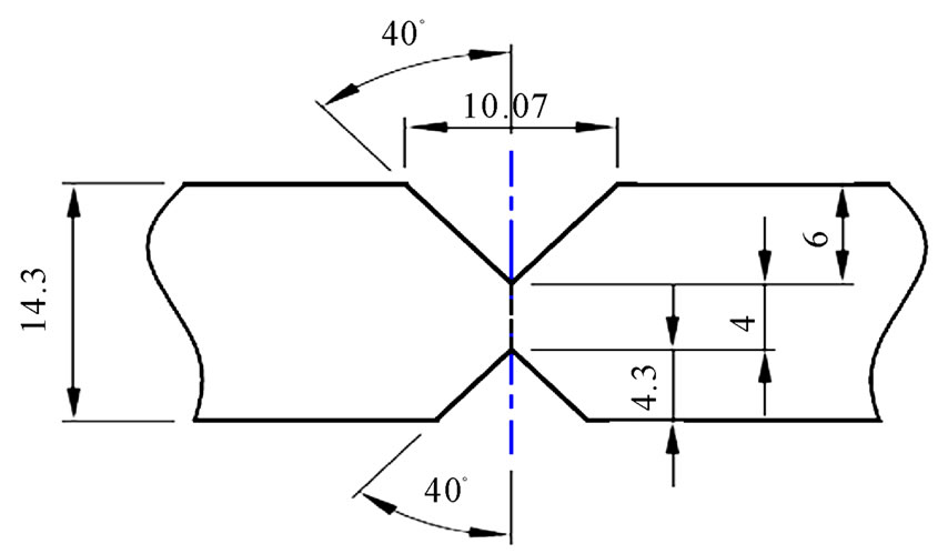
Figure 5. Weld joint geometry for line pipe.
sional defects are not acceptable as per line pipe manufacturing specifications. As per API-5L the limit for these defects is 1.59 mm maximum after mechanical expansion. From the manufacturing point of view the peaking beyond certain limit cannot be rectified at mechanical expander and there are chances of fracture of line pipe from the toe of the long seam weld, if the peaking generated at the crimping stage is more than the standard operating procedure. The as-weld is the cast structure and no treatment has been given in standard line pipe manufacturing operation and direct expansion of the weld is not acceptable as per line pipe manufacturing specifications. During mechanical expansion operation if peaking is more, then the positive peaking generate crack at inside weld toe (fusion line) and vice versa. The standard operating procedure in line pipe manufacturing is to control peaking at plate edge crimping stage itself by designing the plate edge crimping tools/dies accordingly.
The designing of the plate edge crimping dies has two equally important aspects, first is material and its treatment and second is the dimensions (thickness and radii). These dies are made out of low alloy steel and induction hardened to 45-48 HRC to have the wear resistance of working area and sufficient wall thickness of dies as shown in figure 7.
The radius of plate edge crimping dies is decided with respect to the diameter, thickness and grade of the line pipe. The diameter is deciding factor of outer die radius, diameter and thickness is the deciding factor for the radius of the inside die of the plate edge crimping. The grade/strength is equally important as it shows the spring
 (a)
(a) (b)
(b)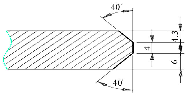 (c)
(c) (d)
(d)
Figure 6. Effect of angle at root face.

Figure 7. Crimping tools for line pipe.
back behavior of the TMCP steel which has to be taken into account while deciding the radii of inside as well outside plate edge crimping dies. The diameter of line pipe is fixed at plate edge milling (with trimming) stage by fixing the width of the plate. The width of plate is nothing but circumference of the pipe minus percentage expansion of line pipe diameter. The milling width of the plate for line pipe manufacturing can be expressed as

where ‘MW’ is the milled width of the plate for line pipe, ‘D’ is Nominal outside diameter of the final line pipe, ‘t’ is Actual thickness of the TMCP plate, ‘ΔD’ is the percentage of expansion in diameter to achieve the nominal diameter after mechanical expansion and Π is the constant of value 3.14259. The line pipe diameter before expansion can be expressed in terms of the width/circumference of the plate.


where ‘CBE’ is the circumference before forming of line pipe, ‘dBE’ is outside diameter before forming or ‘dBE’ is equal to  and
and  is the constant of value 3.14259. On the basis of diameter of the line pipe before forming the inside plate edge crimping die and plate edge crimping outside die diameter can be expressed as
 where ‘dCIN’ is the inside crimping die diameter and ‘dCOUT’ is outside crimping die diameter. Ideally this will be the diameters of the crimping dies for plate edge crimping of the line pipe. But there is one unknown factor which is known as spring back. So the spring back has to be considered while deciding the dies radii of plate edge crimping. Therefore the dies Radii is nothing but the percentage of the shape deviation from the ideal shape (respective pipe radius), so by including the said parameter the radius of the inside as well outside crimping dies can be expressed as below.


where ‘rCIN’ is the inside crimping die radius, ‘rCOUT’ is outside crimping die radius and ‘ψ’ is the percentage spring back factor for line pipe steel. For grade X-70, the ψ is approximately 10% of the line pipe radius before forming and for X-80; the ‘ψ’ is typically 15% - 20% of the radius of the line pipe before forming. For X-120M, ‘ψ’ is taken as 30% to the respective radius of the line pipe before forming. The diameter of plate edge crimping template is nothing but the nominal diameter minus thickness and minus percentage of the expansion. The diameter of the template for outside diameter and inside diameter plate edge crimping is


Therefore the respective radii for plate edge crimping are


where ‘dTIN’ is the inside crimping Template diameter, ‘dTOUT’ is outside crimping Template diameter, ‘rTIN’ is the inside crimping template radius and ‘rTOUT’ is outside crimping Template radius. These templates are used to verify the correctness of the plate edge crimping profile to ensure the proper function of the operation.
2.3. J-C-O Forming
The J-C-O forming operation in line pipe manufacturing is very critical as for as the final dimensions after mechanical expansion of the line pipe around circumference are concerned. The final dimensions of the line pipe around the circumference are controlled through forming of the plate by getting the required radius in the line pipe of formed plate. The improper forming is end up with oval and localized flatness in the formed area after mechanical expansion. These dimensional defects are not acceptable as per line pipe manufacturing specifications. As per API-5L the limit for these defects is 1.59 mm maximum for localized flatness and one percent for ovality (Deviation from the circularity) after mechanical expansion. From the manufacturing point of view localized flatness and ovality beyond certain limit cannot be rectified at mechanical expander. The standard operating procedure in line pipe manufacturing is to control the localized flatness and ovality at the J-C-O forming stage itself by designing the J-C-O line pipe forming dies accordingly.
The designing of the J-C-O line pipe forming dies has two equally important aspects, first is material and its treatment and second is the dimensions (thickness and radii). These dies are made out of low alloy steel and induction hardened to 45-48 HRC to have the wear resistance of the working area and sufficient wall thickness of dies as shown in figure 8. The radius of the J-C-O line pipe forming dies is decided with respect to the diameter, thickness and grade of the line pipe.
The diameter and thickness is the deciding factor for the radius of the J-C-O line pipe forming die. The grade/ strength is equally important as it shows the spring back behavior of the TMCP steel which has to be taken into account while deciding the radius of the J-C-O line pipe forming dies. The diameter of line pipe is fixed at the width milling (trimming) stage by fixing the width of the plate. The radius of the J-C-O line pipe forming die and the verification template can be designed on the same hypothesis as for inside plate edge crimping dies.
2.4. Mechanical Expansion
The mechanical expansion operation in line pipe manufacturing is very critical as for as the final dimensions after the long seam welding of line pipe are concerned. The final dimensions of the line pipe around the weld of the long seam and along the circumference. The as-weld is the cast structure and no treatment has been given in standard line pipe manufacturing operation and direct expansion of the weld is not acceptable as per the line pipe manufacturing specifications. During mechanical expansion the inside seam weld of line pipe should not be in contact with expander die. In one of the expander die there is slot of 5 mm deep and 50 mm wide for locating position of the inside weld so that it should never be in contact with expander die during the expansion operation
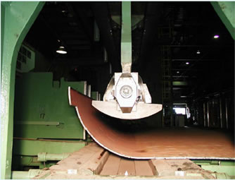
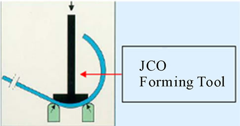
Figure 8. J-C-O tools for line pipe.
as shown in the figure 9, as the expansion mark on the weld bead is not acceptable in line pipe manufacturing specifications.
The final dimensions of the line pipe which are controlled at expander are peaking at weld, flatness, ovality, straightness, and diameter. These dimensions again depend upon the tool design and the percentage of expansion of the line pipe. The tooling’s of which are playing important role during expansion of line pipe first is expansion segment, second is wedge (in conical shape) on which the expansion dies are fitted and third one is the pipe sport roll through/on which line pipe is moving reverse and forward during the expansion. The designing of the expander tooling’s has two equally important aspects, first is material and its treatment and second is the dimensions of the respective tool (thickness and radii). These expansion dies are made out of die steel and volume hardened and tempered to 55-88 HRC to have wear resistance of the working area and sufficient wall thickness of dies as shown in figure 9. The wedge is playing a very important role as the expansion segment is moving under expansion load on it and if the surface finish and its self lubricating properties should be properly designed. The material and its heat treatment are very critical. Therefore the new wedge of ADI material has been redesigned to have proper strength and wear resistance with self lubricating properties. The new wedge ADI material with modularity count 103-120/mm², matrix of the structure is pearlitic in nature and ultimate tensile strength is 790 MPa at hardness 32 HRC. The wedge material ADI is volume hardened and tempered to 45-48 HRC satisfactorily. The radii of the expansion segments of the expander are decided with respect to the diameter, thickness and grade of the line pipe. The diameter and thickness are the deciding factor for the radii of the expansion segment of the expander. The grade/strength is equally important as it shows the spring back behavior of the TMCP steel which has to be taken into account while deciding the radii of the expansion segment of the expander. The diameter of line pipe is fixed at the width milling (trimming) stage by fixing the width of the plate. The radii of the expansion segments can design on the same hypothesis as for inside plate edge crimping die as stated above. The radius of the verification template is the final nominal radius of the line pipe.
3. Experimental Technique
During the experiment a low carbon, low Pcm steel with V-Nb-Ti-B microalloyed X-120M steel with chemical composition as shown in the table 1 has been taken for line pipe formation through J-C-O-E technique.
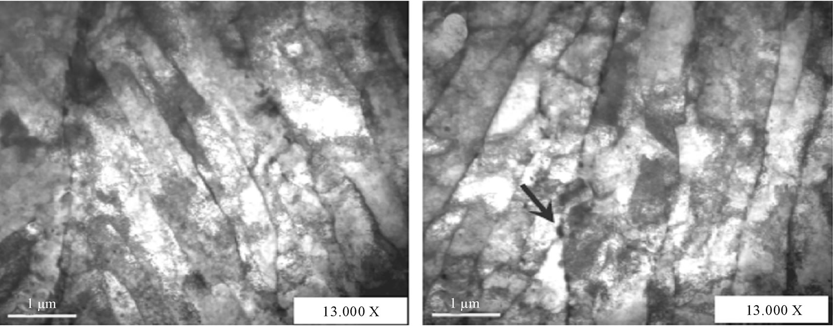
The above steel used in the in the experiment having the pan cake type bainitic microstructure with high dislocation density as shown by micrographs taken by light microscopy, scanning electron microscopy and transmission electron microscopy in figures 10-12 respectively.
The experimental X-120M steel has the fine precipitates of metallic carbides in transmission electron microscopy as shown in figure 13. The mechanical properties of the X-120M experimental steel are shown in table 2 and 3.
On the basis of the hypothesis discussed in the previous section (Plate Edge Milling, Plate Edge Crimping, J-C-O-E Formation and Mechanical Expansion) for tools/dies design for line pipe formation, one set of complete tools/dies has been designed and manufactured for line pipe of 18” (457.2 mm) of diameter and thickness is 14.3 mm of API-5L grade X-120M. The plate width and radius of the dies of plate crimping press, forming and expansion are shown in table 4. The Same radius templates were also made to check the profile of the formed pipe at all stages as per the table 4.
One pipe was formed covering all activities like tab joining, Plate Ultrasonic Testing, Milling, washing, Continuous tack welding, cleaning and submerged arc weld-

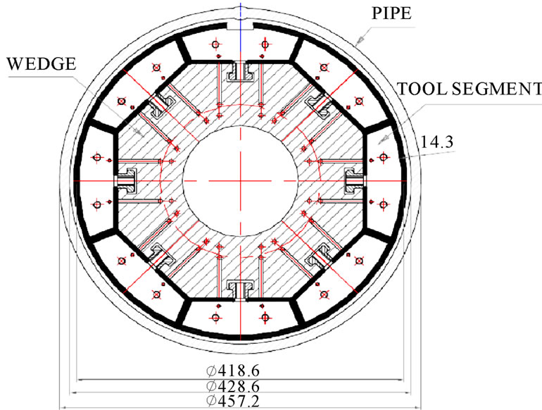
Figure 9. Rectangular slotted expander die to accommodate the weld seam.

Table 1. Chemical composition of experimental X-120 M steel.

Figure 10. Light optical Micrographs showing bainitic type microstructure.
ing. The submerged arc welding has been carried out as per the established welding procedure for X-120M as mentioned elsewhere. The shape of the line pipe comes out like egg shape, the ovality at F-end was 26 mm and at T-end is 30 mm, peaking at F and T-end was 6 and 7 mm respectively and the straightness was 20 mm. The dimensions of the line pipe after forming and submerged weld were on very higher side and the profile was also not matching with the profile template. During the mechanical expansion the line pipe failed because the dimensional defects could not be rectified with expander as stated earlier and due to these dimensional defects the compressive strength which is more than the strength of the line pipe [9]. The crack initiated at the inside weld toe i.e. fusion line due to the very high positive peaking and poor profile as shown in figure 14.
The tools/dies design is revisited and found radius of the tools is not as per the profile required for line pipe. The tools are redesigned with the spring back of 40% of the diameter of the pipe. The plate width and radius of the dies of plate crimping press, forming and expansion are shown in table 5. The same radius templates were also made to check the profile of the formed line pipe.
Again one line pipe of 18" × 14.3 mm of X-120M is

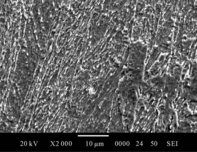
Figure 11. SEM micrographs showing pan cake bainitic type microstructure.
 (a)
(a) (b)
(b)
Figure 12. Bright field TEM micrographs showing lath-type and bainitic-type ferrite with high dislocation density. Interlath carbides are indicated with arrows.
 (a)
(a) (b)
(b)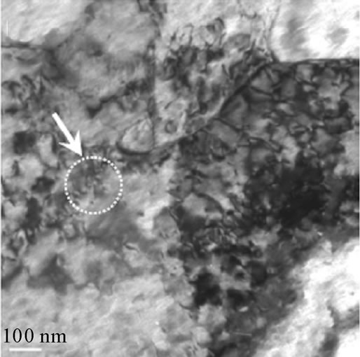 (c)
(c)
Figure 13. (a) and (b) Bright field TEM micrographs showing fine precipitates in ferrite matrix; (c) SAD pattern for the fine MC type carbides, where M = Nb or Ti.

Table 2. Tensile properties of experimental X-120 M steel.

Table 3. Charpy v-notch toughness of experimental X-120 M steel.
made through all the stations as mentioned above. The shape of the line pipe looks good as shown in the figure 14, the ovality at F-end was 10 mm and at T-end is 12 mm, peaking at F and T-end was 2 and 2.5 mm respectively and the straightness was 8 mm.
The dimensions of the line pipe after forming and submerged arc weld were satisfactory as per the standard line pipe manufacturing procedure and the profile matched with profile of template. Therefore all the parameter likes profile; peaking and ovality were within the limits acceptable. The line pipe expansion was carried out successful with ovality 3 mm - 4 mm, peaking 0.8 mm and straightness 7 mm at 0.9 - 1.0 percentage of expansion. The details of the forming, welding and finishing operations along with mechanical and physical properties will be discussed elsewhere.
4. Results and Discussion
The line pipe of size 18" × 14.3 mm has been formed from the plate produced through TMCP (Thermo mechanical controlled processing) and accelerated cooling process. The line pipe has been formed by the tools developed through various stages like plate edge miller, plate crimping, and J-C-O formation with one percent of expansion and spring back consideration of 30 percent.
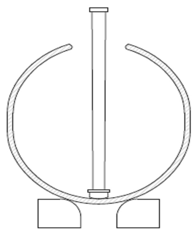
Figure 14. Poor profile of the line pipe.

Figure 15. Good profile of the line pipe.

Table 4. Calculation for forming tools.

Table 5. Calculation for forming tools.
The line pipe has been welded and expanded as per the tooling developed. The outcomes in terms of shape of the line pipe like egg shape, the ovality at F-end was 26 mm and at T-end is 30 mm, peaking at F and T-end was 6 and 7 mm respectively and the straightness was 20 mm. The dimensions of the line pipe after forming and submerged arc weld were on very higher side and profile did not match profile of template. During the mechanical expansion the line pipe failed because the dimensional defects could not be rectified with expander and due to these dimensional defects the compressive strength which is more than the strength of the line pipe. The crack initiated at inside weld toe i.e. fusion line due to very high positive peaking and poor profile.
The tools/dies design is revisited and found the radius of the tools is not as per the profile required for line pipe. The tools are redesigned with the spring back of 40 percent of the diameter of the pipe. The line pipe of 18" × 14.3 mm of X-120M was again made with new tooling through all the stations as mentioned above. The ovality at F-end was 10 mm and at T-end is 12 mm, peaking at F and T-end was 2 and 2.5 mm respectively and the straightness was 16 mm before mechanical expansion. The dimensions of the line pipe after forming and submerged weld were satisfactory as per the standard line pipe manufacturing procedure and the profile also matched with profile of template. Therefore all the parameter likes profile, peaking and ovality within the limit and line pipe expansion is successful with ovality 3 mm - 4 mm, peaking 0.8 mm and straightness 7 mm at 0.8 - 1.0 percentage of expansion.
Therefore spring back during the formation is unpredictable before actual formation happens. The spring back is a vital factor which needs to access correctly to decide the radius of tools/dies used at various stages of the line pipe forming. The radius of the tools/dies at every station of line pipe forming except the plate edge milling operation is playing a critical role in forming a line pipe with acceptable final dimensions and profile/curvature.
5. Acknowledgements
I am grateful to Prof. N L Singh (Department of Physics, M S University of Baroda, 392 002, India) for his endless support and encouragement during this study. I acknowledge the financial support from Welspun Gujarat Stahl Rohren Ltd. India and providing me the opportunity to pursue the experimental work in the line pipe mill.
6. REFERENCES
- H. G. Hillenbrand, A. Liessem, K. Biermann, C. J. Heckmann and V. Schwinn, “Development of Grade X120 Pipe Material for High Pressure Gas Transportation Lines,” 4th International Conference on Pipeline Technology, Ostend, 9-12 May 2004, pp. 1-9.
- H. G. Hillenbrand, A. Liessem, K. Biermann, C. J. Heckmann and V. Schwinn, “Development of High Strength Material and Pipe Production Technology for Grade X120 Linepipe,” International Pipeline Conference IPC Calgary, Alberta, 4-8 October 2004, pp. 1743-1749.
- H. G. Hillenbrand, A. Liessem, K. Biermann, C. J. Heckmann and V. Schwinn, “Development and Production of Linepipe Steels in Grade X100 and X120,” Seminar of X120 Grade High Performance Pipe Steels, Technical Conference, Beijing, 28-29 July 2005, pp. 1-11.
- A. H, E. Tsuru, T. Hara, M. Sugiyana, Y. Terada, H. Shinada, S. Ohkita, H. Morimpto, N. Doi, M. Murata, H. Miyazaki, E. Yamashita, T. Yoshida, N. Ayukawa, H. Akasaki, M. L. Macia, C. W. Petersen, J. Y. Koo, N. V. Bangaru and M. J. Luton, “Pipe Production Technology and Properties of X-120 Linepipe,” Proceedings of the 13th International Offshore and Polar Engineering Conference Honolulu, Hawaii, 25-30 May 2003, pp. 43-49.
- H. Asahi, T. Hara, E. Tsuru, Y. Terada, M. Sugiyama, N. Maruyama, H. Morimoto, K. Shinada, K. Koyama, M. Murata, N. Doi, H. Miyazaki, T. Yoshida, N. Ayukawa and H. Akasaki, “The Metallurgical Design of HighStrength Steel and Development of X120 UOE Line Pipe,” Pipeline Technology Proceedings, Belgium, Vol. 1, 9-13 May 2004, pp. 851-871.
- H. Asahi, E. Tsuru, S. Ohkita, N. Maruyama, K. Koyama, H. Akasaki, M. Murata, H. Miyazaki, T. Hara, H. Morimoto, M. Sugiyama, K. Shinada, Y. Terada, N. Ayukawa, N. Doi and T. Yoshida, “Development of UltraHighStrength Linepipe, X120,” Nippon Steel Technical Report No. 90, July 2004, UDC 669.14.018.292-462.2:621. 643.23.
- H. G. Hillenbrand, C. Kalwa and A. Liessem, “Technological Solution for Ultra-High Strength Gas Pipeline,” 1st International Conference on Super-High Strength Steels, Rome, 2-4 November 2005, pp 1-12.
- Technology Update, “Improved UOE Pipe,” Manufacturing Process Helps Meet Deepwater Pipeline Challenges, JPT, July 2008, pp. 26-29.
- G. Mannucci, G. Demofonti and H. G. Hillenbrand, “Fracture Properties of API X100 Gas Pipeline Steels,” EUROPIPE, EP/TP-39/01 en-2001.
- M. D. Herynk, S. Kyriakides, A. Onoufriou and H. D. Yun, “Effects of the UOE/UOC Pipe Manufacturing Processes on Pipe Collapse Pressure,” International Journal of Mechanical Sciences, Vol. 49, No. 5, 2007, pp. 533- 553. doi:10.1016/j.ijmecsci.2006.10.001
- J. Raffo, R. G. Toscano, L. Mantovano and E. N. Dvorkin, “Numerical Model of UOE Steel Pipe: Forming Process and Structural Behavior,” In: S. A. Elaskar, E. A. Pilotta and G. A. Torres, Eds., Mecanica Computacional, Vol. 26, October 2007, pp. 317-333.

