Open Journal of Fluid Dynamics
Vol.3 No.4(2013), Article ID:40445,9 pages DOI:10.4236/ojfd.2013.34037
Performance Evaluation of Heat Exchangers in OTEC Using Ammonia/Water Mixture as Working Fluid
Institute of Ocean Energy, Saga University, Saga, Japan
Email: 11634021@edu.cc.saga-u.ac.jp
Copyright © 2013 Takafumi Morisaki, Yasuyuki Ikegami. This is an open access article distributed under the Creative Commons Attribution License, which permits unrestricted use, distribution, and reproduction in any medium, provided the original work is properly cited.
Received September 4, 2013; revised October 4, 2013; accepted October 11, 2013
Keywords: Ammonia/Water Mixture; Evaporation and Condensation Pressure; OTEC; GMTD; LMTD
ABSTRACT
The ocean thermal energy conversion (OTEC) system is a promising solution to provide stable electricity supply. Although the available temperature difference in OTEC systems is small, an ammonia/water mixture as working fluid is expected to decrease irreversible losses in the heat exchangers and to improve system performance. However, in actual heat exchangers, an adequate temperature crossing does not occur in the condenser but in the evaporator. Therefore, clarification of this characteristic is important. To date, the logarithmic temperature difference (LMTD) method is used in performance evaluations of OTEC heat exchangers. This method is of limited use if physical properties of fluids vary. A generalized mean temperature difference (GMTD) method is introduced to perform this evaluation. As changes in fluid property values can be considered in the GMTD method, method dependencies on heat exchanger characteristics, effectiveness, and system characteristics can be studied. In particular, GMTD and LMTD using a pure substance were found to be almost equal. Mean temperature differences using mixtures as working fluid were higher in the evaporator, but lower in the condenser, from the GMTD method than from the LMTD method. For higher ammonia concentrations in ammonia/water mixtures, the mean temperature differences from both methods are different.
1. Introduction
Energy and environmental problems are becoming more critical; the development of natural energy is desired. Ocean thermal energy conversion (OTEC) using temperature differences between warm surface seawater and cold deep seawater can supply stable electrical power [1] integrated into a variety of applications, such as seawater desalination, residential cooling, and aquaculture [2-6]. In addition, the beneficial effects of OTEC systems on global warming and energy shortage problems seem promising. Oceans have a huge amount of stored thermal energy, although, the energy density is low. As an OTEC system operates in conditions of small temperature differences, an appropriate working fluid must have a low boiling point if it is to be used in a closed-cycle OTEC. The OTEC system requires warm water, cold seawater, and a working fluid pump power; the ratio of the warm and cold water pump power to output power is comparatively higher than that of conventional fossil power plants.
Research is continuing on the Rankine cycle which is the conventional closed-cycle process exploiting lowboiling-point working fluids such as ammonia. Using a pure substance as working fluid, the thermal efficiency of the OTEC cycle increases with decreasing irreversible losses in the cycle or increasing effective temperature difference, specifically the difference between evaporating and condensing temperatures of the working fluid. For that reason, it is necessary to decrease energy losses in the heat exchangers, namely to decrease the temperature difference between seawater and working fluid. This is done by increasing the heat transfer area or the overall heat transfer coefficient. Using non-azeotropic mixtures such as ammonia/water as working fluids in the OTEC cycle was proposed by Kalina in 1982 [7]. Uehara et al. [8] indicated that reducing the irreversible losses in heat exchangers using non-azeotropic mixtures leads to improvements in the thermal efficiency of the cycle. Furthermore, they focused on the Kalina cycle, and presented a new cycle using the ammonia/water mixture [9]. Several theoretical and experimental investigations have reported that thermal efficiency of such Kalina cycles is higher than that of the Rankine cycle using pure ammonia [10-15]. Other studies have reported that the effective temperature difference and heat transfer coefficient decrease with changes in concentration in the boundary layer during evaporation and condensation [16-18]. Previous studies have investigated the operating conditions and equipment of an experimental apparatus using ammonia/water mixtures to improve system performance. Ikegami et al. [19] performed experiments to investigate the influence of system performance on ammonia concentration in the mixture. The experiments were performed to assess the stability of the ammonia/water mixture power cycle [20]. The results from these experiments showed that it is critically important to enhance the performance of the condenser in increasing the performance of the total OTEC system. Furthermore, the characteristics of the ammonia/water mixture cycle have not as yet been thoroughly clarified experimentally.
To enhance the ammonia/water mixture cycle, clarification of the heat exchanger performance is extremely important. The traditional and effectual evaluation method of heat exchanger performance is the logarithmic mean temperature difference (LMTD) method but application of this method is limited to heat exchangers using working fluids having constant heat transfer coefficient and thermal properties. The generalized mean temperature difference (GMTD) method however enables variations in thermal properties in heat exchange processes to be included. Utamura et al. [21] first proposed the GMTD method, and applied it to evaluate the heat exchange process between hot water and supercritical carbon dioxide as a working fluid. As a result, validity of the GMTD method was proved. The GMTD is believed applicable in the evaluation of heat exchangers using ammonia/water although properties of the mixture are quite distinct. It is not clear whether the GMTD method is valid for heat exchangers using non-azeotropic mixtures as working fluid.
In this paper, clarification is obtained on the characteristics of heat exchanger using ammonia/water mixtures in improving cycle performance, achieved with the available methods of evaluation heat exchangers. A comparison is made between LMTD and the recently developed GMTD calculation methods as performed on the heat exchanger using ammonia/water mixture and the applicability of the GMTD method is assessed.
2. Temperature Change in Heat Exchangers with Ammonia/Water Mixture
In Figures 1(a) and (b), the distributions of the fluid temperature within the heat exchanger is given as a function of distance (Δx) and heat flow rate (ΔQ), respectively. The temperature variation of the ammonia/water mixture changes in the heat exchanger owing to the large difference between its boiling point and its dew point. Consequently, an increase in available exergy of the system is expected with this mixture as working fluid. From Figure 1(a), the improvement in heat transfer performance and the ratios of the working fluid temperature to the heat source temperature in the evaporator and to the cold In Figures 1(a) and (b), the distributions of the fluid
 (a)
(a) (b)
(b)
Figure 1. Temperature change in heat exchangers. Relationships between temperature and (a) length ratio and (b) heatflow-rate ratio for evaporator and condenser.
temperature within the heat exchanger is given as a function of distance (Δx) and heat flow rate (ΔQ), respectively. The temperature variation of the ammonia/water mixture changes in the heat exchanger owing to the large difference between its boiling point and its dew point. Consequently, an increase in available exergy of the system is expected with this mixture as working fluid. From Figure 1(a), the improvement in heat transfer performance and the ratios of the working fluid temperature to the heat source temperature in the evaporator and to the cold source temperature in the condenser are important when considering enhancing cycle performance. From Figure 1(b), the working fluid temperature is a convex curve of the heat flow rate. The working fluid temperature approaches the warm water temperature in the inlet and outlet of evaporator but approaches the cold water temperature in the middle of the condenser. The pinchpoint in particular is not well determined by the inlet and outlet temperatures in condenser. In addition, the traditional evaluation method underestimates heat transfer performance. Hence, the GMTD method, which accounts for the variation in the thermal properties, has been introduced for this performance evaluation. In contrast, for a pure ammonia working fluid, temperatures are constant in these heat exchangers because the thermal properties are stable.
2.1. Traditional Evaluation Method
The LMTD method has traditionally been used to evaluate the temperature difference between the heat source and the working fluid in a heat exchanger. The LMTD method is used only when the thermophysical properties of the local fluid in the heat exchanger and the overall heat transfer coefficient are constant. Hence, the fluid in the heat exchanger undergoes temperature changes as shown in Figure 2 with the horizontal axis conceptually representing the length. The LMTD method is expressed as follows:

Figure 2. Fluid temperatures in the counter-flow heat.
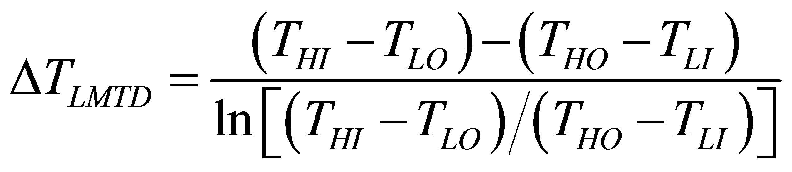 . (1)
. (1)
where THI, THO, TLI and TLO are the high and the low temperature fluids heat exchanger inlet and outlet temperatures.
2.2. Innovated Evaluation Method
For an improved evaluation, it is necessary to consider variations in the thermophysical properties that better reflect conditions within actual heat exchangers. Therefore, the calculation results of LMTD are compared with those of GMTD and assessed. Using Figure 2, the heat flow rate for the heat exchanger, dQ from x to x + dx, is calculated using:
 . (2)
. (2)
where Ui represents the overall heat transfer coefficient for the ith segment, mass flow rate of the warm or cold source, dAi is the heat transfer surface area, and ΔT is the temperature difference between highand low-temperature fluids. Integrating equation over all segments of the exchanger yields
 . (3)
. (3)
Then, the GMTD ΔTGMTD is defined as follows [21]:
 . (4)
. (4)
The temperature integral is approximated as:
 . (5)
. (5)
Therefore, the GMTD is calculated by:
 . (6)
. (6)
3. Comparison between Pure Ammonia and Ammonia/Water Mixture
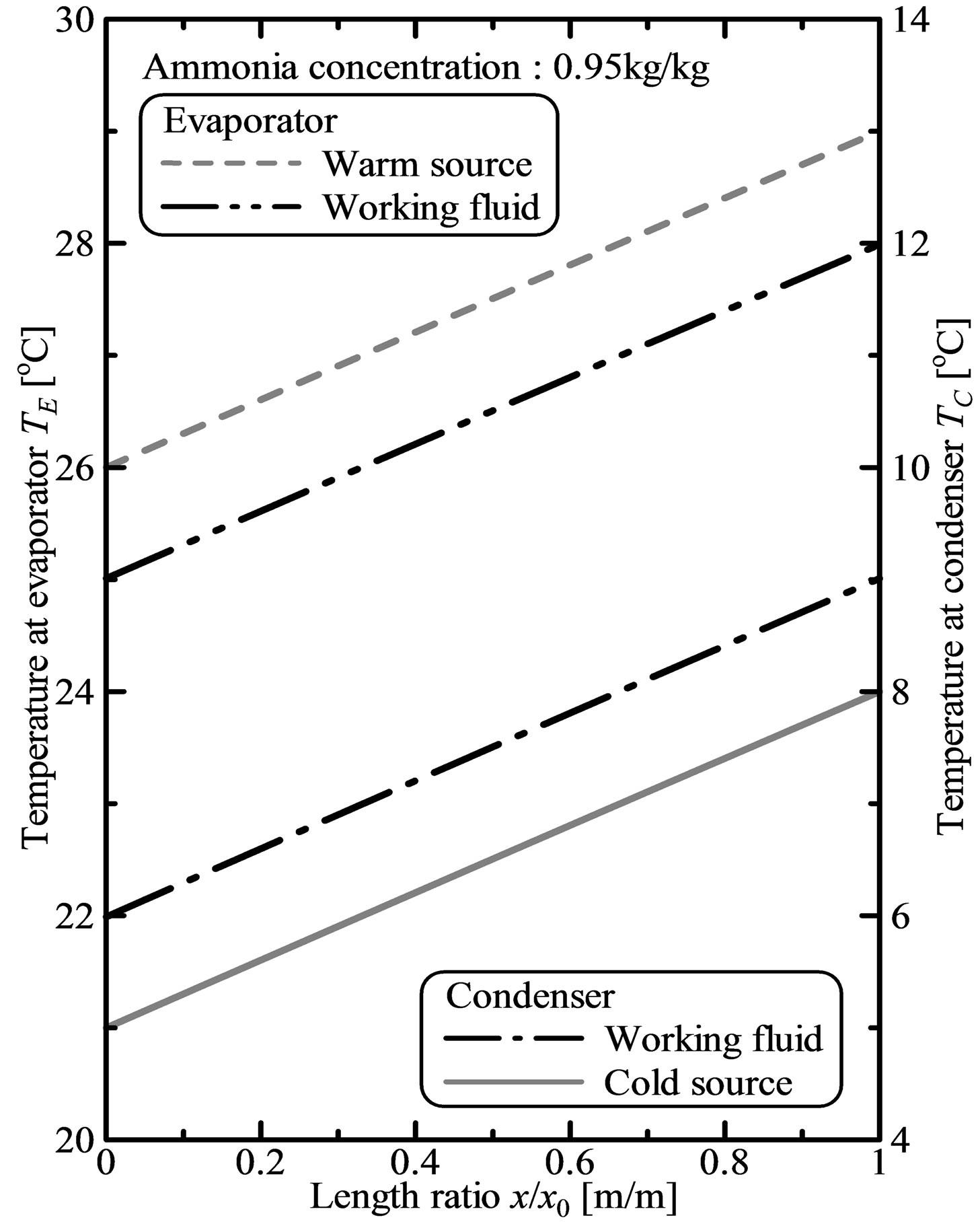
Figure 3 shows the correlation between GMTD and LMTD for the evaporator and the condenser calculated for both pure ammonia and ammonia/water mixture as working fluid. The evaporator and the condenser are counter-flow-type heat exchangers; both warm and cold sources are water; for the warm water, the inlet temperature is 28˚C, and the outlet temperature is 25˚C; for the cold water, the inlet temperature is 5˚C, and the outlet temperature is 8˚C. For pure ammonia, the evaporation temperature varied from 27.5˚C to 26.0˚C; the condensation temperature varied from 5.5˚C to 7.0˚C. For the ammonia/water mixture, the temperature at the evaporator inlet varied from 27.5˚C to 26.0˚C, and at the evaporator

Figure 3. Temperature change in heat exchangers.
the outlet temperature varied from 24.5 to 23.0; the temperature at the condenser inlet varied from 6.0˚C to 7.0˚C, and at the condenser outlet varied from 8.5˚C to 10.0˚C; the ammonia concentration is 0.95 kg/kg. The working fluids are assumed to be saturated liquid at the evaporator inlet and outlet, and saturated vapor at the condenser outlet and inlet. The physical properties of ammonia are evaluated using the P-PROPATH database, and those of ammonia/water mixture are evaluated using the M-PROPATH database (Ibrahim and Kelein) [22].
The mean temperature differences between pure ammonia and heat source from the LMTD method and GMTD method are almost equal, as seen in Figure 3. In contrast, the mean temperature difference between ammonia/water mixture and heat source is higher in the evaporator from the GMTD method than from the LMTD method, but lower in the condenser. The variation of working fluid temperature with heat-flow-rate ratio produces a convex downward curve, as seen in Figure 1(b). For the evaporator, the working fluid temperature approaches the warm water temperature at the evaporator inlet and outlet. The mean temperature difference is higher in the evaporator from the GMTD method than from the LMTD method. For the condenser, the working fluid temperature approaches the cold water temperature of the condenser. The mean temperature difference with the GMTD is lower than that with the LMTD method.
4. Mass-Flow-Rate Ratio Dependencies from GMTD and LMTD Models
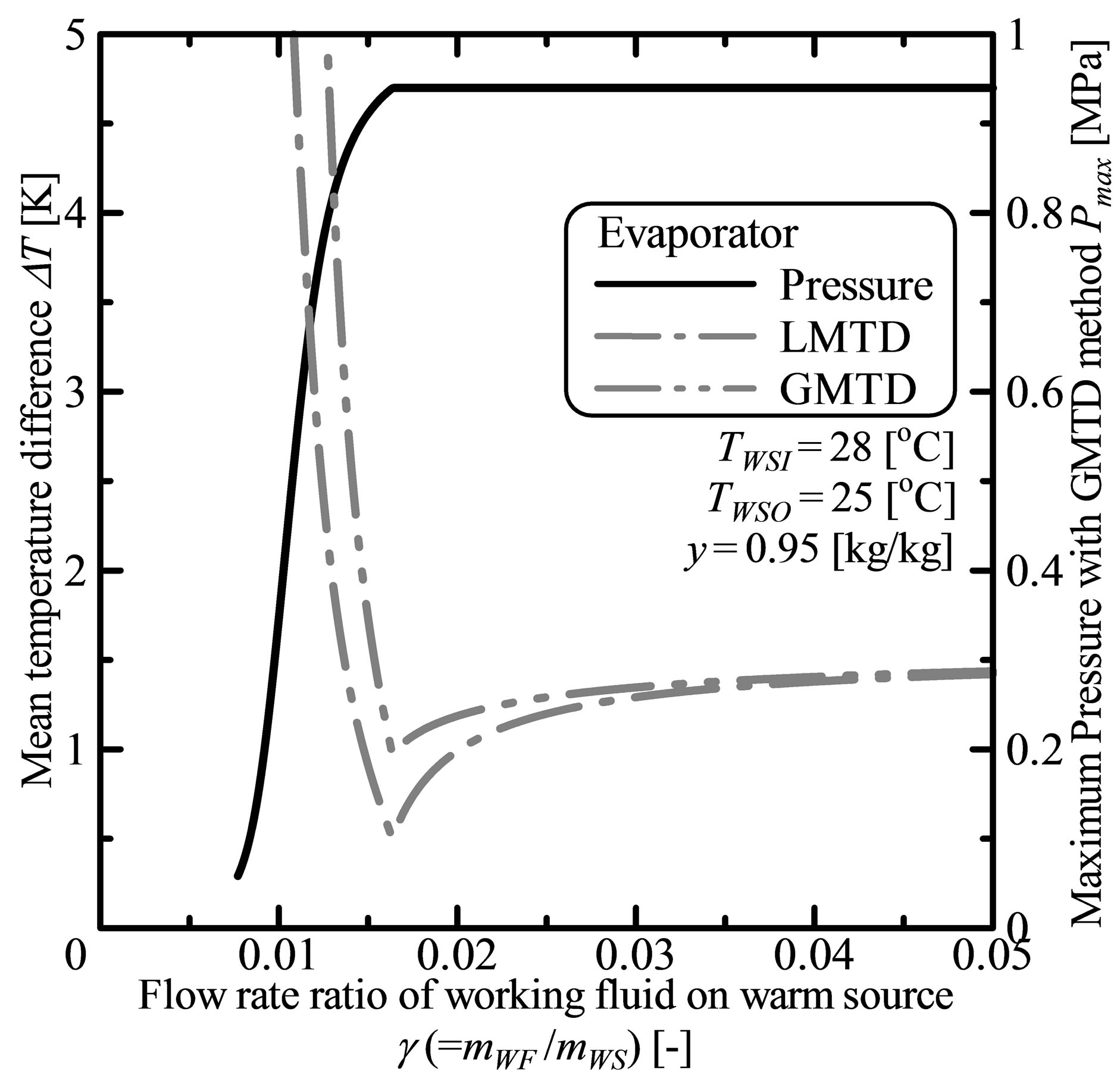
Figure 4(a) shows the mean temperature difference between ammonia/water mixture and warm water from the LMTD and GMTD methods and the evaporation pressure PE of the working fluid, in the evaporator with the massflow-rate ratio of working fluid to warm source. Here PE is defined as the maximum evaporation pressure of the working fluid, Pmax for these calculation settings. Figure 4(b) shows the mean temperature difference between the ammonia/water mixture and cold water for both LMTD and GMTD methods as well as the conden sation pressure of the working fluid, PC, in the condenser against the mass-flow-rate ratio of working fluid to cold source. The condensation pressure, PC is defined as the minimum condensation pressure of the working fluid, Pmin for these calculation settings. The same settings for the inlet and outlet temperatures for evaporator and condenser described in Section 3 apply here. The ammonia concentration in the mixture is 0.95 kg/kg; the mass-flow-rate ratio of working fluid to heat source, γ varied from 1.0 × 10⁻³ to 5.0 × 10⁻². The temperature difference at the pinchpoint is 0.5˚C. The working fluid is also assumed to be saturated liquid at the evaporator inlet and saturated vapor at the condenser outlet. The physical properties of ammonia/water mixture are evaluated using the M-PROPATH database [22].
The mean temperature difference is higher in the evaporator from the GMTD method than from the LMTD method at low flow-rate ratios (Figure 4(a)). The pinchpoint appears at the evaporator inlet and outlet, reflecting the convex downward nature of the variation of the working fluid temperature compared with the warm water temperature. The convexity of the working fluid temperature changes strongly when the temperature difference of the working fluid between the evaporator inlet and outlet increases. The maximum pressure decreases with decreasing mass-flow-rate ratio at low flow-rate ratio, that is, 1.64 × 10⁻² or less under these calculation conditions, because of the increasing working fluid temperature difference between evaporator inlet and outlet. In contrast, the mean temperature differences from GMTD and LMTD methods are almost equal at the high flow-rate ratios. The convexity of the working fluid temperature is not strong at the high flow rate ratio, that is, 5.0 × 10⁻² or more under these calculation settings, because the working fluid temperature difference between evaporator inlet and outlet is small.
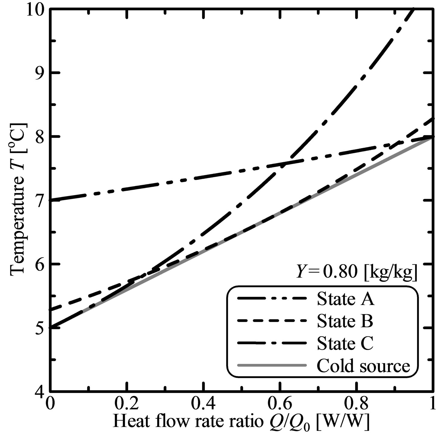
Figures 5(a) and (b) shows an example where there are variations in the working fluid and warm water temperatures in the evaporator at heat-flow-rate ratio of 0.80 kg/kg and 0.95 kg/kg ammonia concentration, respectively, and the temperature difference at the pinch-point is 0 K. The working fluid temperature curve against heat flow rate is convex downward. Its slope rises gradually as the ammonia concentration in the mixture increases. The path between the working fluid outlet temperature and warm source inlet temperature is defined as “State A”. The mass-flow-rate ratio for “State A” is under 1.64
 (a)
(a)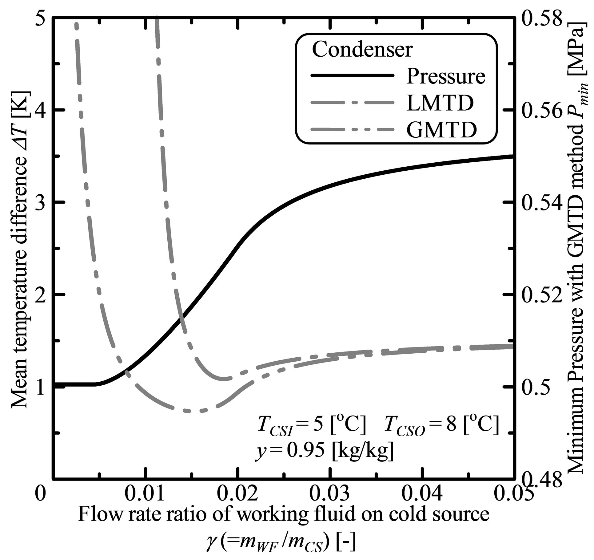 (b)
(b)
Figure 4. Temperature change in heat exchangers. (a) Evaporator; (b) Condenser.
 (a)
(a) (b)
(b)
Figure 5. Temperature change in the evaporator. (a) Y = 0.80 kg/kg; (b) Y = 0.95 kg/kg.
× 10−2. A similar path at the evaporator inlet and outlet, defined as “State B”, has mass-flow-rate ratio of 1.64 × 10⁻², and the mean temperature differences from the GMTD and LMTD methods are minimal. The path between the working fluid inlet temperature and warm source outlet temperature is defined as “State C”. The variation in the maximum pressure is constant because at evaporator inlet the working fluid is saturated liquid. The mass-flow-rate ratio for “State C” exceeds 1.64 × 10⁻².
The mean temperature difference is lower from the GMTD method than from the LMTD method at low flow-rate ratios in the condenser (Figure 4(b)). For the condenser, the working fluid is high temperature fluid, and the cold water is low temperature fluid. A pinchpoint appears as a consequence of convex downward variation in the working fluid temperature compared with that for the cold water temperature. Similar to the convexity in the working fluid temperature in the evaporator, the temperature in the condenser changes when the temperature difference of the working fluid between the condenser inlet and outlet increases. Therefore, the minimum pressure decreases gradually with decreasing mass-flowrate ratio. The mean temperature differences from the GMTD and LMTD methods are almost equal at highflow-rate ratios, that is, 5.0 × 10⁻² or more with these calculation settings, because the working fluid temperature difference between evaporator inlet and outlet is small.
Figures 6(a) and (b) show as a further example with property variations in the working fluid, the cold water temperatures in the condenser against heat-flow-rate ratio at ammonia concentration of 0.80 kg/kg and 0.95 kg/kg, respectively, when the temperature difference of the pinch-point is 0 K. The path between the working fluid outlet temperature and cold source inlet temperature is defined as “State A”. The variation of the minimum pressure is constant from the assumption that the working fluid is saturated liquid at the condenser outlet. The mass-flow-rate ratio for “State A” is 4.4 × 10⁻³ or less. Similarly, the path between the working fluid outlet temperature and warm source temperature in the condenser is defined as “State B”. The pinch-point for “State B” is transferred from the cold water condenser outlet to the inlet when the mass-flow-rate ratio decreases. The mass-flow-rate ratio for “State B” is from 4.5 × 10⁻³ to 1.96 × 10⁻². The mean temperature difference from the GMTD method is a minimum when the mass-flow-rate ratio is 1.53 × 10⁻², but the minimum from the LMTD method occurs when the mass-flow-rate ratio is 1.85 × 10⁻². The path between the working fluid inlet temperature and warm source outlet temperature is defined as “State C”. From the GMTD method, the mean temperature difference is lower for “State B” in the condenser. The mass-flow-rate ratio for “State C” is 1.97 × 10⁻² or more.
5. Ammonia Concentration and Cold Source Temperature Dependencies from GMTD and LMTD Models
Obtained using the GMTD method, Figures 7(a) and (b)
show the dependence of the maximum pressure in the evaporator on the mass-flow-rate ratio of working fluid to warm source. Similarly, Figures 8(a) and (b) show the dependence of minimum pressures for the condenser on the mass-flow-rate ratio of working fluid to cold source. The same calculation settings as describe above in Section 3 are used. The mass-flow-rate ratio of the working fluid with heat source varied from 1.0 × 10⁻³ to 5.0 × 10⁻². Again, the working fluid is saturated liquid at the evaporator inlet and saturated vapor at the condenser outlet. The physical properties of ammonia/water mixture are evaluated using the M-PROPATH database [8]. The ammonia concentration in the mixture varied from 0.99 to 0.80 kg/kg in Figures 7(a) and 8(a). The warm water temperature at the evaporator outlet varied from 27˚C to 24˚C in Figure 7" target="_self"> Figure 7(b). The cold water temperature at the condenser outlet varied from 6˚C to 9˚C in Figure 8(b).
The convexity of the working fluid temperature changes strongly when the ammonia concentration in the mixture increases (Figures 5(a) and (b)). For “State A”, the maximum pressure decreases gradually at low ammonia concentrations compared with high ammonia concentrations as mass-flow-rate ratio decreases. In contrast, the mass-flow-rate ratio for “State B” increases with increasing warm water temperature difference between evaporator inlet and outlet.
Like convexity for the working fluid temperature in the evaporator, that in the condenser changes when the ammonia concentration in the mixture increases, (Figures 6(a) and (b)). Therefore, the mass-flow-rate ratio for “State B” increases with decreasing ammonia concentration. The slope of the cold water temperature curve is steep when the cold water temperature difference between the condenser inlet and outlet increases. The range for “State B” increases as the cold water temperature difference increases because the pinch-point at “State B”
 (a)
(a) (b)
(b)
Figure 6. Temperature change in the condenser. (a) Y = 0.80 kg/kg; (b) Y = 0.95 kg/kg.
 (a)
(a) (b)
(b)
Figure 7. Maximum evaporation pressure. (a) Ammonia concentration; (b) Warm source outlet temperature.
 (a)
(a) (b)
(b)
Figure 8. Maximum condensation pressure. (a) Ammonia concentration; (b) Cold source outlet temperature.
is transferred from the cold water condenser outlet to the inlet.
The correlation between the mean temperature differences from both GMTD and LMTD methods plotted in Figures 7(a) and 8(a) is presented in Figure 9; the broken line refers to an ammonia concentration of 0.99 kg/kg, the chain line to 0.90 kg/kg, and the two-dot chain line to 0.80 kg/kg; the circles refers to a mass-flow-rate ratio of 5.0 × 10⁻², the black circle 3.0 × 10⁻², and the rectangle 2.0 × 10⁻². The convexity of the working fluid temperature changes strongly when ammonia concentration in the mixture increases (Figures 5 and 6). Therefore, the mean temperature difference differs between the GMTD and LMTD methods when the ammonia concentration in the mixture increases.
6. Conclusions
To obtain reliable data on the characteristics of a heat exchanger that uses ammonia/water mixture as working fluid, the recently developed GMTD method, which is to replace the traditional LMTD method, was assessed for validity in application. The conclusions are as follows:
1) Mean temperature differences between pure ammonia and water obtained with the LMTD and GMTD methods are almost equal. In contrast, the evaluation of

Figure 9. Relationship between GMTD and LMTD.
heat exchange using ammonia/water mixtures using the LMTD method was unsatisfactory. Temperatures in the ammonia/water mixture differ from warm water temperatures in the evaporator, and only approach cold water temperatures in the condenser.
2) Mean temperature differences are higher in the evaporator and lower in the condenser from the GMTD method than from the LMTD method, because the convexity of ammonia/water mixture temperature changes strongly as ammonia concentration increases. From the GMTD method, the mean temperature difference is lower when the working fluid temperature approaches the cold water temperature in the condenser.
3) For “State A”, the maximum pressure in the evaporator decreases with decreasing mass-flow-rate ratio of ammonia/water mixture to water, owing to an increase in the temperature difference between the evaporator inlet and outlet. In contrast, the variation in the maximum pressure is constant at “State C” because the working fluid is assumed to be saturated liquid at evaporator inlet. The maximum pressure decreases with decreasing ammonia concentration in the mixture.
4) The variation in the minimum pressure in the condenser is constant assuming that the working fluid at condenser outlet is saturated liquid. The pinch-point for “State B” is transferred from the cold water condenser outlet to the inlet as the mass-flow-rate ratio decreases. Therefore, the minimum pressure for “State B” decreases with decreasing mass-flow-rate ratio. At low mass-flowrate ratios, the minimum pressure for “State C” decreases gradually with decreasing the mass-flow-rate ratio that reflects the convex downward behavior of the working fluid temperature compared with the cold water temperature. The slope of the cold water temperature is steep when the cold water temperature difference between the condenser inlet and outlet increases. The range of “State B” increases with increasing the cold water temperature difference because the pinch-point for “State B” is transferred from the cold water condenser outlet to inlet.
Hence, the GMTD method can be applied to cycle calculations of power plants and refrigeration systems using ammonia/water mixture. Further research into compatibility conditions and accuracy of the GMTD method will be carried out.
REFERENCES
- A. H. A. William and W. Chih, “Renewable Energy from the Ocean: A Guide to OTEC,” Oxford University Press, New York, 1994.
- Y. Ikegami and H. Uehara, “Conceptual Design of Ocean Thermal Energy Conversion (OTEC) Power Plants in Sri Lanka,” Proceedings of the 8th International Society of Offshore and Polar Engineers, 1998, pp. 140-148.
- Y. Ikegami and H. Uehara, “Optimum Design Point for a Closed-Cycle OTEC System,” Proceedings of the 4th International Society of Offshore and Polar Engineers, 1994, pp. 383-389.
- F. Sun, Y. Ikegami, B. Jia and H. Arima, “Optimization Design and Exergy Analysis of Organic Rankine Cycle in Ocean Thermal Energy Conversion,” Applied Ocean Research, Vol. 35, 1994, pp. 383-389.
- N. Yamada, A. Hoshi and Y. Ikegami, “Performance Simulation of Solar-Boosted Ocean Thermal Energy Conversion Plant,” Renewable Energy, Vol. 34, No. 7, 2009, pp. 1752-1758. http://dx.doi.org/10.1016/j.renene.2008.12.028
- F. Sun, Y. Ikegami and B. Jia, “A Serformance Simulation of Solar-Boosted Ocean Thermal Energy Conversion Plant,” Renewable Energy, Vol. 41, 2012, pp. 220-219.
- A. I. Kalina, “Generation of Energy by Means of a Working Fluid, and Regeneration of a Working Fluid,” United States Patent 4346561, 1982.
- H. Uehara and Y. Ikegami, “Parametric Performance Analysis of Otec Using Kalina Cycle,” ASME, 1993, pp. 203-207.
- H. Uehara, Y. Ikegami and T. Nishida, “Performance Analysis of OTEC System Using a Cycle with Absorption and Extraction Processes,” Transactions of the Japan Society of Mechanical Engineers, Series B, 64-624, 1998, pp. 384-389.
- G. Wall, C. C. Chuang and M. Ishida, “Exergy Study of the Kalina Cycle,” American Society of Mechanical Engineers (ASME), 10-15, 1989.
- Y. M. El-Sayed and M. A. Tribud, “Theoretical Comparison of the Rankine and Kalina cycles,” ASME Publication, 1, 1985, pp. 97-102.
- V. P. Pall and L. Eliasson, “Factors Influencing the Economics of the Kalina Power Cycle and Situations of Superior Performance,” International Geothermal Conference, 2003, pp. 32-40.
- M. D. Mirolli, “Cementing Kalina Cycle Effectiveness, the Kalina Cycle for Cement Kiln Waste-Heat-Recovery Power Plants,” IEEE Industry Applications Magazine, Vol. 12, No. 4, 2006, pp. 60-64. http://dx.doi.org/10.1109/MIA.2006.1678332
- U. R. Nasruddin, M. Rifaldi and A. Noor, “Energy and Exergy Analysis of Kalina Cycle System (KCS) 34 with Mass Fraction Ammonia-Water Mixture Variation,” Mechnical Science and Technology, Vol. 23, No. 7, 2009, pp. 1871-1876. http://dx.doi.org/10.1007/s12206-009-0617-8
- Z. Guzovic, D. Loncar and N. Ferdelji, “Possibilities of Electricity Generation in the Republic of Croatia by Means of Geothermal Energy,” Energy, Vol. 35, No. 8, 2010, pp. 3429-3440. http://dx.doi.org/10.1016/j.energy.2010.04.036
- K. E. Starling, D. W. Johnson, H. Hafezzadeh, L. W. Fish, H. H. West and K. Iqbal, “Use of Mixtures as Working Fluids in Ocean Thermal Energy Conversion Cycles— Phase I,” US DOE Report, 1974.
- K. E. Starling, D. W. Johnson, H. Hafezzadeh, L. W. Fish, H. H. West and K. Iqbal, “Use of Mixtures as Working Fluids in Ocean Thermal Energy Conversion Cycles— Phase II,” US DOE Report, 1978.
- C. B. Panchal, D. L. Hillis, J. J. Lorenz and D. T. Yung, “OTEC Performance Tests of the Trane Plate-Fin Heat Exchanger,” Ocean Thermal Energy Conversion Program Argonne National Laboratory, 1981.
- Y. Ikegami, H. Goto, T. Morisaki and T. Furukawa, “Effect of Working Fluid Flow Rate and Ammonia Concentration on OTEC Using Ammonia/Water Mixture as Working Fluid,” 13th Asian Congress of Fluid Mechanics, 2010, pp. 1026-1029.
- Y. Ikegami, K. Urata, J. Inadomi, H. Goto, T. Morisaki, K. Inoue and S. Goto, “Investigation on the Stability of OTEC System Using Ammonia/Water Mixture as Working Fluid by Continuous Operation for Two Weeks,” Proceedings of the 20th International Society of Offshore and Polar Engineers, 2010.
- M. Utamura, K. Nikitin and Y. Kato, “Generalization of Logarithmic Mean Temperature Difference Method for Heat Exchanger Performance Analysis,” Thermal Science & Engineering, Vol. 15, No. 3, 2007, pp. 163-172.
- PROPATH Group, “A Program Package of ThermoPhysical Properties of Fluids, Version 11.1,” PROPATH Group.