Impact of Parasitic Resistances on the Output Power of a Parallel Vertical Junction Silicon Solar Cell ()
Received 16 November 2015; accepted 13 March 2016; published 16 March 2016

1. Introduction
The depletion of fossil energy sources and the heavy pollution of the atmosphere push the researchers to find an alternative such as solar energy obtained by using solar panels. The strong demand for solar power requires a deep research to increase the efficiency of solar panels. It is therefore urgent for us to find anything that may weaken the smooth functioning of the panels. The performance of these panels can be known and improved by the study of certain electrical parameters such as parasitic resistances. These parameters are derived from the junction non-ideality, volume carriers recombination, current leakages, and, on the other hand, the material resistivity, metallic contacts and collection grids [1] [2] . The aim of this work is two-fold: to show an analytical approach of the measurement of parasitic resistances and their impact on the performance of the solar cell.
2. Theoretical Background
The parallel vertical junction silicon solar cell is presented in Figure 1 [3] .
We assume that illumination is made with polychromatic light, and is considered to be uniform on the z = 0 plane. The contribution of the emitter is neglected.
When the solar cell is illuminated, there are simultaneously three major phenomena that happen: generation, diffusion and recombination.
These phenomena are described by the diffusion-recombination equation obtained with [3] [4] :
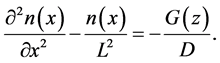 (1)
(1)
D is the diffusion constant:
 (2)
(2)
With q as the elementary charge, k the Boltzmann constant; T is the average temperature prevailing in the material.
G(z) is the carrier generation rate at the depth z in the base and can be written as [5] [6] :
 (3)
(3)
ai and bi are obtained from the tabulated values of AM1.5 solar illumination spectrum. n(x), L, t, and μ are respectively the density of the excess minority carriers, the diffusion length, lifetime and mobility.
The solution to the Equation (1) is:
 (4)
(4)
Coefficients q1 and q2 are determined through the following boundary conditions [7] :
・ at the Junction (x = 0):
![]()
Figure 1. Vertical parallel junction solar cell (H = 0.02 cm; W = 0.03 cm).
 (5)
(5)
This boundary condition introduces a parameter Sf which is called recombination velocity at the junction.
・ in the middle of the base (x = W/2):
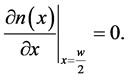 (6)
(6)
The photocurrent Jph is obtained from the following relation [8] [9] :
 (7)
(7)
The photo-voltage given by [8] [9] :
 (8)
(8)
with
 (9)
(9)
ni refers to the intrinsic concentration of minority carriers in the base [10] .
An is a specific constant of the material (An = 3.87 × 10¹⁶ for silicon), Eg is the energy gap and NB is the base doping rate.
The current-voltage characteristic is illustrated by the Figure 2 below.
This characteristic presents two very significant zones:
Area 1 is called the short-circuit operation point vicinity. The current-voltage characteristic in this area is illustrated by Figure 3.
It can be noticed that the current-voltage characteristic at the vicinity of the short-circuit operation point is a straight line:
 (10)
(10)
![]()
Figure 2. Current-voltage characteristic (z = 10−3 cm).
with
Jsc: short-circuit current density.
Rsh is internal resistance, called shunt resistance.
From the Equation (10), the expression of Rsh is:
 (11)
(11)
Area 2 of Figure 2 is called the open-circuit operation point vicinity. The corresponding characteristic is illustrated by Figure 4 below.
The current-voltage characteristic at the vicinity of the open-circuit operation point is a straight line:
 (12)
(12)
![]()
Figure 3. Current-voltage characteristic at the vicinity of the short-circuit operation point (z = 10−3 cm).
![]()
Figure 4. Current-voltage characteristic at the vicinity of the open-circuit operation point (z = 10−3 cm).
with
Rs: is internal resistance, called series resistance.
Voc: open-circuit photovoltage.
From the equation (12) the expression of the series resistance is:
![]() (13)
(13)
The effects of these resistances are noticeable when the solar cell operates in one of the follow cases: in a short-circuit situation, Rs is negligible as compared to Rsh; and in an open-circuit situation Rsh is negligible in return [11] .
3. Results and Discussion
This section is concerned with the profile of electrical power regarding parasitic resistances.
Figure 5 illustrates the profile of the output power regarding the shunt resistance.
It can be noticed that power increases along with shunt resistance (Rsh). The values taken by Rsh are high as shows it the scientific literature [12] .
Indeed shunt resistance (Rsh) is an internal resistance that is maintained by the solar cell to be opposed to the current leakage around the junction. Rsh also explains the volume and surface recombination of carriers. Rsh is said to be high when several electrons cross the junction to be collected as photocurrent [12] .
Thus volume and surface recombination and current leakage are all the lower as Rsh is high. Consequently the solar cell is powerful when shunt resistance is high as the curve in Figure 5 shows.
The profile of the output power regarding the series resistance is illustrated by Figure 6.
It can be noticed that an increase in the series resistance causes decrease in the output power. The values taken by Rs are low. But they are in agreement with those which one finds in the scientific literature [12] .
The series resistance (Rs) comes from the resistivity of the material used, from the metallic contacts and the collection grid. It also should be added that Rs emerges in a context of opposition to the diffusion of charge carriers to be collected as output-current at the junction. This same observation was also said in the scientific literature [2] where we learn that, when the output current increases the PN junction behaves as a resistance to oppose current.
High Rs decreases the flow of electrons which cross the junction. Consequently the solar cell is all the more powerful as Rs is low.
![]()
Figure 5. Electric output power versus shunt resistance (z = 10−3 cm).
![]()
Figure 6. Electric output power versus series resistance (z = 10−3 cm).
4. Conclusions
Through an analytical approach, the present work has allowed a measurement of the parasitic resistances (series and shunt resistances) of a vertical junction solar cell. This approach relies on linearalization of the curve through the short-circuit and open-circuit areas. It has thus shown that a solar cell is powerful when the series resistance is low and shunt resistance is high.
This work can be deepened by making a detailed study on the impact of parasitic resistances on other electrical parameters such as photocurrent, photovoltage and the diffusion capacity of solar cells.