Dynamic Compressive Deformation and Fracture of a Hollow Bulk Metallic Glass ()
1. Introduction
Since the successful vitrification of liquid alloys by the rapid solidification in 1960, metallic glasses have received extensive interests [1]. As potential advanced structural materials, bulk metallic glasses (BMGs) have outstanding mechanical properties, such as a high strength of up to 5 GPa, [2] a large elastic deformation limit of around 2 %, as well as good fatigue properties. However, the poor ductility due to the highly-localized inhomogenous deformation and subsequent catastrophic fracture limit their processing and application severely.
Zr41.2Ti13.8Cu12.5Ni10.0Be22.5is one of the best glass formers developed in recent years [3-6]. However, like most other metallic glasses, it also fails catastrophic fracture, due to the excessive propagation of individual shear bands [7,8]. Various methods have been adopted to enhance the toughness of monolithic metallic glasses. For example, a large poisson ratio (υ), which can cause the tip of a shear band in BMGs to extend rather than initial a crack [9]. Deformation is accompanied by the formation of multiple shear bands, which results in an improved plasticity. Besides, it has been demonstrated that an exterior constraint is one of approaches for multiplying the shear bands and preventing the BMGs from the premature fracture [10]. Jiang et al. [11] have investigated the compressive deformation and fracture of hollow BMGs upon quasi-static compressive loading. The results show that the hollow Zr52.5Cu17.9Ni14.6Al10.0Ti5.0 (Vit 105) BMG has excellent plasticity by tailoring the stress distribution upon loading. It is obtained that the ductility of BMGs is highly related to different geometries of samples.
In actual engineering applications, most deformation and fracture occur under high-speed dynamic loading, such as defense, aerospace, precision machinery, automotive industries, and high-speed metal forming. However, the resistance to deformation or fracture under dynamic loading is generally lower than that under quasistatic loading, and the plastic deformation is often highly localized in a narrow region [12-16]. Therefore, it is required to obtain information on the dynamic deformation of BMGs so that it can be effectively applied to such strategic fields. Recently, Qiao et al. [17] investigated the dynamic compressive behaviors of Zr-based BMG composites, and found that multiple shear bands were not formed sufficiently under dynamic loading condition, thereby, leading to the lower maximum compressive stress than that measured under quasi-static loading condition. However, the deformation and fracture of hollow Zr-based BMGs under dynamic loading is not yet to be investigated. In this study, the dynamic loading to a hollow BMG will be studied.
2. Experimental
The Zr41.2Ti13.8Cu12.50Ni10.0Be22.5 BMGs in an atomic percent was prepared by arc-melting pure elements with purity higher than 99.9 wt% under highly pure argon atmosphere with titanium as a getter, followed by casting in a water-cooled copper mould, which exhibit high thermal conductivity. The resulting cylindrical BMG rods have a dimension of about 90 mm in length and 6 mm in diameter. The hollow specimens were prepared by drilling machine with an alloy-steel drill bit, and the diameter of drill bit is 2.5 mm. The amorphous nature was confirmed by high-energy X-ray diffraction. The as-cast specimens for dynamic compression tests have a dimension of 6 mm in diameter and 6 mm in height, with an aspect ratio of 1. The ends of the samples were well polished with 1500 grinding paper. The dynamic loading experiments were conducted at room temperature, using a SHPB apparatus, and the detailed process was described elsewhere [18,19]. A SHPB consists of two elastic pressure bars that sandwich the specimen between them, as shown in Figure 1. The striker bar is launched from a gas gun toward the input bar. The impact generates a compressive stress pulse in the incident bar. The stress wave travels toward the specimen, subjecting it to the required stress levels. A portion of the pulse is reflected back into the output bar. The incident and output bars are mounted with strain gages at midway points along the length of the bars to compare the strain signals associated with the waves as they pass by. Upon dynamic compressive loading, specimens were often crushed by the input bar. The fracture surfaces and the lateral surfaces of the deformed samples were investigated to identify the fracture mechanism using scanning electron microscopy (SEM).
3. Results and Discussion
Figure 2 shows the synchrotron high-energy X-ray profile of the Zr41.2Ti13.8Cu12.5Ni10.0Be22.5 BMGs, together with its corresponding to diffraction pattern (Figure 2 inset). Both indicate a typical amorphous structure for the present Zr-based BMGs, which identifies that no partial crystallization occurred. Thus the effect of crystallization on the mechanical behavior can be excluded.
Figure 3(a) displays the engineering stress-strain curve of the solid Zr41.2Ti13.8Cu12.5Ni10.0Be22.5 BMG upon dynamic compressive loading with the strain rate of 2.0 × 10³ s−1. It can be seen that the solid Zr-based BMG does not exhibit obvious yielding, which suggests this solid

Figure 1. Schematic of the split Hopkinson pressure bar (SHPB).
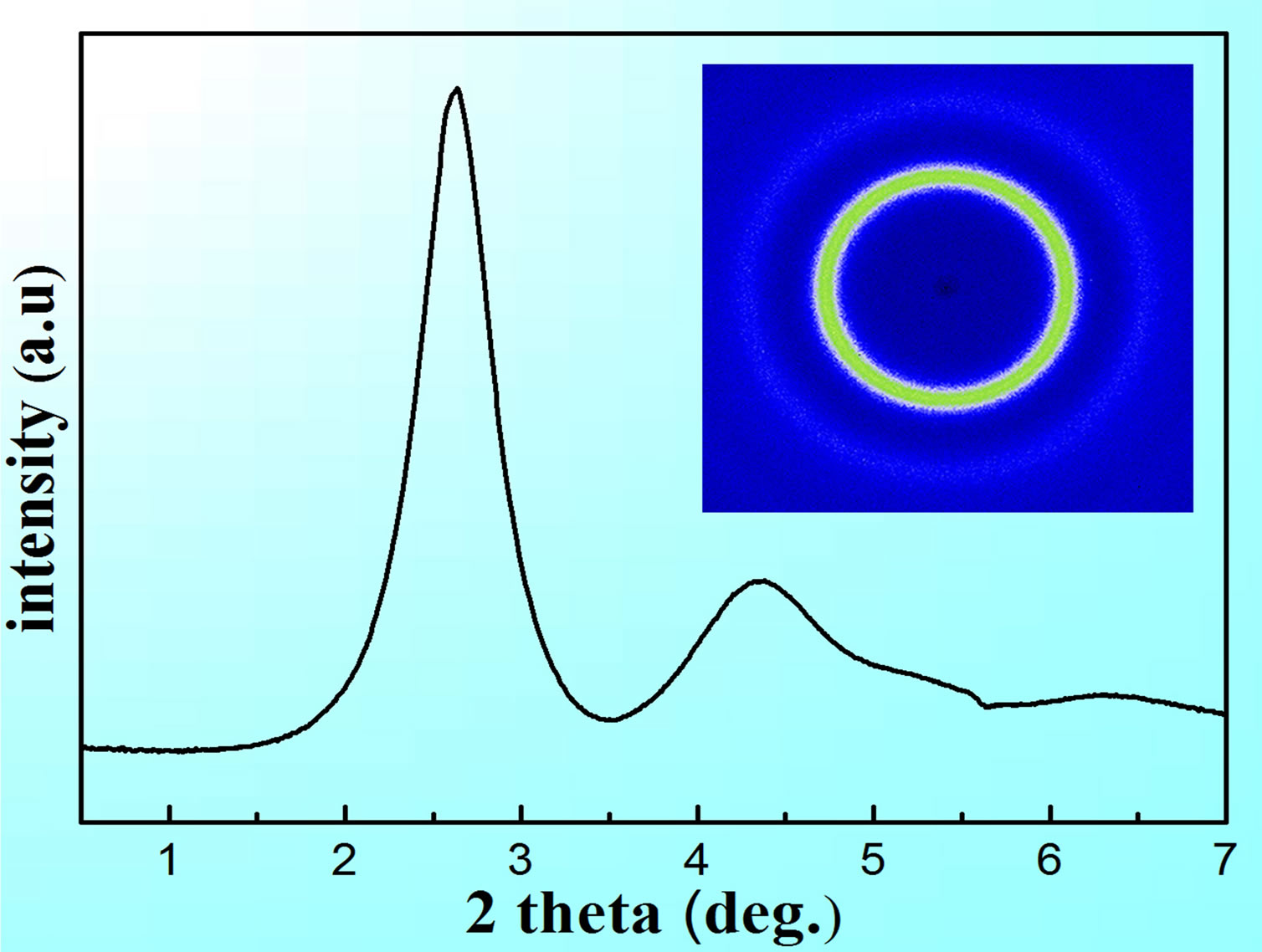
Figure 2. High-energy synchrotron XRD pattern of Zr41.2Ti13.8Cu12.5Ni10.0Be22.5 BMGs. Note that the inset is the diffraction pattern of Zr41.2Ti13.8Cu12.5Ni10.0Be22.5.
one without obvious plastic deformation, and its fracture strength approaches 1630 MPa. Kim et al. [20] have demonstrated that the solid cylindrical Zr41.2Ti13.8Cu12.5Ni10.0Be22.5 BMG’s fracture strength is 1440 ± 67 MPa, consistent with the present result. And the fracture strain of solid Zr41.2Ti13.8Cu12.5Ni10.0Be22.5 BMG is 1.7%. Jiang et al. have indicated that the fracture strength of solid Zr52.5Cu17.9Ni14.6Al10.0Ti5.0 BMG is 1920 MPa upon quasi-static loading, [11] together with poor ductility, which suggests monolithic BMGs have brittle fracture behavior, regardless of under dynamic or quasi-static compressive loading. It should be noted that the solid specimen’s elastic deformation stage is not a smooth straight line, indicating that the strain rate is not constant during dynamic compressive process but a mean value.
Figure 3(b) presents the engineering stress-strain curve of the hollow Zr41.2Ti13.8Cu12.5Ni10.0Be22.5 BMG upon dynamic compressive loading with the strain rate of 2.0 × 10³ s−1. The brittle fracture behaviors are similar to that of the solid one, and its fracture strength is 933 MPa, greatly lower than that of the solid one. The lowing strength for hollow ones has been indicated previously [11]. Compared to the solid one, the hollow specimen exhibits a lower fracture strength. From this curve, it can be seen that the hollow sample has brittle fracture without obvious plasticity upon dynamic loading. But Jiang et al. have reported that the Zr-based hollow specimen exhibits higher plasticity upon quasi-static loading, and the

Figure 3. The engineering stress-strain curves of the (a) solid and (b) hollow Zr41.2Ti13.8Cu12.5Ni10.0Be22.5BMGs upon dynamic compressive loading at the strain rate of 2.0 × 10³s−1; and (c) hollow Zr41.2Ti13.8Cu12.5Ni10.0Be22.5 BMG upon dynamic compressive loading at the strain rate of 1.0 × 10³s−1. The inset in (a) and (b) are the solid and hollow Zr41.2Ti13.8Cu12.5Ni10.0Be22.5 samples.
plastic strain of the hollow portion is as high as 43.7% before the final failure [11]. It is probable that the result is related to combined actions of the applied strain rate, the compression speed, and the propagating speed of the shear bands [21-27]. It follows that BMGs exhibit brittle behavior upon dynamic loading, even if hollow ones exhibit improved plasticity upon quasi-static loading [28].
Figure 3(c) displays engineering stress-strain curve of the hollow Zr41.2Ti13.8Cu12.5Ni10.0Be22.5 BMG upon dynamic compressive loading with the strain rate of 1.0 × 10³ s−1. It shows an initial elastic deformation, and then a platform is approaching, which indicates a certain plasticity. Finally, another elastic deformation occurs before ultimate fracture, and the slopes of these two elastic deformation portions in the stress-strain curves are approximately equal. Therefore, this shearing process of the hollow specimen can be divided into 3 stages, as shown in Figure 4(a), schematically. Firstly, the wall of specimen (red area) is sheared. Secondly, the hollow potion (yellow area) is sheared. In this stage, the hollow potion could be assumed be made up of a very ‘ductile’ phaseair. As far as this Zr-based BMG/air composite is concerned, the mechanical behavior is dominated by the deformation of the Zr-based amorphous phase and the special ‘ductile’ phase. When this ‘ductile’ phase is sheared, the stress is released instantaneously, and the strain energy is dissipated. In addition, the stress concentration is introduced in the hollow specimen under dynamic loading. In other words, inhomogenous stress distribution contributes to the generation of a certain plasticity. That is why there exists a platform on the stress-strain curve, which is similar to shear hysteresis phenomenon. Thirdly, the side wall of specimen (green area) is sheared. That means the first and third stages are the similar shearing process, which results in the equivalent slope of the two elastic deformation portions.
Compared to the hollow specimen at the stain rate of 1.0 × 10³ s−1, the hollow specimen at the stain rate of 2.0 × 10³ s−1 does not have a shear hysteresis. It seems to undergo one shearing process, as shown in Figure 4(b). To our knowledge, the strength of general ductile alloys are affected by the strain rate hardening, but this stain rate hardening is hardly expected in the hollow sample at the strain rate of 2.0 × 10³ s−1. It is explained that even though the plasticity of air is very large, a higher strain rate causes that it does not have sufficient time to occur up to the plastic region. Once initiated, the shear bands propagate, resulting in the prompt occurrence of shear failure. As a result, the plastic stain is not expected. Consequently, the sample exhibits brittle fracture. Different deformation and fracture mechanisms dominate the failure of the hollow specimens at different stain rate, resulting in the different mechanical performances.
At quasi-static loading, the geometrical constraint in the hollow BMG specimen can lead to the multiplication of shear bands, which moderates the localization of plastic deformation and delays the fracture. With the increase of strain rates, the increase of stress concentration is more and more severe. Figure 5 shows the finite-element modeling (FEM) to examine the stress distribution along the shearing plane with a 43 degree with respect to the loading direction. The external forcing is the same for the solid in Figure 5(a) and hollow one in Figure 5(b). It can be seen that the maximum stress concentrates at the center of the shearing plane for the solid Zr-based BMG. In contrast, for the hollow one, the high stress gradient is in the vicinity of the hole, and the stress concentration

Figure 4. The schematic shearing processes of the hollow Zr41.2Ti13.8Cu12.5Ni10.0Be22.5 specimens at the strain rate of (a)1.0 × 10³ s−1 and at the strain rate of (b) 2.0 × 10³ s−1.

Figure 5. The finite-element modeling (FEM) to examine the stress distribution along the shearing plane.
occurs near the hole. At the same external loading, the stress in the shearing plane of hollow ones is greatly higher than that of solid ones. As a result, an early failure happens with lower strengths for the hollow ones, in agreement with the experimental re sults.
Figure 6(a) shows the SEM image of the fracture surface of solid deformed specimen upon dynamic loading. The sample cracks into pieces after instantaneous destruction, as shown in the inset of Figure 6(a), caused by re-loading to the failure samples. It can be seen that typical vein patterns are distributed on the fracture surface, which has been widely observed in the fracture surfaces of other BMGs [29]. This phenomenon is very different from that under quasi-static loading, and the quasi-static fractured surface is almost covered by many liquid droplets and few vein patterns [30]. Upon quasistatic, the energy accumulated has sufficient time to be converted into heat, resulting in the temperature rise. So the vein patterns prevail on the dynamically fractured surface due to the insufficient temperature rise. When the bright dotted region in Figure 6(a) is magnified, a number of vein patterns are still observed, but tend to become more elongated, as shown in Figure 6(b). In addition, there are some resolidified liquid droplets (marked by the dark arrows) can be observed, which indicates that adiabatic heating occurs before yielding in this Zr41.2Ti13.8Cu12.5Ni10.0Be22.5 BMG. However, Bruck et al.

Figure 6. (a) Fracture surface of the solid BMG specimen and (b) enlarged images of the bright and dark dotted region in (a); (c) and (d) Fracture surface of the hollow BMG specimen. The inset in (a) and (c) are the images of solid and hollow fractured samples respectively.
observed the large temperature rise occurred before yielding in a Zr-based BMG upon dynamic compressive loading [31]. The difference may be related with different strain rates and chemical compositions [32,33]. The present experiment features the resolidified droplets, which suggests the temperature rise may be higher than the melting temperature at the moment of fracture upon dynamic loading. As a result, Zr-based amorphous phase only occurs localized melting with a relatively high strain rate, and the resolidified droplets can not cover the entire dynamically fractured surface, thus the vein patterns are still observed. When the dark dotted region in Figure 6(a) is magnified, besides vein patterns and resolidified droplets, a microcrack can be observed due to the severe deformation, as seen in the inset of Figure 6(b), consistent with recent theoretical and experimental studies [34,35]. It has demonstrated that the temperature rise in the narrow plastic zone, associated with a moving crack within the shear bands, can be as high as a few thousand Kelvin. This phenomenon can be explained with the energy conversion. Kinetic energy changes into heat and surface energy during this dynamic impact process. Just as some large cracks, they absorb much surface energy.
Figures 6(c) and (d) display the SEM micrographs of the broken hollow specimen surface upon dynamic loading. The sample cracks into pieces after instantaneous failure, as shown in the inset of Figure 6(c). Except for the elongated vein-like patterns, many fishbone-like patterns are observed on the fracture surface, marked by the dark arrows in Figure 6(c), and analogous result has been found in other BMGs [36]. It demonstrated that the fishbone-like patterns as well as the smooth regions between them indicate a lower crack propagation speed and a smaller temperature rise. Figure 6(d) shows some solidified liquid droplets (labeled by the dark arrows), which are distributed on the edges of veins, suggesting a significant temperature rise.
4. Conclusion After the text edit has been completed, the paper is ready The dynamic deformation behaviors of Zr41.25Ti13.75Cu12.50Ni10.00Be22.50 BMGs are investigated. The hollow and solid specimens’ deformation and fracture behaviors upon dynamic compressive loading are compared. They both exhibit little ductility, which are similar to other monolithic BMGs. Their fracture strengths are 1630 MPa and 933 MPa, respectively. It is obvious that the hollow one’s fracture strength is lower than that of the solid one, which is caused by the higher stress concentration for the hollow one through FEM modeling. The hollow specimens’ dynamic mechanical behaviors are very different from that upon quasi-static loading. The former exhibits poor plasticity, but the later exhibits large plasticity. The different strain-rate responses for the hollow Zr-based BMGs samples are compared and deeply explained. The vein patterns on the dynamically fractured surface are incompletely covered by the liquid drops, due to the insufficient temperature rise.
5. Acknowledgements
J.W.Q. and S.B.S. would like to acknowledge the financial support of National Natural Science Foundation of China (No.51101110, 51371122, and 51105267), the Youth Science Foundation of Shanxi Province, China (No.2012021018-1 and 2012021013-1), Research Project Supported by Shanxi Scholarship Council of China (No.2012-032 and 2012-030), and Supported by Program for the Outstanding Innovative Teams of Higher Learning Institutions of Shanxi (2013). Z.H.W. would like to acknowledge the Program for New Century Excellent Talents in University (NCET-10-0930).
NOTES