Broadband Miniaturized Bandpass Filter with Circular Stubs for Compact Wireless and Mobile Communication Systems ()
1. Introduction
Size reduction is an important issue in developing high performance miniature RF filters in wireless and mobile communication systems. The conventional edge parallelcoupled filter and hairpin filter are constructed in identical resonators cascaded in alternating series orientation which show steeper roll-off on the lower frequency side than on the higher frequency side [1-5]. Research on the modified miniaturized parallel-coupled filters has been reported to improve the filter’s symmetric response and upper stopband rejection characteristics [6-11]. In this paper, a new microstrip resonator filter with circular stubs is investigated for miniaturization and improvement in bandwidth. It is also known that the proposed filter geometries provide good upper stopband rejection characteristics. Analytical calculations and 3D electromagnetic simulations were carried out to determine the filter characteristics. Based on the design, a four-pole Chebyshev microstrip bandpass filter with circular stubs was fabricated and compared with design results.
2. Design of a Miniaturized Bandpass Filter with Circular Stubs
Miniaturization of filters can be explained as shown in Figure 1. It has been demonstrated that the conventional hairpin filters in Figure 1(a) can be miniaturized by a pair of coupled lines folded inside the resonator as shown in Figure 1(b). By utilizing the proposed filter in this work shown in Figure 1(c), one can achieve further miniaturization. This is due to the fact that the capacitance provided by the circular stubs decrease the resonant frequency. Figure 2 shows a typical resonator structure of the circular stub loaded bandpass filter. The resonator consists of a square ring with a pair of coupled lines folded inside the resonator which is connected to circular stubs. Compared to the conventional hairpin filters, the capacitance between both ends of the resonator allows miniaturization of the filter. The resonant frequency is reduced due to the shunt capacitance of the circular stub. Theoretical analysis on the radial stub loaded microstrip was reported [12-14]. The proposed structure can be analyzed as a capacitively loaded transmission line [15]. Figure 3 shows an equivalent circuit model for the proposed structure. A  is the total capacitance which
 (a) (b) (c)
Figure 1. Miniaturization of resonator filters: (a) Conventional hairpin resonator; (b) Square resonator with folded coupled line; and (c) Miniaturaized filter loaded with circular stubs.

Figure 2. Schematic of the miniaturized bandpass filter with circular stubs.
includes the circular stub mode capacitance of the foldedcoupled lines, and a fringing capacitance between openend circular stub and the adjacent microstrip line. The characteristic impedance, the propagation constant, and the resonator width are represented by  and
and , respectively. The resonant frequencies of the equivalent circuit can be obtained by applying the boundary conditions
  for a nontrivial solution of
  and
and  The resonant frequency can be obtained from [15, 16]
 (1)
(1)
where  is the center frequency,
  is the characteristic impedance of the stub, and
  is the electrical length.
Bandpass filters can be defined by three characteristics: resonator structure, coupling coefficients which are the coupling between resonators, and external quality factor which is the coupling to the terminations [17]. A four pole Chebyshev 0.01 dB bandpass filter was designed on a RT/Duroid substrate with a thickness of 0.635 mm and a relative dielectric constant of 10.2. For the center frequency of 1.56 GHz, bandwidth of 13% and an external quality factor,  of 5.5 were obtained. The coupling coefficients were K12 = 0.1407, K23 = 0.1034, K34 = 0.1407.

Figure 3. Equivalent circuit model for the miniaturized bandpass filter with circular stubs.
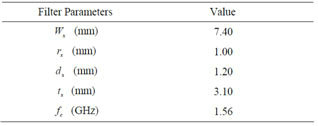
The fundamental resonance frequency depends on the dimensions of the connecting stub length and width, position of the circular stub connecting area, and number of stubs. Extensive 3D electromagnetic wave simulations were carried out using a 3D EM solver [18] in order to obtain the optimized parameters for the miniaturized bandpass filter with circular stubs. The optimized parameters are shown in Table 1. Figure 4 shows the filter simulated response for various values of the circular stub radius , the distance from the circular stub center to the line
 , and the circular position of the stub
 . The optimized structure which yields the widest bandwidth with steep filter roll-off characteristics shows
  of 7.4 mm,
  of 1.00 mm,
  of 1.20 mm, and
  of 3.10 mm. Figure 5 which shows external quality factor,
  for various values of
 ,
,  , and
, and . The optimized dimensions of
  of 1.00 mm,
  of 1.20 mm, and
  of 3.10 mm are indicated as minimum points in Figure 5 which implies that these dimensions provide the widest bandwidth.
3. Measurement Results and Discussion
A miniaturized bandpass filter with circular stubs was fabricated in the form of four identical resonators cascaded in alternating series orientation as shown in Figure 6. The substrate used was RT/d6010LM of Rogers Corporation. The  measurement results are compared in Figure 7 along with the simulated and the modified simulated results. The modified simulation curve was obtained using the actual fabricated circuit dimensions, dielectric constant, and conductor material. The measured passband loss was −3.4 dB at the midband which is caused by the dielectric loss of the substrate and conductor loss of the copper. The accuracy limitation in circuit fabrication using LPKF is believed to be the contributing factor for the bandwidth difference between simulated and measured results. Figure 8 shows the measured, simulated, and modified simulated results for
 . We have observed that as the width of the trace of the filter increases, the filter operating frequency increases, ripple decreases, and bandwidth increases. Compared to previously reported work on capacitively loaded parallel coupled bandpass filter [7,10,16-18], the proposed
Table 1. Optimized design parameters for the miniaturized bandpass filter with circular stubs.
filter provides 160% bandwidth improvement.
4. Conclusion
A square resonator bandpass filter with circular stubs is designed, fabricated, and characterized for miniaturization and bandwidth improvement. Based on the analytical calculations and 3D electromagnetic simulation, a four-pole Chebyshev microstrip bandpass filter was constructed with the substrate of RT/d6010LM from Rogers Corporation and was fabricated using LPKF Protomat machine. The measurement result was compared with the simulated and modified simulated results. The modified simulated curve was adjusted to the actual sizes of the

Figure 6. Photo of the fabricated four pole miniaturized bandpass filter with circular stubs.
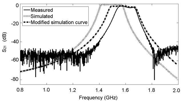
Figure 7. Comparison of simulated and measured  for the optimized miniaturized bandpass filter with circular stubs.

Figure 8. Comparison of simulated and measured  for the optimized miniaturized bandpass filter with circular stubs.
fabricated circuit, dielectric constant, and conductor material. The measured results were in good agreement with the designed results. The proposed filter is miniaturized in size compared to the conventional hairpin resonator and square resonator with folded coupled lines. Furthermore, it exhibits significant improvement in bandwidth compared to the conventional square resonator bandpass filters. The miniaturized bandpass filter with circular stubs can be potentially used for compact wireless and mobile communication systems.
5. Acknowledgements
The authors would like to thank Dr. Mark Wickert for his advice on circuit fabrication. We would also like to thank Tom Mulcahy and Dr. Jim Wigle for their technical support on LPKF Protomat.