Integrated Design Approach for Solving Complexity of Design Problem ()
1. Introduction
The nature of design is complex. Archer [1] wrote that “Design is that area of human experience, skill and knowledge which is concerned with man’s ability to mould his environment to suit his material and spiritual needs.” Nevertheless, design that relies on trial-and-error processes or empiricism based on human experiences and skills seems not adequate to solve today complexity. These experiences and knowledge must be improved by systematical approaches. To solve the complexity in design, replacing the empirical approach with a more scientific approach is preferable.
As today demands of quality, cost, time, and sustainability increase; the complexity in design raises rapidly. However, complexity could be solved if the design problems are structured. It requires experts from various disciplines to construct the design problems by providing the information, constraints, and knowledge. Yet, the experts must work collaboratively as a cross-functional team. To avoid the inter-disciplinary problems of design language (semantics), the design system must help support the designers to realize design solutions, information and constraints of each other.
This paper presents the integrated design system that is used to solve the complexity of multi-disciplinary design problems. Section 2 examines engineering design approaches that are used to deal with the design problems. The integrated design system follows those systematic approaches in order to construct an answer to the design problems. Section 3 presents the tools for solving the design problems by applying the concepts of ontology, multi-viewpoint, and knowledge management method. Section 4 presents a case study of furniture design using the integrate design system and a specific tool to solve the complexity of multi-disciplinary design. Finally, conclusion is given in Section 5.
2. Complexity in Engineering Design
In engineering design, it currently challenges designers to deliver the design that meet the customer’s requirements within a limited time and budget. This section reviews the development of engineering design approaches to represent how to construct the design problems and to solve the design complexity.
In a traditional design approach, designers work sequentially and independently on their tasks. It is considered as a time-consuming process. Then, Concurrent Engineering (CE) approach was introduced. It permits the designers to perform their tasks in parallel as a crossfunctional team and to deal with design problems of multiple decisions. However, since the system complexity increases, a number of decision increases as well. Any flaw decision will lead the system much more complex. At this time, collaborative approach is predominant in engineering design. As experts from each discipline mostly focus on their own objective, one objective may conflict with one’s others from different discipline. Collaborative engineering decreases space between design phases by increasing the degree of collaboration among individuals and teams with perspectives of negotiation and compromising to achieve a common goal.
Pahl et al. [2] state that “complexity” is one of a problem’s characteristic. Complexity is defined as many components are involved and these components, through links of different strength, influence each other. By complexity we mean that the transparency of the relationships between inputs and outputs is relatively poor, that the required physical processes are relatively intricate, and that the number of assemblies and components involved is relatively large. Lu and Suh [3] also states that complexity occurs in systems that have many elements with intricate dependencies among them. Due to their numerous sizes and relationships, the behaviors of complex systems are difficult to predict, even when the properties of their parts are given. Another characteristic of a problem is “uncertainty”. Uncertainty occurs when not all requirements are known; not all criteria are established; the effect of a partial solution on the overall solution or on other partial solutions is not fully understood, or only emerges gradually. The difficulties become more pronounced if the characteristics of the problem area change with time [2].
A systematic approach for engineering design is proposed in [2] in order to decreases the complexity of a technical system. This approach is to divide a technical system into sub-systems and elements. Then develop an interrelationship of the elements and represent as a structure. A complex system can be broken down into subfunctions of lower complexity. The combination of individual sub-functions results in a “function structure” representing the overall function of the technical system. Consequently, the divided sub-functions will be broken down into “working structure” that represents its physical processes. It determines geometric and material characteristics chosen that ensure the function is fulfilled. A working interrelationship established in the working structure leading to the construction structure. The construction structure takes into account the needs of production, assembly, transport, etc. It must satisfy the requirements of the selected working structure and any requirements necessary for the technical system. To fully identify these requirements, it is usually necessary to consider the system interrelationship. The overall interrelationship must be carefully considered during the development of the technical system. This approach can be summarized as shown in Table 1.
This approach decreases the complexity of a technical system by breaking down the system into elements. Then develop an interrelationship of the elements and represent as a structure of functions, working, and construction. Finally, combine those elements as a new system. This approach however does not indicate the dependency among elements (sub-functions and working principles) of the technical system. Therefore, it is quite difficult for the designer to recognize which design solutions have more or less complexity.
Quality Function Deployment (QFD) originated by Akao [4] is another well-known systematic approach for engineering product development. QFD helps support the designers to transform the voice of customer (customer needs) into engineering characteristics. It uses House of Quality (HOQ) diagram to represent a relationship matrix between WHATs (customer needs) and HOWs (how to satisfy the customer needs), a planning matrix, and a correlation matrix among HOWs. HOQ can be cascaded to get the information in different levels of the design process. It usually comprises of four levels: product planning, design deployment, process planning, and production operations planning. QFD method is intended to be used by cross-functional teams consisting of experts in several domains. As a result, QFD requires the significant resources to develop, populate, and analyze the results. A single design would require a large amount of time due to inter-disciplinary problems. In addition, lack of attention to the correlation matrix at the roof of the HOQ may lead the designers to waste amount of time in consequent cascades matrices. QFD indicates the correlation among HOWs. This correlation matrix conduces the designers know which HOWs reinforce or conflict to others. However, it does not notify how to reduce the design conflicts (negative correlations) that usually lead the complexity of a technical system.
To overcome the design conflicts occurred during the design process, TRIZ methodology is introduced to enhance QFD [5,6]. It provides a range of strategies and tools for finding inventive solutions that overcome the need for a trade-off between two HOWs. TRIZ however uses very abstract terms to express its theory and method and lacks math models and quantitative methodology to support its applications [7,8].
Table 1. Interrelationship in technical systems [2].

Lately, Axiomatic Design (AD) theory is proposed by Suh [9]. AD is a system design methodology that helps designers to structure design problems and provides theorems for solving complexity of technical system. In AD, there are four domains: customer, functional, physical, and process. These domains are mapped to one another in order to create design details in hierarchies of each domain. The design details represent a relationship between WHATs (what we want to achieve) and HOWs (how we choose to satisfy the need). It systematically transforms customer needs (CAs) into functional requirements (FRs), design parameters (DPs), and process variables (PVs). This decomposition technique is called zigzagging method. This systematic approach is similar to QFD method. However, AD uses matrices to define the design details. In addition, AD can assess the complexity of the design by two axioms i.e. Independence Axiom and Information Axiom.
The first axiom is to maintain the independence of the FRs. It notices the relationship between WHATs and HOWs by a design matrix that can be mathematically expressed in term of characteristic vectors as follows:
 (1)
(1)
where {FR} represents a set of FRs, {DP} represents a set of DPs, and [A] is a set of characteristics of the design that represents the relation between FRs and DPs, called “design matrix”. This design matrix implies the complexity of a system. A system can be either uncoupled design (diagonal matrix) or decoupled design (triangular matrix) or coupled design (full matrix) depending on the mutual dependencies of its elements in the design matrix. Thus, to maintain the independence of the FRs, the design matrix must be either diagonal or triangular. If the design matrix is not written in diagonal or triangular form, it must be reorganized as presented in [10-13].
The second axiom: Information Axiom is to minimize the information content of the design. A design is complex when its probability of success is low. In the other words, when the information content required to satisfy the FRs is high. The probability of success is governed by the intersection of the design range (dr) specified by the FRs and the system range (sr) that is proposed to satisfy the specified range, called common range (cr). In this axiom, information content (I) is defined as a logarithm function of design’s probability of achieving the specified FRs, area of common range (Acr) that can be written as:
 (2)
(2)
If the information content of the design is high, it leads the system to be complex. Suh describes the methods to minimize the information content of the design in his books [9,10].
The systematic approach proposed by Pahl et al. [2] provides the designers the procedural steps to design a technical system. QFD helps support the designers who are an expert in different domain to design the system as cross-functional teams. However, a collaboration of experts in different disciplines can result in multi-disciplinary design complexity. AD helps the design team to recognize the complexity of the system and provides the systematic methodology to solve such complexity. The next section presents the design tools that are used to solve the complexity of multi-disciplinary design problems.
3. Integrated Tools for Solving Complexity of Multi-Disciplinary Design
The nature of complexity of multi-disciplinary design requires experts from various disciplines to work collaboratively as a cross-functional team. Thus the design approach must be applied with flexibility and consideration of the knowledge and terminology of the various disciplines involved. It also should be able to provide the experts their own view in order to provide any information and knowledge of the design and share to common views if necessary. This section describes the tools used in the multi-disciplinary design process.
3.1. Data Model and Knowledge Model
To represent a system or a product, data model and knowledge model [14] are used in the design process. The data model consists of three types of object i.e. component, link, and relation, as shown in Figure 1. By the data model, experts from any discipline can structure the design of a system by decomposing it in hierarchies. The data model is used to represent elements in the system. However, it must be associated with the knowledge model in order to identify the characteristics and behavior of the elements.
Knowledge model allows the experts to define the elements created using their own semantics. It can be divided into two categories i.e. factual knowledge and temporal knowledge. Factual knowledge represents characteristics of “feature” associated to a component object, as shown in Figure 2. A feature “Shaft” is used to described the product from geometric viewpoint. It is associated by the “Link_1” (rad_1) to define that the characteristic “radius” is in “Equality” relation with another one. Values of characteristics of a feature can be affected by temporal knowledge represented by “production rules” [15]. A production rule governs the translation of semantics between disciplines. The instantiation of feature depends on the signification of sharing i.e. vernacular, vehicular, and universal [16]. Knowledge model is created
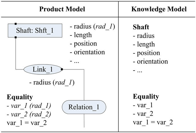
Figure 2. Data model associated with knowledge model.
based on ontology and can be enriched by interactions between the experts from various disciplines.
3.2. Multi-Disciplinary Concept
The integrated design system consists of different viewpoints depending on the intended purpose (number of joined disciplines). Based on the data model and the knowledge model, the designers can decompose the product in hierarchies and describe it by their own semantics. However, to support the experts from variousdisciplines to work collaboratively as a cross-functional team, some objects of the knowledge model created may need to be shared to other disciplines (vehicular feature) or to global (universal feature) if necessary.
By the help support of data model and knowledge model and multi-disciplinary concept, a product can be decomposed and represented into multi-viewpoint [17] as shown in Figure 3. The design system provides two types of viewpoint to the designers: trade view and common view. Each designer uses a trade view to describe the product in their specific viewpoint. Any universal feature created will be represented into the common view that consists of frame view and geometry view. Another important viewpoint in the design system is technologist view [18]. This view represents the functional interrelationship of the product as illustrated in Figure 4. It facilitates the designers to recognize the relationships between the design solutions proposed into the system.
3.3. Methods for Integration
Knowledge structure can be represented by relationships among theories. A theory can represent only a piece of knowledge about one discipline. Two theories should be in principle independent. If not, it means that the axioms of the two theories overlap each other. These interactions among theories are the source of complexity of multidisciplinary problems [19].
During the design process, an instantiation of feature represents an object of knowledge model. Each created instantiation should be independent to each other. If not, it means that there is a relationship to one another. In this case, when an expert creates an instantiation depending on his discipline, another instantiation is automatically engaged in the situation. As a result, this design could be
considered complex if the designers who are concerned to this information do not recognize it. Thus, any knowledge introduced into the design must be stored and can be shared if required. However, not any instantiation can be created. The designers must have a coincident notion of design, “just need concept” [20] as described below:
• Designer must provide information and constraints of the current design to the system as soon as possible.
• Such information must be justified. The designer must provide only justified constraints, not just because of personal preference.
With this notion, the designers have less contradiction during the design process. A knowledge module stores knowledge, both characteristics and constraints, provided by the various experts from joined disciplines. However, the difficulties still exist in the design process if such information and knowledge are not shared to the designers who are concerned.
Cooperative Design Modeler, CoDeMo [21], is the integrated design system presented in this paper. It is a client-server system that gives access to designers who work on the same project. It can overcome the difficulties of inter-disciplinary problems by using the methods of data propagation and data translation. These tasks are executed by the system agent who acts as an internal designer to help support the individuals to translate any semantics provided from one discipline and then propagate to other related disciplines.
With the notification function, any instantiation created into the design system by a designer in the client side will be mapped to the shared database of the server side as illustrated in Figure 5. As well as the creation, modification or deletion of any instantiation is also mapped to the shared database. This method creates a collaborative environment and enhances CoDeMo to be synchronous. However, if the created instantiation is vehicular or universal, it needs to be mapped to other view-

Figure 5. Architecture of data propagation.
points that are concerned.
The difficulties in collaboration of experts can result in three types: 1) ontology problem; 2) inherent difficulties in dealing with many stakeholders; and 3) multi-disciplinary design creates inter-disciplinary problems [19]. Since the designers use their semantics to describe the product, these semantics must be translated to any designers who are concerned with such information particularly that constrains other’s designs. The ontology problem can be reduced by using the data model and the knowledge model as described in 3.1. However, in certain situation, an instantiation created can induce other data. Then difficulties still exists as long as the stakeholders (designers) are not notified and up-to-date the current design information. To facilitate the designers in this case, knowledge modules and the method of data translation are necessary. Knowledge module allows the designers to gather knowledge and constraints in a specific grammar as shown, for example, in Figure 6. It is associated to the method of data translation that translates any features to other viewpoints that are concerned. According to Figure 6, once an instantiation of the feature “AxisSurface” is created in the Frame view, this feature is then translated to a feature “Cylinder” in the Geometry view. Indeed the “AxisSurface” represents actually a cylindrical functional surface. The associated shape is then a cylinder, as illustrated in Figure 7.
Though the data translation method can facilitate the designer to recognize the current design, it does not guarantee that design has not a conflict. In case that there is a design conflict, a compromise mechanism may have to be activated. Radulescu [22] enhances the knowledge module to be able to substitute a design conflict by the substitution method.
4. A Case Study
This section presents a case study of a furniture design process using CoDeMo as the integrated design system. At the initial phase of furniture design, the designer who concerns the global requirements, functionalities, and aesthetics of the product may propose a conceptual draft design to the system. This draft design can be handled by a CAD system and should be manipulated with the global requirements and functionalities. To facilitate the designers
| Component_Name AxisSurface Frame name |
| Translation Link name discipline axis_surface_name Component Cylinder Geometry name_Tran_0 Link name_Tran_0 surface_origin axis_geo_name Relation axis_surface_name name axis_geo_name name_Tran_0 Identity name_identity @ |
Figure 6. A knowledge module of for translation.