High Pressure Water-Jet Technology for the Surface Treatment of Al-Si Alloys and Repercussion on Tribological Properties ()
1. Introduction
In recent years, the use of high-pressure water jet technique became widely accepted practice in order to meet the requirements of production and maintenance. Water-jet technologies offer cleaning, machining, surface treatment and cutting of materials. Both roughening as well as polishing is possible with this procedure. It is therefore excellent for pre-treatment of engineering surfaces. For the last few decades, water-jet technology covered the following applications: removal of paint, grease, dirt from aircraft in the aviation industry; prevent pump cavitation; removal of cement lips, incrustations, lime, solidified dust from autoclave vessel; removal of worn protective coating, incrustations, solidified materials in the chemical industry; semiconductor frame cleaning in the electronic industry; removal of weld slag, water scale, mill scale and rust in steel mills; water jet cutting; vibration free demolition by abrasive water jets and so on [1-11].
The conventional water jet technique has been used for cutting and polishing by mixing abrasive materials into the water which transport the abrasive materials to strike the substrate. On the other hand, high pressure water jet can produce a compressed surface layer without abrasive materials, while the core of the component remains unchanged. The new surface layer “tribolayer” is expected to have enhanced tribological properties due to possible work hardening, residual stress and reduction of surface porosity. Hence, water jet treatment may be an effective technique for improved surface properties.
Aluminum-silicon based alloys have received considerable attention due to their high strength to weight ratio. The reduction in weight of components leads to significant impact on fuel economy in dynamic systems. In addition, these alloys are reported to have a reasonably high wear resistance. The wear resistance of Al-Si alloys depends on a number of material related parameters, i.e., size, shape, composition and distribution of micro-constituents, in addition to service conditions [12-16]. Porosity is a common feature of sintered Al-Si alloys and strongly influences their properties and applications. In general the presence of pores is accompanied by a drop in strength, ductility and wear resistance of materials [17]. Not only the total volume percentage of porosity influences the degradation of properties but also size, shape and interconnectivity of pores play an important role [18-20]. Meanwhile, initial attempts on the mechanical characterization of these materials were focused on static tests. However, in order to employ these materials in new applications, their dynamic properties have to be carefully assessed. In recent years, fatigue behavior has been studied in numerous investigations. The influence of pores on crack initiation and propagation under cyclic loading was examined as well [21,22]. The effect of water jet peening toward improving fatigue resistance was examined by various experimental tests and proved as an effective techniques for preventing fatigue in structural components [23-25].
The objective of this study is to assess the potential of employing high pressure water-jet technology for the surface treatment of Al-Si alloys to improve wear resistance for automobile and aerospace applications.
2. Experimental Details
In order to obtain a homogeneous distribution of porosity, samples were prepared using powder metallurgy method. Two powders (i.e., Al-Si master alloy and Al-Mg master alloy), were mixed to produce the following alloy composition; 88.8 wt% Al, 6.0 wt% Si, 4.5 wt% Cu, 0.5 wt% Zn, 0.2 wt% Fe. A Lico wax C was used as a pressing lubricant. Specimens were pressed at 100, 200 and 600 MPa and were sintered in a tube furnace in the presence of nitrogen gas at 5600 C for 20 minutes and then slow cool to 4800 C. The green and sintered densities of samples were determined in accordance with MPIF Standard 42 [26] and are listed in Table 1. For micro-structural experiments, specimens were cut, mounted and ground using 240, 320, 400 and 600 grit SiC abrasive papers and then polished using 1µm, 0.3µm and 0.05µm gama alumina suspension. Olympus BX51 research microscope, equipped with bright-field objectives was used to analyze the microstructure at high resolution.

Table 1. Basic properties of sintered Al - 6 wt% Si alloy.
Water-jet treatment was performed using a highly pressurized water-jet. The system is capable of employing ultrasonic pulses of water-jet for more intense treatment. Several tests were performed using the ultrasonic system. During experiments, specimens were individually mounted on a turntable inside the water jet enclosure. Specimens containing different amount of porosity (compacted at 100, 200 and 600 MPa) were subjected to water jet at four different pressures, 34, 48, 55 and 70 MPa, employing a nozzle with an orifice size of 1.6 mm. The standoff distances between the nozzle and the specimen were 25, 64, 76 mm and the translation speeds were 25, 50, 150 and 250 mm/s.
Surface porosities of samples were calculated using image analysis software. A series of images were taken to cover the whole surface area of the sample. Porosities were identified based on their gray-level intensity differences compared to the matrix. Gray-level threshold settings were selected to permit independent detection of porosity, using the “flicker method” of switching back and forth between porosity and the matrix. Second phase particles and dendrite, may be counted as porosity because their gray level range is similar to that of porosity. The grey-level thresholds as well as boundary conditions, (i.e., aspect ratio, min radius and area) were set to avoid second phase particles and dendrite. A counting protocol was chosen to correct for edge effects so that a porosity lying across a field boundary is counted only once [27]. For each field the area fraction of the detected area of porosity was measured by dividing the detected area of porosity by the area of the measurement field. Surface porosity values are given in Table 2.
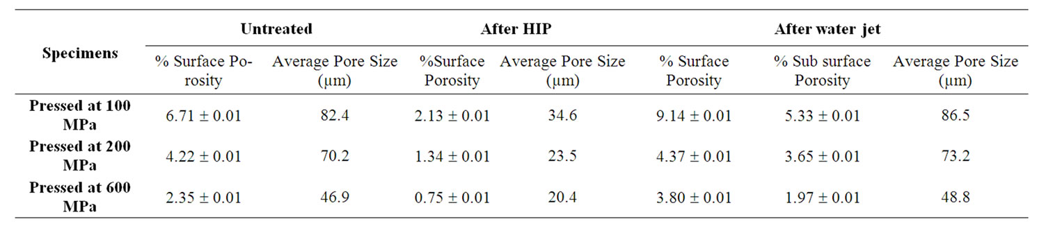
Table 2. Surface porosity of sintered Al-Si alloy.
Micromet micro-hardness tester was used to measure the micro-hardness of the specimens. This was conducted to assess the effect of water jet treatment on the sub-surface properties of the Al-Si alloy. In this test method, Vickers hardness measurements were performed using a diamond indenter and 15 g load. The size of the indentation was measured using a light microscope equipped with a filar type eyepiece. HV measurements were taken as a function of depth from the treated surface.
In order to measure residual stresses induced as a result of the high pressure water jet treatment, X-ray peak broadening diffraction techniques was employed. X-ray diffraction (XRD) experiment was carried out on a specimen treated ultrasonically at 48 MPa from 76 mm standoff distance and 150 mm/s translation speed, employing a high-speed Bruker D8 Advance system using Cu-Kα radiation having a wave length (λ) of 1.54 Å, tube voltage of 40 KV, and tube current of 40 mA. The strongest four peaks (i.e., (111), (200), (220) and (311)) were selected for slow scan of 0.02˚/sec. The integral breadth of XRD peaks were analysed using EVA software package. Peaks were corrected for the effects of Kα2 radiation and the background was removed. A standard stress-free Al from the same alloy was used to measure instrumental broadening. The data was treated according to Williamson-Hall method [28]. The integral breadth (i.e., total area under the peak/peak height) of the diffraction peak can be expressed as,
 (1)
(1)
Here Bsize and Bε are the grain size and micro-strain contributions to the observed peak broadening Bobs respectively. Bins is the peak broadening at a stress-free state, referring to the instrument contribution. The crystalline size “t” is related to Bsize by the Scherrer Equation [29],
 (2)
(2)
Here,  is Bragg’s angle. While the micro-strain can be calculated from,
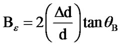 (3)
(3)
where, d is the interplaner spacing. Substituting Equation (2) and (3) into (1) gives,
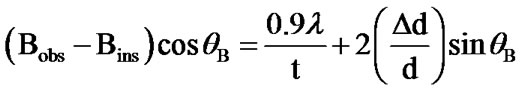 (4)
(4)
For grain size larger than 10 µm (as in the present case) X-ray peak broadening is due to micro-strain effect alone, hence, the first term in Equation (4) can be eliminated.
Dry reciprocating wear tests were performed using a Universal Micro-Tribometer. This test method utilizes a ball upper specimen that slides against a flat lower specimen in a linear, back and forth, sliding motion having a stroke length of 5.03 mm. All tests were conducted at room temperature and a relative humidity of 40% - 55%. The load is applied downward through the ball specimen against the flat specimen mounted on a reciprocating drive. The tester allows for monitoring the dynamic normal load, friction force and depth of the wear track during the test. A 6.3 mm diameter AISI 52100 bearing steel ball having a hardness of HRA 83 was used as a counter-face material. The ball was mounted inside a ball holder which was attached directly to a suspension system, which, in turn, is attached to a load sensor that controls and records forces during the test. The weight of the specimen was measured before and after each wear test to determine individual weight loss at selected time intervals. 10 N normal load and 15 Hz frequency were employed for three different time intervals (10 min, 45 min and 90 min). After wear tests, worn surfaces and cross section of the wear track were examined using optical and scanning electron microscopy to determine possible wear mechanisms.
3. Results and Discussion
The size, shape and amount of pores are largely dependent on processing parameters. As all the specimens were sintered under the same sintering conditions, the compaction pressure plays the most significant role in determining pore size, shape and amount. Increasing the compaction pressure decreases the amount of porosity and reduces pore size, while the pore shape changes from large irregular to small round shape. The percent surface porosity ranges from 6.71% to 2.35%, while the average pore size ranges from 82.4 µm to 46.9 µm respectively as the compaction pressure of the Al-Si alloy powder is raised (Table 2). The low standard deviations of surface porosities indicate a uniform distribution of porosity throughout the structures. To mitigate the detrimental effect of porosity, specimens were subjected to hot isostatic pressing (HIP) treatment. HIP gave rise to a decrease of approximately 68% in surface porosity and 60% in pore size. On the other hand, when the sintered Al-Si alloy was subjected to high pressure water-jet (using 70 MPa pressure, 64 mm distance and 25 mm/s) it is found that there is an increase of 36%, 4% and 61% in surface porosity at compact pressure of 100, 200 and 600 MPa, respectively. Moreover, there is approximately 4.3% increase in the average pore size after water jet treatment. While there is around 16% reduction in porosity in the subsurface region (22 ± 3µm from the surface) after the water jet treatment. It has also found that treated surfaces exhibit high roughness. The discrepancy in the amount of porosities and size of pores between the surface and near surface (Table 2) is attributed to the difficulty of measuring surface porosity when surface roughness is high. Therefore, near surface porosity is a better indicator of the amount and size of porosity.
In the water jet process, jet pressure, standoff distance and translation speed have a significant impact on final surface properties.
During the water-jet treatment, water jet strikes the surface at a relatively high velocity which causes a significant amount of material loss. The amount of material loss increases with water-jet pressure. Figure 1 shows a representative image showing the surface damage after water jet treatment. In this particular situation, the specimen compacted at 100 MPa was subjected to 55 MPa jet pressure operated from 25 mm standoff distance at 50 mm/s translation speed reveal a depth of the material removal of about 900 µm. The insert on the upper right corner of the image (Figure 1) shows the position where the depth measurement was taken.
Optical microscopy examination reveals that ploughing of grains, transgranular, intergranular propagation of cracks and as a consequence, break away and pulling out of grains are the mechanisms for material removal during water jet treatment. Figures 2(a)-(e) shows a cross-section of a specimen compacted at 600 MPa and treated ultrasonically at 34 MPa at a translation speed of 250 mm/s and standoff distance of 64 mm. In Figure 2(a), shows transgranular crack propagating through a grain, while Figure 2(b) reveals a portion of a grain breaking away. It was also observed that the water jet penetrates along the grain boundaries promoting intergranular cracks to develop (Figure 2(c)). This leads to pulling out of grains as shown in Figure 2(d). Figure 2(e) shows ploughing of grains along the water jet path. SEM observation

Figure 1. Surface damage due to 55 MPa water jet pressure, 25 mm standoff distance and 50 mm/s translation speed.
of the surface on the other hand, reveal that water jet pressure causes collapse of porosity underneath the surface. Figure 2(f) shows an SEM image of the specimen compacted at 100 MPa and treated ultrasonically at 48 MPa from 76 mm standoff distance and at 150 mm/s translation speed. It is observed from the figure what appears to be a sub-surface porosity collapse due to the pressure created by the water jet, hence, producing low porosity subsurface ‘tribolayer’.
In order to investigate the effect of water-jet treatment on hardness, a series of micro-hardness measurements were conducted according to ASTM standard [30]. Hardness was measured at three different depths, 17 ± 3, 122 ± 5 and 1000 ± 5 µm below the treated surface. Figure 3 shows the variation of hardness at different distance below the surface of the specimen compacted at 100 MPa and treated at 55 MPa water jet pressure from 25 mm standoff distance at 50 mm/s translation speed. Each hardness value in the figure represent an average of 10 measurements. It is evident from the figure that the hardness drops gradually away from the treated surface.
There is about 15% increase in hardness in the vicinity of the surface as compared to hardness of the base metal about 1 mm from the surface. It is believed that the observed rise in hardness closer to the surface is due to work hardening effects as a result of the high pressure water jet treatment.
Figure 4 shows the superimposed XRD diffraction peaks of the standard and water jet treated specimens as representative peaks. It should be noted that neither broadening nor sifting of peaks was observed for the untreated sample. XRD of the all scanned peaks were only slightly broadened but significantly shifted to the right after water jet treatment. According to peak broadening calculations the microstrain of the treated specimen was found to be 10 × 10–5. It can be shown that the residual stress resulting from microstraiin analysis is 7 MPa (i.e., 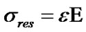 , where, E = 70 GPa [31]). On the other hand, the macrostrain (uniform strain) calculated from the shifts in peak positions, as
  , is 6 × 10⁻⁴ and the residual stress was calculated to be 42 MPa. The measured macrostrain and, hence, the associated residual stress are compressive as peak shifts are to the right (toward higher Bragg angle). As in the XRD diffraction method, only planes parallel to the surface contribute to the measured intensity, crystal planes parallel to the surface are under compression due to the water jet treatment. The measured compressive residual stress promotes the closing of surface and near surface pores, hence, raising the hardness in the “tribolayer” and retarding crack initiation and propagation during wear.
In order to investigate wear performance of the sintered
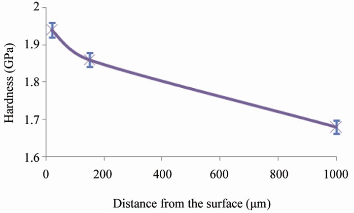
Figure 3. Variation of hardness at different depth below the surface.
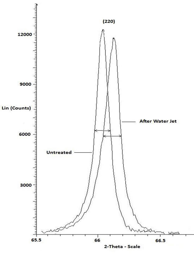
Figure 4. (220) X-ray diffraction peak of water jet treated and standard Al specimens.
Al-Si alloy after water jet treatment and compare to untreated and HIPed conditions, reciprocating wear tests were performed under 10 N normal load and 15 Hz frequency at three time intervals (10 min, 45 min and 90 min). For the water-jet treated specimens, the operating condition are as follows: 70 MPa from 64 mm standoff distance and 25 mm/s translation speed. Figure 5 depicts the data collected during wear tests. The figure shows a somewhat linear increase (with no transition) in weight loss with sliding distance. The fact that there are no wear transitions may indicate that the same wear mechanism(s) is operative throughout the duration of the tests. As we observed from the figure, 100 MPa specimens (under all conditions) exhibit higher weight loss compared to 600 MPa specimens (under corresponding conditions) due to lower porosity content in the specimens. On the other hand, for any given compaction pressure (i.e., percent porosity), water jet treated specimens exhibit lower weight loss compared to HIPed and untreated specimens.
Wear rates (i.e., slope of best fit weight loss versus sliding distance lines) are calculated from Figure 5 and their variation under various compaction pressures are plotted in Figure 6. It is clear that the specimens subjected to water jet treatment exhibit superior wear resistance compared to both untreated and HIPed specimens. For the specimens compacted at 100, 200 and 600 MPa, wear resistance increases by 4.3, 3.8 and 14.7% respectively after HIP, while after water jet treatment, there is 34.7, 36.4 and 57.3% increase in wear resistance, respectively.
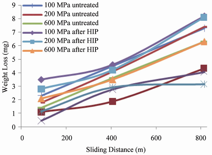
Figure 5. Weight loss vs sliding distance.
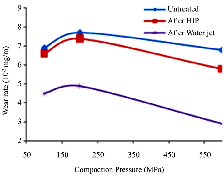
Figure 6. Wear rate at different operating condition.
The improvement in wear resistance of water jet treated specimens as opposed to hipped and untreated specimen can be explained in terms of variation in porosity and hardness levels post treatments. In the HIPed specimens, simultaneous application of heat and pressure reduces near surface internal voids and micro-porosity through a combination of plastic deformation, creep, and diffusion bonding. However, it has been found that, the final structure exhibit lower hardness due to softening at higher temperature due to HIP [34]. Water jet treatment was found to produce a compress layer and simultaneously increases hardness of the material.
To explain the initial increase and subsequent drop in wear rate with compaction pressure, detailed examination of the effect of porosity on wear mechanism is necessary. Scanning electron microscopy examinations of wear tracks reveal that delamination, plastic deformation and surface fracture are the dominant mechanisms during the wear process. Based on experimental observations in this study, several factors can be identified that affect the wear resistance of the water jet treated Al-Si alloys, namely, amount of porosity, pore size and shape and hardness of the subsurface region. The wear tracks of the samples were characterized by plastic deformation and damage in the form of plastic flow extending parallel to the sliding direction as shown in Figure 7(a). Surface pores act as stress concentration sites, the area around pores tend to fracture as a result of the stress exerted by the slider. This is evident from the cracks initiating from pore edge shown in Figure 7(b). Furthermore, Hertzian type cracks develop as a result of surface tensile stresses that evolve during Hertzian contact. These types of cracks normally extend perpendicular to the sliding direction. Figure 7(c) shows cracks perpendicular to the sliding direction which represents a clear evidence of Hertzian cracks developing during the wear process.
The other mechanism contributing to the observed wear is delamination. Initially, plastic deformation of surface layers due to cyclic normal and tangential loads take place, followed by crack or void nucleation in the deformed layers at pore sites (as pores act as stress concentration zones). Cracks nucleate at depth where shear stress is maximum as predicted by the Hertzian theory [35]. Then cracks grow nearly parallel to the surface and eventually become unstable and extend to the surface leading to the formation of thin, plate-like wear debris. Furthermore, the cracks extend and create a network of cracks by connecting different subsurface pores (Figure 7(d)). Pores serve as the origin and end of crack propagation, hence reducing the required length of crack propagation. This represents clear evidence that porosity in the subsurface layer accelerates delamination wear.
Based on SEM examination and Hertzian analysis (discussed in details in a previous work [13]), as expected, wear increase as porosity increases. However, at a critical pore size, where the contact area between the slider and sample surface is in the same order of magnitude as pore size, wear drops as the counterface slides into the pore, hence, not contributing to wear loss.
4. Conclusions
In the present work, the potential of using high pressure water-jet as a surface treatment for Al-Si alloys to mitigate the effect of surface porosity was assessed and the following main conclusions have emerged.
1) The amount of subsurface porosity and average pore size drops after water jet treatment.
2) Subsurface work hardening and compressive residual microstrain develop as a result of water jet pressure.
3) Ploughing of grains, transgranular and intergranular propagation of cracks are the mechanisms for material removal during water jet treatment.
4) High pressure water-jet treatment is more effective than HIP in promoting superior wear resistance. Prolonged heating at high temperature during HIP decreases the total amount of porosity at the expanse of decreased hardness. While water jet produces hard compressed subsurface “tribolayer” leading to increased wear resistance of the Al-Si alloy.
5. Acknowledgements
The author would like to thank Auto-21 for financial support, Bodycote International for performing HIP experiments and Vector Aerospace for performing water jet treatment.