1. Introduction
Recent technological advances in energy storage devices, sensors, actuators and information processing have boosted the development of Unmanned Aerial Vehicle (UAV) platforms with significant mission capabilities [1,2]. Unmanned aerial vehicles are important when it comes to perform a desired task in a dangerous and/or inaccessible environment. More recently, a growing interest in unmanned aerial vehicles (UAVs) has been shown among the research community [3]. The rotorcraft UAVs pose a set of advantages compared to the fixed wing UAVs, such as hovering, vertical takeoff and landing and aggressive maneuvering. Within the family of the rotorcrafts, Unmanned Quadrotor Helicopters (UQHs) have gained increasing attention among scientists and engineers [4]. A quadrotor is a 4-rotor vertical takeoff and landing vehicle that has the maneuvering abilities of traditional helicopters with significantly lower mechanical complexity. This low complexity increases dependability while reducing the cost of manufacturing, operation, and maintenance [5]. Quadrotor is usually used to develop control laws. This kind of helicopter tries to reach a stable hovering and flight, using the equilibrium forces produced by four rotors [6]. Quad rotors are therefore becoming a promising option for various unmanned military and civilian applications [5]. One of the advantages of the quadrotor configuration is its payload capacity. As a drawback, this type of UAV presents a weight and energy consumption augmentation due to the extra motors [7].
A Quadrotor Configuration
One can describe the vehicle as having four propellers in cross configuration. The two pairs of propellers (1, 3) and (2, 4) turn in opposite directions by varying the rotor speed; one can change the lift force and create motion. Thus, increasing or decreasing the four propeller’s speeds together generates vertical motion. Changing the 2 and 4 propeller’s speed conversely produces roll rotation coupled with lateral motion. Pitch rotation and the corresponding lateral motion are resulted from changing 1 and 3 propeller’s speed conversely. Yaw rotation is more subtle, as it results from the difference in the countertorque between each pair of propellers [2]. Figure 1 describes concept motions of quadrotor.
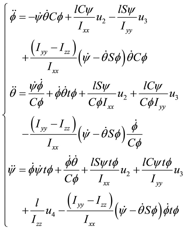
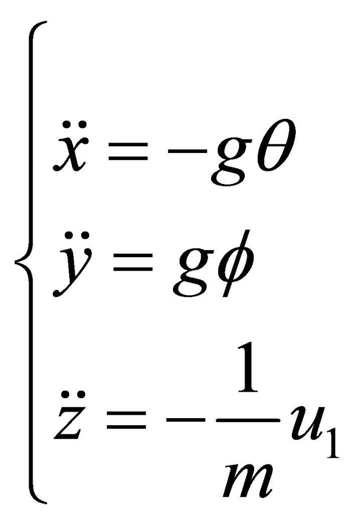
The six-degree-of-freedom airframe dynamics of a typical quadrotor involve the typical translational and rotational dynamical equations as in [8]. The dynamic model of a quadrotor is essentially a simplified form of helicopter dynamic that exhibits the basic problems in-

Figure 1. Quadrotor concept motions description.
cluding under-actuation, strong coupling, multi input/ multi output and unknown nonlinearities [9]. The automatic control of a quadrotor UAV is not a straight on mainly due to its under-actuated properties [10] and it is difficult to control all these six outputs with only four control inputs. Moreover, uncertainties associate with dynamic model also bring more challenge for control design [11].
In some papers the quadrotor helicopter has also been controlled using a linear controllers based on linearization models. In [12] two control techniques were compared, a PID and a Linear Quadratic Regulator (LQR), where a linearization model was considered to design the PID controller. The development of the LQR was based on a time variant model. The time-optimal control problem of a hovering quadrotor helicopter is addressed in [13]. Instead of utilizing the Pontryagin’s Minimum Principle (PMP), in which one needs to solve a set of highly nonlinear differential equations, a nonlinear programming (NLP) method is proposed. In this novel method, the count of control steps is fixed initially and the sampling period is treated as a variable in the optimization process. Nonlinear control problems for hovering quadrotor helicopters such as feedback linearization control and back-stepping control laws were studied in [14]. Back-stepping based techniques are utilized to design a nonlinear adaptive controller which can compensate for the mass uncertainty of the vehicle. Lyaponve based stability analysis shows that the proposed control design yields asymptotic tracking for the UAV’s motion in x, y, z direction and the yaw rotation, while keep the stability of the closed loop dynamics of the quadrotor UAV [11]. In [15] the rotor dynamics were considered in the model. The model was split up into two subsystems: the angular rotations and the linear translations and then back-stepping and sliding mode techniques were used to control the helicopter. In [7] a control law based on a standard back-stepping approach for translational movements and a nonlinear  controller to stabilize the helicopter are combined to perform path following in the presence of external disturbances and parametric uncertainties. However, this strategy is only able to reject sustained disturbances applied to the rotational motion both path following and stabilization problems. Time-optimal problems of control systems have attracted the attention of many researchers, especially in aerospace [16] and robotics [17] in the past few years. In this paper, we apply SISO control structure to achieve desired objectives such as: stability, control, robustness and disturbance rejection for attitude subsystem of quadrotor which is in fact an unstable plant. To achieve best time domain performance, SISO approach is used, the advantage of this strategy is that in every loop, the desired performance of loop is evaluated and if it is necessary, just the parameters of one controller would be manipulated. This paper is organized as follows. The dynamic model of quadrotor is given in Section 2. In Section 3, the control strategy is exposed. Simulation results are presented in Section 4. Finally, the major conclusion of the paper is drawn in Section 5.
2. Quadrotor Modeling
2.1. Description
The quadrotor has four rotors that are controlled independently. The movement of the quadrotor results from changes in the speed of the rotors. The structure of quadrotor in this paper is assumed to be rigid and symmetrical, the center of gravity and the body fixed frame origin are coincided, the propellers are rigid and the thrust and drag forces are proportional to the square of propeller’s speed. Figure 2 presents the structure of quadrotor and relative coordinate systems.
2.2. Kinematics of Quadrotor
The earth-fixed inertial reference frame is
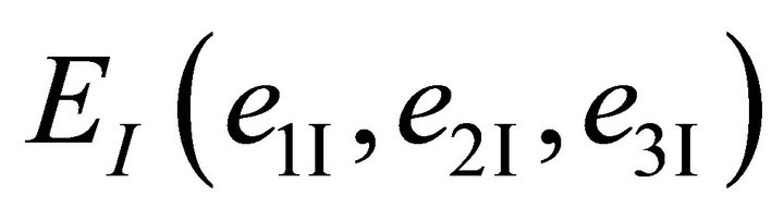 and the body-fixed reference frame is
 . The absolute position of the quadrotor is described by
  and its attitude by the Euler angles
 , used corresponding to aeronautical convention. The attitude angles are respectively called Yaw angle (
 rotation around z-axis), Pitch angle (
 rotation around y-axis) and Roll angle (
 rotation around x-axis). Let
 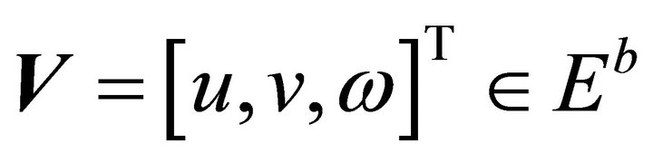 denote the linear velocity vector and
  denote the angular velocity vector of the airframe expressed in the body-fixed-frame. The relation between the velocities vectors
  and
and  is given by
 (1)
(1)
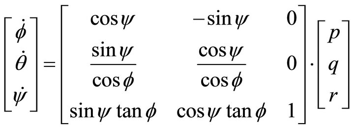
where  and
and  are respectively the trans-

Figure 2. The structure of quadrotor and relative coordinate systems.
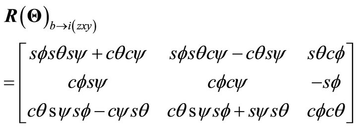
formation rotation and the rotation velocity matrices between  and
and :
:
 (2)
(2)
 (3)
(3)
where C·= cos(·) and S·= sin(·).
2.3. Dynamics of Quadrotor
Two different methods have been investigated to achieve dynamics of quadrotor. One can either use the Lagrangian equation or the Newton’s law. Let’s explain the second method which is more comprehensible.
The quadrotor is controlled by independently varying the speed of the four rotors. Hence four inputs are defined as follow:
 (4)
(4)
The quadrotor motion equations can be expressed with Newton’s law:
 (5)
(5)
 (6)
(6)
Also, to relate Euler angular rates to body angular rates, we have to use the same order of rotation. This gives rise to:
 (7)
(7)
By differentiating,
 (8)
(8)
I is the inertia matrix of the vehicle and 
 (9)
(9)
 . (10)
Assuming that the structure is symmetrical:
 . (11)
In some papers, the second term of the right side of the Equation (10),  is neglected [18]. This approximation can be made by assuming that:
• the angular rate about the z axis, r, is small enough to be neglected
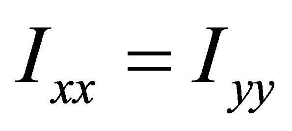
Let’s just assume, for the moment, that the moments of inertia along the x axis and y axis are equaled [19].
Hence,
 (12)
(12)
3. Control Strategy
The dynamic model of quadrotor developed in Section 2 will be linear around hovering situation. Hence the gyroscopic effects won’t be taken into consideration in the control design. In this paper, Taylor method is used to linear the model of quadrotor, the operation values of states and inputs around hovering mode are:
 (13)
(13)
The linear model of quadrotor is given as:
 (14)
(14)
 (15)
(15)
As the dynamic model shows, attitude subsystem of quadrotor, Equation (15),  are forced directly by input signals. The transfer function of
  is a second order with two poles on the origin, so the system is inherently unstable. PID controllers will be designed to stabilize and control the attitude subsystem of quadrotor.
3.1. PID Control
Proportional-plus-integral-plus-derivative (PID) controllers are widely used in the industry [20,21]. The main reason is its relatively simple structure, which can be easily understood and implemented in practice [22]. The widespread use of PID-type controllers in industries has affected efforts in the design and tuning of conventional PID controllers so as to achieve an optimal performance for the control system [23].
3.2. SISO Approach
As the Linear model of quadrotor shows, it is possible to use SISO approach for controlling attitude components. The transfer function of  is a second order with two poles on the origin. These components are directly affected by three inputs. One can consider block diagram for
  components. Figure 3 shows control block diagram that can be used for each one of
  components. As shown in Figure 3, one controller should be designed for each one of
  to achieve desired
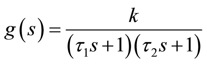
  directly. The g(s) model is assumed a second-order:
 (16)
(16)
And the desired PID structure is considered:
 (17)
(17)
3.3. PID Tuning
Tuning of PID controllers has been attracting interest for six decades. Numerous methods suggested so far try to accomplish the task by making use of different representations of the essential aspects of the process behavior [24]. Among the well-known formulas are the ZieglerNichols rule, the Cohen-Coon method, IAE, ITAE, and internal model control. These formulas are surveyed in [25]. Controller parameters are usually tuned so that the closed-loop system meets the following three objectives:
1) Stability and stability robustness, usually measured in the frequency domain;
2) Transient response, including rise time, overshoot, and settling time;
3) steady-state accuracy [26].
In this paper direct synthesis method [27] is used to drive PI-settings or PID-settings for set points. Optimization-based method can be regarded as a special type of optimal control.
For the system in Figure 3, the close loop set point response is:
 (18)
(18)
The idea of direct synthesis is to specify the desired close loop response and solve for corresponding controller.
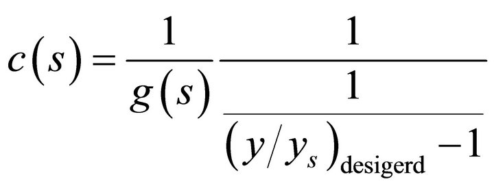 (19)
(19)
The g(s) model is assumed a second-order in Equation (16) and the desired close loop transfer function is a first order whit time constant: 
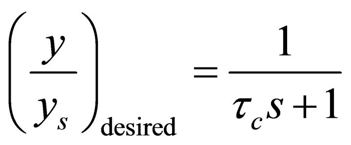 (20)
(20)
Substituting Equations (20) and (16) into (19) gives a “smith predictor” controller [28]:
 (21)
(21)
 is the desired close-loop time constant and is the sole tuning parameter for controller. Equation (21) is a series form PID-controller [27-29].
 (22)
(22)
3.4. Modifying the Integral Time for Improved Disturbance Rejection
The PID-setting in Equation (21) is desired by considering the set point response and the result must cancel the first order dynamics of the process by selecting the integral time . This is a robust setting witch result in very good response to set points and to disturbance entering at process out-put. However, it is well known that for integrating processes, the choice
 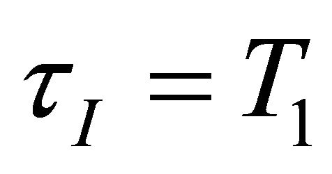 result in a long settling time for input load disturbances [30]. To improve the load disturbance response, the integral time should be reduced, but not too much because otherwise we get slow oscillations caused by having almost two integrators in series. A good tradeoff between disturbance response and robustness is obtained by selecting the integral time such that the slow oscillations are avoided. So the best choice for integral time is proposed in [31]:
 (23)
(23)
To summarize, the recommended SIMC PID-setting for the double integral process,  the parameters of PID are:
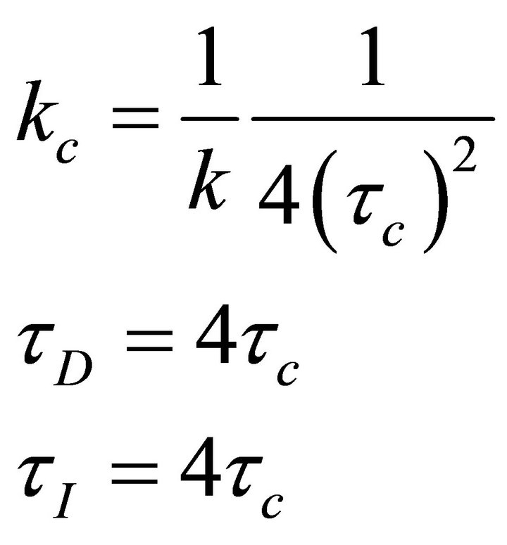 (24)
(24)
3.5. Recommended Choice for Tuning Parameter 
The value of the desired close loop time constant  can be chosen freely, the optimal value of
  is determined by a trade of between:
1) Fast speed response and good disturbance rejection by a small value of .
.
2) Stability, robustness and small variation by a large value of .
.
An alternative is to use the integral error as a performance index. The followings are some commonly used criteria based on the integral error for a step set-point response:
 (25)
(25)
In this paper IAE criterion is used as an objective function to chose . Alternatively, a self-learning evolutionary algorithm (EA) can be used to choose
  to meet multiple design objectives in time domain. In this paper the Genetic Algorithm is used for this work.
The best choice for  is obtained from Genetic Algorithm that satisfies minimum value for IAE is:

3.6. Simulation Results
The proposed control strategy has been tested by simulation in order to check the performance attained for the stabilization, disturbance rejection and tracking problems with real model of attitude subsystem of quadrotor.
The values of the model parameters used for simulations are:

Figure 4 shows the result of regulation attitude component with desired controller vs. the back-step controller. As the Figure 4 shows the response of desired controller is faster than back-step controller and this matter is so important because attitude subsystem is inner loop in quadrotor plant and when the transitional components are controlled, the speed of inner loop response plays very important role.
Other objective that is considered in this paper is load disturbance rejection. Figure 5 shows the manner of two controllers to rejection the step disturbance that adds to output.

Figure 4. Attitude regulation signals of quadrotor.


Figure 5. Disturbance rejection of quadrotor attitude components.

Figure 6. Tracking of the predefined trajectory attitude components of quadrotor.
The results show that desired controller rejects disturbance in minimum time. There is an overshoot in responses that is usual because of the fast response. Finally we need a fast response because of the reason that previously mentioned.
In Figure 6 tracking of the predefined trajectory for attitude components with two controllers are surveyed.
As shown in Figure 6, the tracking of the predefined trajectory is done with two controllers so good. In first seconds the desired controller has better response than back-step controller.
4. Conclusions
In this paper a SISO control structure of quadrotor is presented. Analytical optimization method is used to tune a conventional PID controller for stabilization and disturbance rejection of quadrotor. The time domain performance of designed control structure is evaluated with IAE objective function. The results of simulation in Simulink/Matlab software, illustrate the efficient of applied control strategy.
Future works will focus on model predictive control design for quadrotor UAV to has ideal tracking and stabilization.