1. Introduction
Many modern broadcasting wireless systems (such as wireless local area networks, digital audio and digital video broadcasting, WiFi, WiMAX, LTE) use multicarrier modulations like OFDM [1].
One of the advantages of OFDM modulations is its resistance against multipath. Its drawback is the large PAPR value which is a measure of the modulated signal envelope dynamics. This makes the modulated signal very sensitive to the distortions introduced by the non linearity of power amplifiers. Hence, this increases the cost of the RF power amplifier which is one of the most expensive components in the radio hardware. Many strategies are introduced by the researchers to reduce the PAPR value of the OFDM signal [2-5].
In this paper, a proposed scheme is suggested to achieve 0 dB PAPR value. Therefore, it outperforms the previous techniques in terms of PAPR reduction value. It depends on a proposed block, named CA modulation, which is inserted in the conventional system to fix the OFDM signal amplitude. The mathematical model of the proposed scheme is presented. Furthermore, the complexity modification is studied. Additionally, many MATLAB simulation programs are executed to compare the performance of the proposed and the conventional OFDM systems in terms of time and frequency domains, in-band distortion, PAPR, BER for multipath fading channels, and equalization. Moreover, the impact of the proposed scheme design parameter is explained. The simulation showed that the proposed system behaved better performance than the conventional one in all measurement terms.
The paper is organized as follows; Section 2, introduces the mathematical model for the conventional OFDM system. The PAPR definition and some of the major existing methods for reducing it are defined in Sections 3 and 4, respectively. Section 5, gives a comprehensive mathematical analysis for the proposed system. Section 6, evaluates the complexity proposed by the proposed scheme. Extensive simulation results are discussed in Section 7. Finally, conclusions are extracted in section 8 followed by the relevant references.
2. Conventional OFDM System Model
2.1. The Transmitter
The schematic diagram of the OFDM system is shown in Figure 1. At the transmitter, the encoded data are
transformed to  parallel sequence of complex numbers in one of several possible mapping formats (QPSK, 16-QAM, 64-QAM, etc.). Then, the N-points Inverse Fast Fourier transform (IFFT) is applied to the resulting modulated symbols. After that, a cyclic prefix (CP) is added to the resulting signal and it is converted to a serial sequence. Afterwards, the resulting signal is analogy modulated after the conversion to analog signal. Finally, the resulting signal is transmitted through the wireless channel [2].
One  sampled baseband OFDM symbol after the IFFT can be expressed as:
 (1)
(1)
where  and
and  represents the
  complex modulated data symbol of duration
 . This OFDM symbol can be written in a
  column vector as [1]:
 (2)
(2)
where  denotes the transpose of
  and
and  is the OFDM symbol number.
  and
and  are the complex
  points IFFT
  matrix and the
  complex OFDM modulated data symbol (column)
  vector, respectively.
  and
and  can be expressed as follows:
 (3)
(3)
 (4)
(4)
 (5)
(5)
 (6)
(6)
where the  samples and the
  subcarriers are represented by the rows and the columns of the
  matrix, respectively. They can be separated as shown by (5), (6) into the two vectors;
  (the
(the  complex samples vector which varies for each subcarrier) and
  (the
(the  complex subcarriers vector). In order to achieve unitary,
  should be scaled by
  [6].
[6].
After CP insertion, the samples variation is modified to  where
where  is the number of CP samples which should be
 . Therefore,
  vector should be regulated as (7). Consequently,
  and
and  dimensions are expanded to
 ,
,  , respectively as implied in (8).
 (7)
(7)
 (8)
(8)
2.2. The Energy Loss
The use of a CP in the transmitted signal has the disadvantage of requiring more transmit energy. The loss of transmit energy (or loss of signal-to-noise ratio (SNR)) due to the CP is [7]:
 (9)
(9)
It is worth mentioned that  should be divided by
  to compensate the wasted energy due to the CP insertion.
2.3. The Wireless Communication Channel
The transmitted waveform gets corrupted by noise. The multipath fading channel having impulse response  of length
  can be expressed as follows:
 (10)
(10)
where  and
and  represent the complex fading and the propagation delay of the
  path, and
  is the number of multipaths, respectively.
2.4. The Receiver
At the receiver as shown in Figure 1, the received signal is analogy demodulated and then it is converted into a digital format. Afterwards, the CP is removed from the resulting signal and it is transformed into  parallel samples. Then, the signal is transformed into the frequency domain via the
  points FFT. Thereafter, frequency domain equalization (FDE) is performed. Finally, the demapping and parallel to serial processes are performed. After removing the CP, the received symbol can be written as:
 (11)
(11)
where  is the
  complex noise vector contributed by AWGN which is Gaussian distributed with zero mean.
  is the
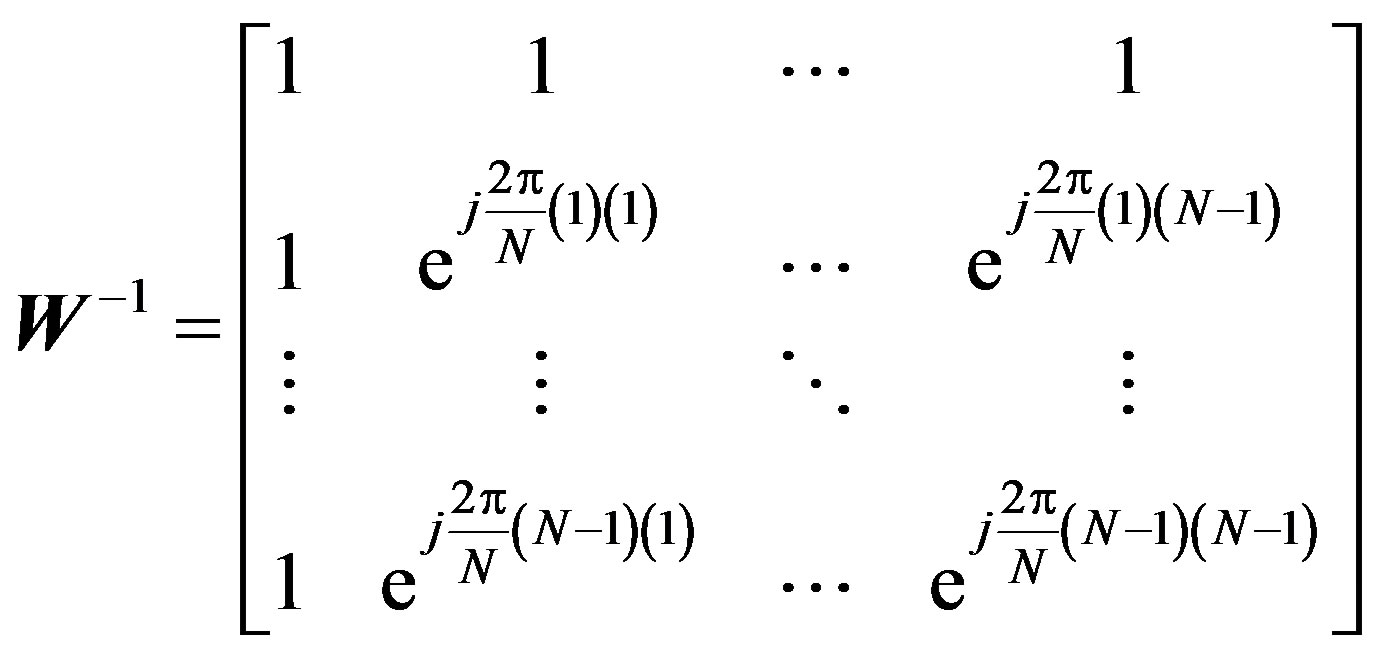
  circulant channel matrix describing the multipath fading channel. It can be diagonalized by the FFT and IFFT as follows [8]:
 (12)
(12)
 (13)
(13)
where  is
is  diagonal matrix containing the FFT of the circulant sequence of
 .
.  is the complex
  points FFT
  matrix.
After the  points FFT, the resulting symbol is:
 (14)
(14)
The FDE complex coefficients  can be derived according to the minimum mean square (MMSE) criterion as follows [9]:
 (15)
(15)
where  designates the complex conjugate transposetion of
 . A major advantage of the equalization in frequency domain is the low computational complexity. The price to be paid is a reduction in the data rate caused by the insertion of the CP [10]. The symbol after FDE can be expressed as:
 (16)
(16)
After demapping, these noise can be greatly minimized and the original symbol  can be recovered.
3. Peak-to-Average Power Ratio
Since OFDM signals are modulated independently in each subcarrier, the combined OFDM signals are likely to have large peak powers at certain instances. The peak power is generally evaluated in terms of PAPR.
Accordingly, the PAPR of the OFDM signal which is defined as the ratio of the maximum power divided by the average power of the signal is expressed as:
 (17)
(17)
where  returns the magnitude of
  and
and
 denotes the expectation operation [2,11].
The Cumulative Distribution Function (CDF) of the amplitude z of an OFDM signal sample [11] is given by:
 (18)
(18)
The CDF of the PAPR for an OFDM data block can be found in [11] as:
 (19)
(19)
where  is the number of subcarriers. For an oversampled OFDM, this last formula should be modified to:
 (20)
(20)
where the PAPR of an oversampled signal for  subcarriers is approximated by the distribution for
  subcarriers without oversampling. For four times oversampled OFDM signals,
  is a good approximation [12].
Therefore, CCDF of the PAPR for an oversampled OFDM data block is:
 (21)
(21)
4. PAPR Reduction Methods
Many strategies for reducing the PAPR have been accomplished such as clipping [13], coding [14], peak windowing [15] and tone reservation [16]. Unfortunately, most of these schemes are unable to achieve a large reduction in the PAPR with a low complexity, low coding overhead and without performance degradation.
Partial Transmit Sequence (PTS) method is a well known method which can reduce the OFDM PAPR value. A major drawback of PTS method is its high computational complexity due to the necessity of large number of Inverse Fast Fourier Transforms (IFFT) [17].
The selective mapping (SLM) scheme is one of the most effective PAPR reduction schemes in OFDM systems. SLM scheme can achieve several decibels of PAPR reduction and hence significantly improves the transmission power efficiency [18]. One of its major disadvantages is the transmission of side information bits in order to enable the receiver to recover the transmitted data blocks. The reduction of PAPR value in SLM scheme is better than obtained in PTS method but a large number of Inverse Discrete Fourier Transform (IDFT) blocks are required. This results in increased computational and hardware complexity [18].
Dummy Sequence Insertion (DSI) scheme is another method for PAPR reduction. The drawbacks of the DSI method is that the length of data is increased which affects the bandwidth. This degrades the transmission efficiency [19].
Additionally, in [5], an efficient technique for the OFDM system using wavelet transform is proposed. It reduces the PAPR value from 8.8 dB for conventional OFDM system to 1.5 dB. While in [20], a novel multicarrier spread spectrum watermarking scheme for the application of image error concealment using multicarrier-code division multiple access with binary phase shift keying transmission in Rayleigh fading channel is proposed. This scheme can be used for PAPR reduction. Furthermore, in [21], The reduction of dynamic range or PAPR is made by using a compander in the Space Division Multiplexing/Companded Orthogonal Frequency Division Multiplexing (SDM/COFDM) system.
In [22-24], A constant envelope paired burst OFDM was proposed to achieve 0 dB PAPR. Its main idea has been just adding two constant envelope OFDM signals which have been amplified using a single grossly nonlinear amplifier. The constant envelope OFDM signal can also be thought of as a phase transformation of the OFDM signal [25]. In this paper, our proposed technique uses a different method to achieve the 0 dB PAPR.
5. The Proposed Scheme
5.1. The Transmitter
In this section, we describe the structure of a proposed efficient OFDM scheme to avoid the OFDM PAPR problem. It is shown in Figure 2. At the transmitter, a new block named by “Constant Amplitude (CA) Modulator” is inserted after the IFFT process. It consists of three sub-blocks as shown in Figure 3. Firstly, a leading zero sample is inserted prior to each OFDM symbol via “Inserting Zero Sub-block”. Secondly, extra samples are inserted between each two adjacent samples of the resulting OFDM symbol via “Inserting Samples Subblock”. These extra samples are gradually increased or decreased according to the primitive samples. Finally, each sample value of the resulting signal is converted into 0 or  value via “Comparing Samples Subblock”. This is based on the comparison between it and a reference generated signal.
Therefore, 0 dB PAPR value is expected to be achieved via our proposed CA modulator. That is because the output of the CA modulator has a constant amplitude and the randomly amplitude peaks of the OFDM phenomenon is eliminated.
The mathematical analysis of the proposed scheme can be summarized as follows:
1) After IFFT block, the complex OFDM symbol , expressed by (2), is separated into its real and imaginary parts as follows:
 (22)
(22)
where  and
and  donate the real and the imaginary part of
 . Subsequently, our proposed block (CA modulator) is inserted for each part.
2) At the real branch, after “Inserting Zero Sub-block”,
the resulting real OFDM symbol  has
has  samples. It can be written as:
 (23)
(23)
3) After “Inserting Samples Sub-block”, the resulting real OFDM symbol  length is increased to
 . It can be written as:
 (24)
(24)
 (25)
(25)
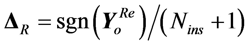
where  is the extra inserted samples between each two adjacent samples in
  symbol.
  is the difference between these two adjacent samples.
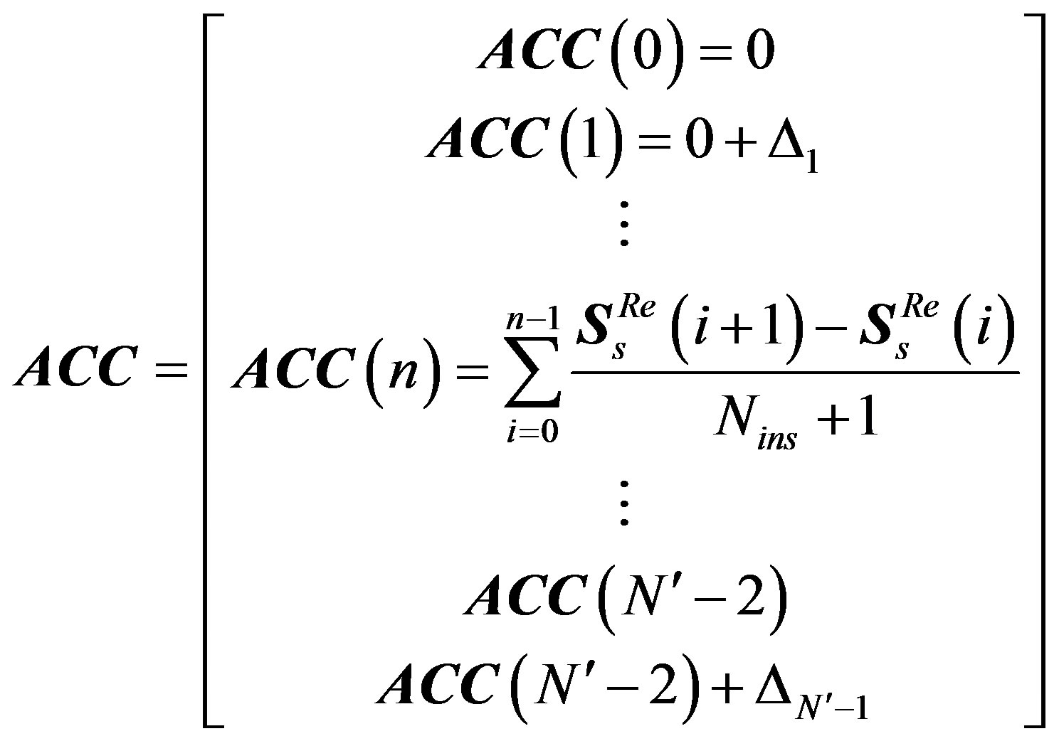
4) After “Comparing Samples Sub-block”, each sample value in the  symbol is converted into 0 or
  value. This is executed by the following steps:
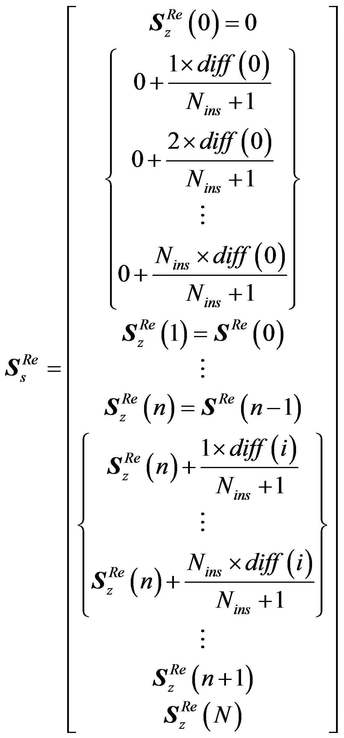
a) Generate a reference symbol called accumulated stepped samples .
.
b) Compare each sample value in  with
with , where
  is the sample number.
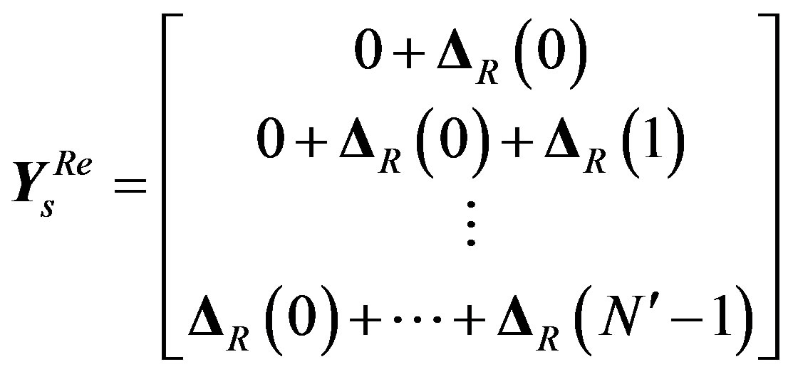
c) Produce the resulting OFDM symbol  and update
  symbol as follows:
I) If , the output
  and
and .
.
II) If , the output
  and
and .
.
III) If , the output
  and
and .
.
The output  symbol size is not changed from
 .
.  and
and  can be represented as follows:
 (26)
(26)
 (27)
(27)
 (28)
(28)
 (29)
(29)
5) At the imaginary branch, the same analysis can be developed to derive . Therefore, the final modified transmitted OFDM symbol
  can be expressed as:
 (30)
(30)
6) Finally, the CP is inserted. The resulting symbol can be expressed as:
 (31)
(31)
where  is the modified CP length due to the extended resulting symbol.
5.2. The Energy Loss
The use of a CA modulator in the transmitted signal has the disadvantage of requiring more transmit energy. The loss of transmit energy due to the CA modulator followed by the CP insertion is:
 (32)
(32)
 (33)
(33)
It is worth mentioned that  should be divided by
  to compensate the wasted energy.
5.3. The Receiver
At the receiver as shown in Figure 2, the received signal is analogy demodulated and then it is converted into a digital format. Afterwards, CP is removed and our proposed “Constant Amplitude (CA) De-modulator” is inserted to reverse the impact of the CA modulator. It consists of three sub-blocks as shown in Figure 3. Firstly, the OFDM symbol is regenerated via “Samples Generation Sub-block”. Secondly, the extra inserted samples are removed from the resulting OFDM symbol via “Removing Residual Samples Sub-block”. Finally, the leading zero sample is removed from the forefront of each OFDM symbol via “Removing Leading Zero Subblock”.
Then, the signal is transformed into the frequency domain via the  points FFT. Finally, the demapping and parallel to serial processes are performed without any equalization as in the conventional system.
The mathematical analysis can be summarized as follows:
1) After CP removal, the resulting symbol is:
 (34)
(34)
2) The noisy demodulated received symbol  is separated into its real
  and imaginary
  parts. Subsequently, our proposed block (CA de-modulator) is inserted for each part.
3) At the real branch, after “Samples Generation Sub-block”, the OFDM symbol is regenerated. This is executed by the following steps:
a) Generate a reference symbol with a leading zero sample .
.
b) Update  symbol as follows:
I) If , then
 .
.
II) If , then
 .
.
III) If , then
 .
.
c) Produce the resulting OFDM symbol 
 . It can be written as follows:
 (35)
(35)
 (36)
(36)
4) After “Removing Residual Samples Sub-block”, the resulting real OFDM symbol  size is
 . it can be exposed as:
 (37)
(37)
5) After “Removing Leading Zero Sub-block”, the resulting real OFDM symbol  size is
 . It can be exposed as:
 (38)
(38)
6) At the imaginary branch, the same analysis can be developed to derive . Therefore, the final modified recovered OFDM symbol
  can be expressed as:
 (39)
(39)
where  is the OFDM symbol after removing CP in the conventional system. It differs from
  by means of:
• Channel noise: Those are mainly produced due to the multipath fading channel. These noises are categorized into:
◦ In phase noise which does not change the signal polarity. This noise is eliminated via our proposed scheme. That is because only positive or negative levels are used in our proposed CA modulator, while the zero level is very rarely to be occurred due to the OFDM nature. On the contrary, the conventional system can't eliminate this noise in this stage.
◦ Out of phase noise which changes the signal polarity. Additionally, the noise which affects the zero samples values. These types of noise can’t be eliminated by both systems.
• System accuracy: This produces errors from the imperfections of the samples recovery at “samples generation sub-block”. These errors are greatly minimized by increasing  value but this degrades the system throughput.
7) After the  points FFT, the resulting
  symbol is
 .
.
8) After demapping, these errors can be greatly minimized and the original symbol  can be recovered.
6. Complexity Evaluation
6.1. Complexity Analysis for the Proposed CA Modulator
The complexity added to the conventional OFDM transmitter by the CA modulator can be illustrated as follows:
• In order to delay the input samples one clock to insert the zero sample prior to each OFDM symbol, only a simple register with the sample width is required for the “Inserting Zero Sub-block”.
• Only one simple subtractor used  times per OFDM symbol, one simple adder used
  times per OFDM symbol, and one divider by
  are demanded by the “Inserting Samples Sub-block”. The divider can be replaced by a simple shift registers, if
  is a power of 2.
• A simple comparator used  times per OFDM symbol and a simple adder used
  times per OFDM symbol, are the price to be paid for “Comparing Samples Sub-block”.
Therefore, the additional operational complexity is two simple adders, one simple subtractor, and one simple comparator per one CA modulator.
6.2. The Complexity Analysis for the Proposed CA De-Modulator
The excess in the conventional OFDM receiver complexity via the CA de-modulator can be summarized as follows:
• One simple adder used  times per OFDM symbol, and simple comparator used
  times per OFDM symbol are needed by “Samples Generation Sub-block”.
• Simple switches are used to eliminate the residual samples for both “Removing Residual Samples Subblock” and “Removing Leading Zero Sub-block”.
• Therefore, the additional operational complexity is one simple adder and one simple comparator per one CA modulator.
6.3. The Overall Additional Complexity Computation
The overall transmitter additional complexity is four simple adders, two simple subtractors, and two simple comparators. That is because each transmitter contains two CA modulators. Further, the overall receiver additional complexity is two simple adders and two simple comparators. Therefore, the proposed scheme requires additional six simple adders, two simple subtractors, and four simple comparators.
Noteworthy, the complexity of our proposed technique is very low compared to the previous constant envelope technique in [23-25] which requires oversampling, integrator, and grossly look up table “memory storage” at the transmitter. According to the receiver, a huge complexity is added. It requires a band-pass filter (which is area consuming), two complex multipliers, a grossly look up table, two low-pass filters, arc-tan function generator, phase unwrapper, matched filters, and hard decisions. Additionally, the frequency domain equalizer is needed contrary to our proposed scheme.
6.4. The Complexity Reduction Analysis for the Proposed Scheme
The equalization process is removed in the proposed scheme. That is because of the presence of the “Samples Generation Sub-block”. Therefore, the receiver complexity is extremely reduced.
Additionally, hermitian OFDM can be used. Hence, only real outputs are occurred. Therefore, only one CA modulator/ de-modulator is used instead of two. Then, the overall additional complexity is reduced by a factor of 2.
7. Simulation Results and Discussions
7.1. Simulation Setup
Monte Carlo MATLAB simulation experiments have been carried out to study the performance and the effectiveness of the proposed scheme. WiMAX system has been used as an example of the conventional OFDM system [26]. The WiMAX and the CA modulation block parameters used for these simulations are illustrated in Table 1. Both AWGN and multipath channels are considered. For the multipath channel, we consider ITU Pedestrian A and ITU Vehicular A channels [27] with AWGN. The delay profiles of the two channels are described in Table 2.
7.2. Time and Frequency Domains Behaviors
In this subsection, the characteristics of both conventional and proposed OFDM systems are studied. The upper part of Figure 4, compares 50 real part samples for both systems output. On the contrary to the conventional system, our proposed system produces a constant amplitude signal. Therefore, 0 dB PAPR value is expected to be achieved.
The lower part of Figure 4, compares the frequency domain for both systems output. It is clear that the frequency domain of the proposed system concentrates the power in the DC component and the side bands. Therefore, it suffers from the severe frequency selectivity channels.

Table 2. Channel delay profiles of ITU Pedestrian A and Vehicular A channels [27].

Figure 4. Time and frequency domains for both systems.
7.3. In-Band Distortion Calculation
Error vector magnitude (EVM) is a popular figure of merit adopted by various communication standards for evaluating in-band distortions introduced in a communication system.
Figure 5, illustrates the EVM concept. Denote by  the reference signal,
  its distorted version, and
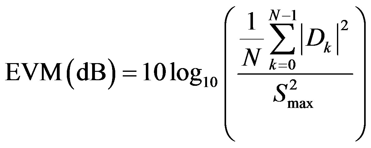
  the error signal (vector). The so-called EVM is defined as [26,28]:
 (40)
(40)
 (41)
(41)
where  is the maximum amplitude of the constellation points that define
 , and
, and  is the number of points in a measurement. For single carrier modulations,
  is, by convention, the highest power point in the reference signal constellation. More recently, for multicarrier modulations,
  is defined as the reference constellation average power [29].
The influence of the transmission channel is not considered and the signal distortion is caused only by CA modulation to focus only on its undesirable effects. 103 OFDM symbols are generated to calculate EVM value. In our calculations,  and
and . The simulated EVM value for the given simulation area is 14.85% or –16.64 dB.
7.4. PAPR Performance
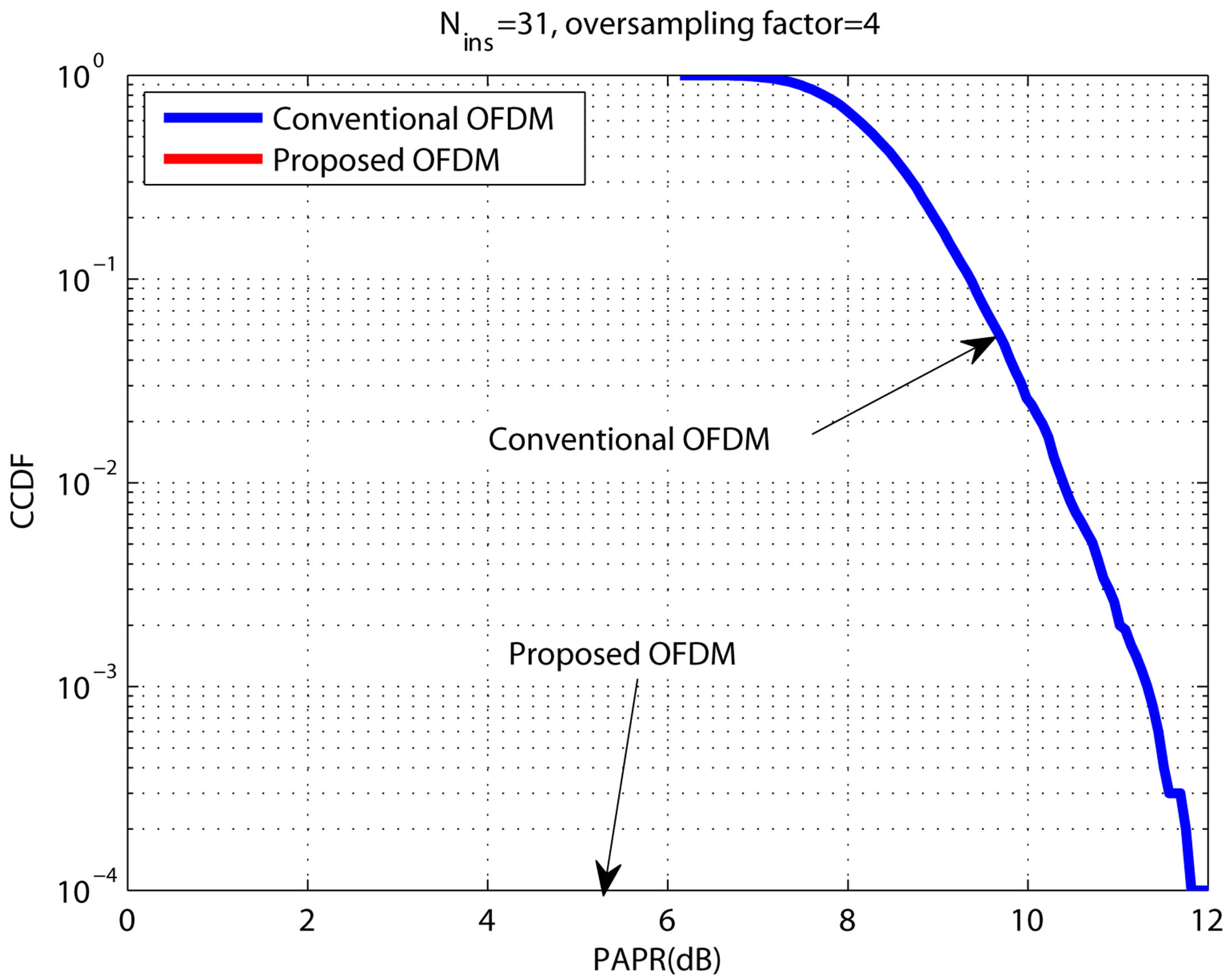
In this subsection, the CCDFs of the PAPR for the conventional and the proposed OFDM systems are evaluated

Figure 5. Illustration of the EVM definition.
and compared. 104 data blocks are generated to calculate the CCDFs of the PAPR. To have a precise PAPR value, the oversampling factor should take into account. It is chosen to be 4 [11].
In Figure 6, plots of the CCDFs of the PAPR for both systems are shown. It is clear that the conventional WiMAX system has PAPR values in the range ~6.5 - 11.5 dB, while the proposed system has 0 dB PAPR value. That is because of the constant amplitude achieved by the proposed block “CA modulator”. This means that there are no peaks in the transmitted signal.
7.5. BER Performance
Figure 7 illustrates the BER performance of the conventional and the proposed OFDM systems with different channel types. The Minimum Mean Square Error (MMSE) Equalizer is used for the conventional system, while the proposed system does not need any Equalization
 BER Vs Eb/No
Figure 6. The CCDFs of the PAPR for the conventional and the proposed OFDM systems.
 Eb/No(dB)
Figure 7. BER vs. Eb/No for the conventional and the proposed OFDM systems.
processes. It can be observed that the proposed system provides a significant BER performance improvement over the conventional system.
7.5.1. For AWGN Channel
The performance of the proposed system is better than that of the conventional system over all  (the energy per bit to noise power spectral density ratio) values. At BER = 10–2, the performance gain is about 6.6 dB for the proposed system when compared to that of the conventional system. This is attributed to the use of only positive or negative levels in our proposed CA demodulator, while the zero level is very rarely to be happened due to the OFDM nature. Therefore, the effect of the In-phase noise can be completely removed. However, the impact of Out-of-phase noise can’t be eliminated. That is because it changes the signal polarity.
It is worth mentioned that our proposed system performance is superior to the best case of the previous constant envelope OFDM system [25] by 2 dB gain.
7.5.2. For ITU Pedestrian-A Multipath Fading Channel
The performance of the proposed system is also better than that of the conventional system over all  values. At BER = 10–2, the performance gain is about 8.4 dB for the proposed system when compared to that of the conventional system.
The improvement in the performance gain is due to the multipath fading channel effect. Hence, our CA demodulator outperforms the equalization process in the conventional system for multipath noise impact removal. In addition, extra samples are inserted in the proposed system. Therefore, the length of the CP is increased. Consequently, BER performance enhancement can be achieved but, the price to be paid is a reduction in the system transmission throughput.
7.5.3. For ITU Vehicular-A Multipath Fading Channel
The performance of the proposed system outperforms the conventional system for . At BER = 10–2, the performance gain is about 19 dB for the proposed system when compared to that of the conventional system.
While the conventional system behaves better than the proposed system for . The performance significantly degradation in the high
  regime is due to the huge excess in the proposed system symbol length. Therefore, the proposed system is affected by the Doppler spreading in the multipath fading channel. This is more evident in the Vehicular-A channel simulation results where the frequency selectivity is severe. Under using a good channel coding or channel adaptive modulation scheme, this limitation can be overcome.
Due to the long proposed system symbol length, the performance is the best under Vehicular-A channel then under Pedestrian-A channel and finally under AWGN channel for low  regime
 . This order is reversed for high
  values.
7.6. Impact of Equalization
In this subsection, the effect of the equalization process for the conventional and the proposed OFDM systems are studied as shown in Figure 8. Both Zero Forcing (ZF) and MMSE equalization process are compared under Vehicular-A channel. It is clear that the equalization processes enhances the performance of the conventional system, while it degrades the proposed system performance. That is because besides, the original function of the CA de-modulator in the proposed system (which is to regenerate the OFDM samples), it behaves as an equalizer for the In-phase channel noise removal. Therefore, the proposed system does not need any equalization processes. In addition, due to the perfect channel estimation used, both ZF and MMSE equalization have the same performance.
7.7. Impact of 
The main parameter which affects the proposed scheme is  value. Its effect on the system accuracy, In-band distortion, output symbol length, complexity, and the transmission throughput are studied.
7.7.1. The System Accuracy
Under no channel conditions, Figure 9 compares the original real OFDM symbol  and the recovered one
 . It is clear that the error is reduced and hence, the system accuracy is increased for high
  values.
 Eb/No(dB)
Figure 8. The Equalization effect for both the conventional and the proposed OFDM systems.
That is because for higher  values, the less step size
  is reduced. Then, the CA de-modulator can more precisely follow the original symbol.
Figure 10 displays the BER performance of the proposed OFDM system under Vehicular-A multipath fading channel environment. It is clear that for higher  values, better performance is achieved. However, the price to be paid is the system throughput or the system speed degradation.
7.7.2. In-Band Distortion
Under no channel conditions, the EVM values are calculated for different  values as displayed in Table 3. It is clear that for higher
  values, lower EVM values are obtained. Hence, better performance is achieved.

Figure 9. Original vs. recovered OFDM symbols for different  values.
 Eb/No(dB)
Figure 10. BER for different  values under VehicularA multipath fading channel.

Table 3. EVM values vs. different  values.
7.7.3. The Symbol Length
For  are inserted, the OFDM symbol length is increased by
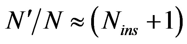 . Therefore, the processing time is increased which affects the system speed.
7.7.4. The System Complexity
Due to the serial manner used to perform the proposed CA modulation, the higher  value means more processing time to produce the output. Therefore,
  values do not affect the system complexity but it affects the system speed.
7.7.5. The Transmission Throughput
For  increment, the OFDM symbol length
  is increased. Consequently, there is no effect on the sampling rate, the required bandwidth, the IFFT length, and the subcarrier spacing. However, the transmission throughput is decreased to
 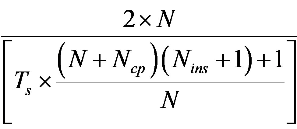 compared to
  in a first case using QPSK modulation.
However, if the OFDM symbol length  is kept fixed, the sampling rate is increased. Hence, the required bandwidth is enlarged. Moreover, the IFFT length is decreased. Consequently, the subcarrier spacing is increased. However, there is no degradation in the transmission throughput.
8. Conclusion
OFDM is a method of transmitting data simultaneously over multiple equally-spaced carrier frequencies, using Fourier transform processing for modulation and demodulation. High PAPR value is the most serious OFDM drawbacks. On the contrary to traditional techniques, the proposed scheme in this paper (which uses the suggested CA modulation block) has achieved 0 dB PAPR value. Consequently, the power amplifier of the transmitter can operate at the optimum (saturation) point. Hence, its efficiency and battery life are maximized. The mathematical model for the proposed system has been discussed. Furthermore, Extensive simulation programs have been executed to study the behavior of the proposed system compared with the traditional one. The proposed system has outperformed the traditional one in terms of BER under AWGN and multipath fading channels. At BER = 10–2, 6.6 dB, 8.4 dB, and 19 dB performance gains have been achieved for the proposed system over the conventional one under AWGN, ITU Pedestrian-A, and ITU Vehicular-A multipath fading channel, respectively. Additionally, the proposed system has outperformed the previous constant envelope system in terms of hardware complexity and BER performance. Moreover, CA modulation has introduced EVM = 14.85% for In-band distortion under the given simulation parameters. In addition, the equalization process has not required for the proposed scheme. Finally, the impact of  has been studied. For higher
  values, the system accuracy has been increased but with a cost of system throughput degradation.