Non-Axisymmetric Mass Transfer Phenomenon behind an Orifice in a Curved Swirling Flow ()
1. Introduction
The wall thinning is one of the important topics of interests for the safety management of the pipelines in nuclear/fossil power plants. Most of pipe-wall thinning is caused by the flow accelerated corrosion (FAC) of low carbon steel pipelines. The mechanism of FAC is mainly governed by the mass transfer phenomenon of the ferrous ions from the low carbon steel into the bulk flow and is highly accelerated by turbulent flow. Therefore, FAC is often observed in the flow behind an orifice and in an elbow with highly turbulent flows [1-5].
In 2004, a pipeline accident has occurred in the Mihama nuclear power plant in Japan, which resulted from pipe-wall thinning by FAC [6,7]. The geometry of pipeline in Mihama is illustrated in Figure 1. It is known that the non-axisymmetric pipe-wall thinning occurs behind the orifice in the A-line, while the wall thinning in the B-line behind the orifice keeps almost symmetric. The most interesting point of the pipe-wall thinning is the non-axisymmetric wall thinning in the cross-section of the A-line behind an orifice, which results in a higher thinning rate on one side of the pipe than on the other side. It was also found from the scaled model experiment that the swirling flow was observed in the pipeline [7]the magnitude of which was estimated by the swirl number defined by the ratio of the circumferential momentum to the axial one and equal to 0.26 in the upstream of the orifice. Since then, several studies have been carried out in literature [8-13] to elucidate the mechanism of wallthinning of the pipe.
One of the cause of the non-axisymmetric wall-thinning is the orifice bias error [8,11]. This bias error can occur in the pipeline, when a circular orifice plate is installed to the pipeline, while the pipeline has a minor diameter error smaller than 0.8% of the diameter by the
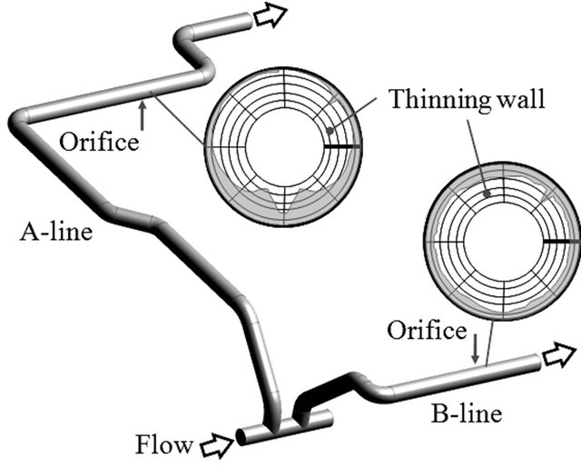
Figure 1. Prototype pipeline of Mihama power plant.
Japanese Industrial Standard (JIS G3456). Due to the unstable nature of the flow behind the orifice under the influence of swirling flow, the flow reattaches on one side of the pipe wall and results in the non-axisymmetric flow field behind the orifice [11]. The critical bias error is known to be 0.4% of the pipe diameter, which is combined with the swirl number 0.2 of the swirling flow, generates the non-axisymmetric flow behind the orifice [12]. This mechanism is supported by the measurement of mass transfer rate behind the orifice by naphthalene sublimation method [12]. On the other hand, the flow behind the orifice can be influenced by the pipeline elements, such as the elbow and the some other complex pipeline shape in the upstream. This is the case of A-line in the Mihama. However, the influence of the pipeline elements in the upstream has not been fully understood yet due to the complex nature of the flow field related to the FAC case.
The purpose of this paper is to provide a key to understand the complex mechanism of non-axisymmetric wallthinning of a pipeline by the mass transfer rate measurements using a benzoic-acid dissolution technique.
2. Experimental Apparatus and Procedures
The measurement of mass transfer rate was carried out using a closed-circuit water tunnel, which was described in Ref. [11]. A schematic layout of the experimental apparatus is shown in Figure 2. A honeycomb is located in the upstream of a swirler to remove the influence of the secondary flow in the upstream. The swirl flow was generated by the swirler, which is made of 6 plate vanes of inclined angle of 45 degrees. In the downstream, the long elbow, the straight pipe section of length 10d, the circular orifice having a diameter ratio of 0.6 are placed before entering into the test section for the measurement of mass transfer rate behind the orifice. The long elbow has an inner diameter 52.7 mm and the radius of centerline curvature 76.2 mm (JIS B2313-1991). The inner diameter of the test pipe is d = 51.4 mm and the water temperature is kept at 323 K during the experiment. Therefore, the present experiment was carried out at the Reynolds number Re (=Ud/ν) = 3 × 10⁴ and the Schmidt number Sc = 300, while the Reynolds number of Mihama case is Re = 5.8 × 10⁶ [7]. It should be mentioned that the Schmidt number in this experiment is closer to the Mihama case (Sc = 30 - 100) than that of the previous measurements using the electrochemical method at Sc = 1460 [2] and the naphthalene sublimation method at Sc = 2.3 [11].
The PIV measurements of the circumferential and axial velocities are shown in Figure 3, which are measured at x/d = −3 upstream of the orifice and at Re = 3 × 10⁴. The details of the PIV measurement are described in Ref. [11]. The swirl number was evaluated from Figure 3 as 0.35 at Re = 3 × 10⁴, which is slightly larger than the swirl number 0.26 in the scaled model experiment at Re = 4.6 × 10⁵ [7] of the Mihama case.
The test section for mass transfer measurement behind the orifice is made of two half-pipes of aluminum material, and the picture is shown in Figure 4. The inner

Figure 2. Experimental test section of pipeline.
 (a)
(a) (b)
(b)
Figure 3. Circumferential and axial velocity distributions (x/d = −3). (a) Circumferential velocity; (b) Axial velocity.

Figure 4. Test section for mass transfer measurement.
diameter of the test section is 55.4 mm, on which the benzoic acid forms a layer. The thickness of the benzoic-acid layer is 2 mm to keep the inner diameter of the test section equal to the pipe diameter. The axial length of the benzoic-acid layer is 200 mm, which is long enough to measure the mass transfer rate behind the orifice.
Benzoic acid is solid at room temperature and its phase changes to liquid at temperature higher than 395 K. The molten benzoic acid is casted into each half-pipe of the test section to form a thin layer of benzoic acid. The benzoic acid layer is supported by the aluminum cylindrical rod during the casting. It is noted that the test section is heated to 405 K before the casting, which allows a uniform benzoic acid layer over the inner surface of the test section. Then, the test section and the casted benzoic acid layer are gradually cooled down to the room temperature. Finally, the surface of the benzoic acid is made smooth by using an emery paper #1000. The rms surface roughness was measured by the scanning digital microscope as 12 μm before the experiment and 13 μm after the experiment, so that the surface is considered hydraulically smooth.
The measurement of surface depth of the benzoic acid layer before and after the experiment was carried out using a linear variable differential transformer. The sensor was placed on the traversing stage driven by the stepping motors, which allowed the measurement of surface depth on the benzoic acid layer. The measurement of mass transfer rate in the circumferential direction was made by rotating the test section for every 30 degrees at some fixed distances from the orifice. The sensor resolution of the depth measurement is ±0.1 μm. Note that the maximum removed thickness of the benzoic acid layer was smaller than 300 μm during the experiment of 10 minutes.
The mass transfer coefficient K was evaluated from the following equation:
 (1)
(1)
where δh/δt: wall thinning rate, ρ: density of benzoic acid, cw: concentration of benzoic acid on the wall, cb: concentration of benzoic acid in the bulk flow. Note that cw is assumed as the saturated concentration of the benzoic acid and cb is negligibly small in the present experiment. The Sherwood number Sh (=Kd/D) is evaluated by using the molecular diffusion coefficient D (=1.8 × 10⁻⁹ m/s2 at temperature 323 K) from the empirical formula [14]. The uncertainty in the Sherwood number measurement is estimated as 6.9% at 95% in the confidence level.
3. Results and Discussion
Three experiments are carried out in this study. One is the mass transfer rate measurement of the curved swirling flow, the others are that of the curved pipe flow without swirl and that of the straight pipe flow without swirl.
Figure 5 shows the circumferential distributions of the Sherwood number along the pipe wall behind the orifice of the curved swirling flow, which is compared with the results of curved pipe flow and straight pipe flow without swirl. The angle in degrees in the figure shows the pipe wall position observed from the downstream. Note that the results are shown at an axial distance of x/d = 1 behind the orifice, where the maximum pipe-wall thinning was observed in the Mihama case. The Sherwood number distribution indicates that the mass transfer rate is enhanced on the top left side of the pipe and the rates on other sides of the pipe are lower. These results indicate that the Sherwood number distribution behind the orifice in the curved swirling flow becomes non-axisymmetric, while that in the curved pipe flow and the straight pipe flow without swirl keeps axisymmetric. The non-axisymmetric behavior in the Sherwood number distribution behind the orifice in the curved swirling flow is expected to be caused by the secondary flow generated in the long elbow combined with the swirling flow.
The circumferential pipe-wall thinning distribution in Mihama case is described in Figure 5 at x/d = 1 as a reference. The result shows the growth of the pipe-wall thinning on the top and the reduction on the bottom of the pipe. Note that the Mihama case is not the Sherwood number but the pipe-wall thinning in the unit of mm. It should be mentioned that the position of the maximum Sherwood number is deviated from the pipe-wall thinning of Mihama case, which may be due to the deviations of the swirl number and the Reynolds number between the Mihama case and the present one. This point should be clarified in the future research.
Figure 6 shows the downstream variations of the Sherwood number distribution on the pipe wall behind the orifice for the three cases of experiment. The distributions at four different circumferential positions are shown for the curved swirling flow, while the perimeter-averaged distributions are plotted for the curved and