Enhancement of Ride Quality of Quarter Vehicle Model by Using Mixed H2/H with Pole-Placement ()
1. Introduction
The purpose of using car suspension system is to provide rider comfort, ensure contact with the road impel terrain and of course to carry the weight of the chassis and the riders. Conventional suspension systems normally used on vehicles consist of springs and dampers with fixed dynamic characteristics, i.e. passive in nature. Over the years there has been a great increase in the operational velocity of passenger cars and a demand for better ride comfort. This has led to the development of active suspension systems with an additional actuator or a variable damper element along with the traditional spring and damper system The use of active suspension on road vehicles has been considered for many years [1-5]. A large number of different arrangements from semi-active to fully active schemes have been investigated [6-9]. There has also been interest in characterizing the degrees of freedom and constraints involved in active suspension design.
Many active suspension control approaches have been proposed such as Linear Quadratic Gaussian (LQG) control, adaptive control, and non-linear control to overcome these suspension systems problems [10-12].
Robust control alleviates such handicap with the use of H∞ controller. The later can minimize the disturbance effect (disturbance rejection) whereas H2 helps improveing the transients of some system outputs. Fast decay, good damping and reasonable controller dynamics can be imposed in a proper region in the left complex half plane. Neither H2 nor H∞ algorithms can do any effect towards minimizing body acceleration and observing suspension displacement restriction at same time [13-16]. So, mixed H2/H∞ control algorithm which is an H2 problem with H∞ constrains seems to be a good choice and has been applied to the considered quarter car model of suspension system in this paper.
Stability represent the minimum requirement for control systems has been obtained. However, in most cases, a good controller should act sufficiently fast with welldamped response beside the disturbance attenuation on selected system outputs.
2. Model Used in the Semi-Active Suspension Design
The basic model of a semi-active suspension system that describes car suspension system behavior is a quarter-car model. It consists of a wheel, a spring/damper, a controllable linear power source and a quarter of the body mass. This model allows simulating tire pressure, body acceleration and vertical body displacement as shown in Figure 1.
Dynamic Model Equations
In this section, a quarter car-model with two degrees of freedom is considered. The model uses a unit to create the control force between body and wheel masses. The motion equations of the car body and the wheel are written as:
 (1)
(1)
 (2)
(2)
where: (FS and Ft) are suspension and tire forces respecttively, in N.
(FS and Ft) are represented by the following equations:
 (3)
(3)
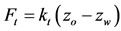 (4)
(4)
Assume the following 
 then
then ,
,  where mb and ms are the masses of vehicle body and wheel in kilograms zb and zw are the displacements of vehicle body and wheel, meters, ks and kt are the suspendsion and tire stiffness respectively in N/m, cs is the damper coefficient in N·s/m, and zo is the road input excitation, in meters.
By substituting Equations (1) and (2) in Equations (3) and (4) we get.
 (5)
(5)
 (6)
(6)
where; u is the control force from the hydraulic actuator.
By combining the equations and formulating them in a state space form, we get:

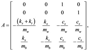
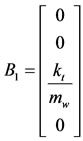 , and
, and 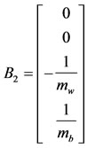
The quarter model parameters are listed in Table 1.
3. Road Excitation Model
A periodic road excitation input has been used for simulation of suspension systems. The periodic input is used for smooth road in order to evaluate ride comfort. It is widely recognized that the road surfaces approximate to Gaussian processes, having a power spectral density (PSD) of the form [17]:
 (7)
(7)
where:
Rc Road roughness coefficient.
f Road excitation frequency, Hz.
4. Robust Mixed H2/H( with Pole-Placement Controller
Noise attenuation or regulations against random disturbances are more naturally expressed in LQG or H2 terms. Besides, H¥-synthesis only enforces closed-loop stability and does not allow for direct placement of the closed-loop poles in more specific regions of the left-half plane. Since the pole location is related to the time response and transient behavior of the feedback system, it is often desirable

Figure 1. Semi-active suspension system.
to impose additional damping and clustering constraints on the closed-loop dynamics. This makes multi-objective synthesis highly desirable in practice, and LMI theory offers powerful tools to handle such problems.
Mixed H2/H¥-synthesis with regional pole placement is one example of multi-objective design addressed by the LMI. The control problem is sketched in Figure 2. The output channel z¥ is associated with the H¥ performance while the channel z2 is associated with the H2 performance (LQG aspects) [18-20].
4.1. System Representation
Figure 2 shows the standard representation of the robust output-feedback control block diagram where P(s) is the plant and K(s) represents the controller that is usually of the same order as the plant, let: