Fatigue Performance of Precast FRP-Concrete Composite Deck with Long Span ()
1. Introduction
The FRP-concrete composite deck combines FRP and concrete by placing concrete over a permanent FRP form. This deck has been developed and applied in various forms [1-4]. Such deck is dedicated to short and medium spans of which constructability and economic efficiency are improved owing to the lightweight, high strength and remarkable durability and resistance to corrosion of FRP. Especially, the FRP-concrete composite deck developed by Cho et al. [2] is lighter than other types of decks by adopting a hollow FRP panel at the bottom of the section. Such lightweight constitutes a strong advantage for bridges of which economic efficiency is sensitive to the weight like cable-stayed bridges [5].
However, differently from short to medium span decks, the deck of long-span bridges like cable-stayed bridges is disposed on cross-beams, which makes the direction of the strong axis of the deck coincide with that of the bridge’s longitudinal axis. Moreover, short spacing between the cross-beams results in loss of constructability and economic efficiency since this spacing corresponds to the span length of the deck. This explains the choice for longer deck span. Accordingly, in order to apply the deck developed by Cho et al. [2] to long-span bridges, need is not only to lengthen the span length of the deck but also to analyze the design in the case where the strong axis of the deck coincides with the longitudinal axis of the bridge. In addition, precasting of the deck is also required to improve the constructability and economic efficiency by reducing the construction period.
To that goal, a solution consisting of wrapping the whole FRP-concrete composite deck by concrete was conceived as shown in Figure 1. Such solution presents the advantage to lengthen the deck span length by reducing the shortening of the effective length caused by the haunch. Furthermore, another advantage is the possibility to apply the conventional deck connection methods used in previous precast decks like loop connection.
This study intends to investigate the fatigue performance of such precast FRP-concrete composite deck (PFC deck) for long span bridges purpose. The main factor influencing directly the fatigue performance of the PFC deck is the connection performance between FRP and concrete. Here, composition is realized by coarse sand coating and FRP connector. Coarse sand coating achieves performance near to perfect composition in the tangential (shear) direction [6], but offers practically no resistance in the normal (vertical) direction [7]. Therefore, FRP connector is adopted to compensate the verti-
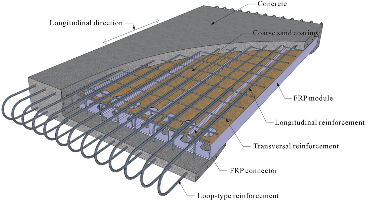
Figure 1. Basic shape of precast FRP-concrete deck.
cal resistance. Both pulsating fatigue test and rolling fatigue test are carried out as fatigue test methods. The rolling fatigue test is more conservative than the pulsating fatigue test and provides fatigue patterns similar to those observed in real decks [8].
2. Experimental Program
2.1. Specimen Details
The specimen pool includes 1 specimen for the evaluation of the static performance (DCS), 1 specimen for the evaluation of the pulsating fatigue performance (DCFP), and 1 specimen for the evaluation of the rolling fatigue performance (DCFR) as listed in Table 1. Specimen DCS is considered as the reference specimen to evaluate the behavior and performance before fatigue and is considered to allow future comparison with the fatigue specimens. The difference in the fatigue loads between the two fatigue specimens is due to the will to reflect the difference in the installation conditions of these specimens. Detailed explanation is given in Subsection 2.2.
The span length of the specimens is set to 4 m to correspond with real span lengths. The width is also set to 4 m in order to enable the deck to exhibit sufficiently bidirectional behavior. Figure 3 illustrates the cross-sectional shape of the specimens and Figure 2 shows the sectional shape at the center of the specimens. Loop connection is introduced in the precast decks for the connection of contiguous decks above the cross-beam. The FRP module is constituted by 2 cells and each cell has dimensions of about 200 mm (width) 150 mm (height). In addition, the FRP connectors are fabricated
monolithically with the FRP module. In the case where the FRP connectors are fabricated separately and bonded afterward, the fabrication becomes troublesome and the bonded interface may create week points prone to damage. Table 2 arranges the mechanical properties of the FRP module fabricated by pultrusion.
The FRP panel was fabricated at first by epoxybonding 10 FRP modules per specimen. Then, coarse sand coating was applied over the panel as shown in Figure 4. According to the work of Cho et al. (2010) [9], coarse sand coating was bonded using epoxy to achieve a distribution of 4 kg/m2 of the aggregates with grain size of 4 - 7 mm so as to develop optimal performance.
Figure 5 presents the fabrication process of the specimens: 1) assembling of rebar over the coarse sand coated FRP panel; 2) completion of the precast deck segment by placing concrete; 3) installation of the completed deck on a H-beam equipped with studs representing the crossbeam; 4) placing of non-shrinkage mortar up to the bottom of the deck; step 5) shows the connection after chipping of the interface and before placing of concrete; and, 6) completion of deck segment by placing connection concrete. The compressive strength of concrete in the