Charging of Materials Non-Metallic Used in Underground Mines Endangered by Firedamp and/or Coal Dust ()
1. Introduction
The prevalence of static electricity and related phenomena makes that the general principles selection of a material non-metallic should be based on the value parameters of resistance and the value of a designated charge transfer from the charged material non-metallic. The authors of the articles [4-6] focused on the individual electrostatic properties of material non-metallic. Already in 1967, in the work of Heidelberg [7], it is found that the presence of nonconductive composite coating on an isolation metal base can lead to a different kind of electrostatic discharge. It was originally defined as the discharge Lichtenberg, but is now better known as diffuse propagating brush discharge [8].
2. Definitions
For the purposes of this study, the following definitions apply.
2.1. Non-Conductive Material Non-Metallic
material non-metallic which of the parameters resistance exceeds values of 1.0 × 10⁹ W. Not distracted even the charge when is in contact with the ground (for example, many common plastics).
2.2. Composite Coating
dried or cured paint coating applied to the base of metal or of non-metallic. The electrostatic properties of a composite coating are dependent on the percentage of a polymer particles in the varnish [9].
2.3. Surface Resistance RS (()
the surface resistance of material non-metallic between two parallel electrodes about equal length of contact.
2.4. Resistance Volume RV (()
resistance on the two opposite faces of a non-metallic material between two electrodes through.
2.5. Charge Induced (nC)
electrostatic field generated inside the material ordered by the dipole moments of gravity move apart causing negative charge to the center of positive charge.
2.6. Charge Transfer Q (nC)
discharge of local charge induced drain into the ground with the charged material non-metallic.
3. Characteristics of Materials Non-Metallic
To study the electrostatic properties of selected natural and synthetic materials non-metallic and non-metallic products obtained from the processing of synthetic nonmetallic materials, which are widely used in underground mining [10]. Some materials have a structure of homogeneous or heterogeneous. To systematize the testing of electrostatic properties of materials are divided into five groups whose means of identification are shown in Table 1.
Electrostatic properties of materials non-metallic depend on temperature and humidity. These properties change with the aging of a material. In practice, there is an ideal materials non-metallic and the actual is characterized by a finite values of resistance.
During the selection of samples, 5 samples were prepared in the shape of a rectangle (170 × 150) mm to enable

Table 1. Distribution of materials into groups.
correct measurements. The surfaces of samples of materials were clean, unpolished or polished organic means. To ensure the unification of measurements prior to testing, the materials were clean. Then, the materials were air through aging and conditioning for 48 hours at laboratory room, at t = 23˚C ± 2˚C and relative humidity φ = 25% ± 5%. To ensure repeatability during testing, climatic conditions were the same as in the air [11]. After the material, it is subjected to air de-charging.
4. Measuring the Two Parameters of Resistance
Resistance is a basic physical parameter characterizing electrostatic properties of a materials non-metallic. The test was carried out under the same climatic conditions as the parameters temperature and humidity. The measurements were performed at a voltage of 500 V after 60 seconds within applying a voltage. After conditioning of each samples were subjected to de charging.
4.1. Measurements
To measure of surface resistance were used the electrode strips. The sample of a material was placed on the insulation board (Figure 1) so that the side of surface is designed to complete the study was directed towards to the top. Electrode strips combined with terminal of meter resistance and after the time 60 seconds from the test application of voltage recorded value of surface resistance RS.
To measure the volume resistance of a material used a set of electrodes (Figure 2). Electrodes were located on the surface of sample. The kit consists of two electrodes separated by the sample.
The surfaces contact of electrode are provided oscultion with the surface material [12]. Before each measurement, the surface samples were de charging.
4.2. Results of Measurements
In the protocol of measurements for each sample was

Figure 1. Schematic measurement surface resistance on the sample of a material.
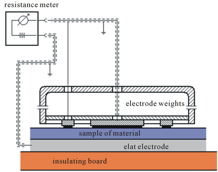
Figure 2. Schematic measurement on the sample No. 2 of volume resistance RV.
calculated the arithmetic mean value and uncertainty of a measurement and the values are given in Table 1. The study protocol for each sample provides information about conditions at the time of a survey. The collective measurements of results two parameters resistance of a materials non-metallic shown in Table 2.
4.3. Evaluation Results of Measurement
The parameters resistance examined a materials nonmetallic i.e. surface resistance RS and volume resistance RV exceed a value 1.0 × 10⁹ W. Audited types of a materials non-metallic are the properties of electricity a nonconductive, which in the conditions of use can accumulate charge induced.
5. Charging—Inducing a Charge
5.1. Introduction
Charging is the primary source of excitation causing of electrostatic charge on the surface material non-metallic [13]. To determine the effectiveness of “chargeability”, for all types charging used the other samples of material non-metallic [14]. On the neutral material non-metallic density of a charges induced related is equals zero.
5.2. Charging by Contact
In Section 5.2, the author focuses on the role of an asymmetric friction during charging by contact between the fabric and about the various construction particles in the material non-metallic. The particles of a material are the systems static [15]. Symmetry in the rubbing surface of a sample is affected by a statistical differentiate various the properties of a material or the particle size and kind of rubbing fabric [16]. Asymmetry during of a charging by contact plays an important role, since the surface contact

Table 2. Parameters resistance of a materials non-metallic.
is asymmetric considerably larger than the fabric on the stationary sample. The methodology for charging by contact, stationary surface of material non-metallic is rubbed with a fabric asymmetrically [17].
The two stages of a charging by contact:
5.2.1. Stage 1—Hand Rubbing Fabric
Ten-rubbing with a fabric sliding movement of a sample in place “Elementary catchment area of friction”. It is a sliding friction which may require movement of quasi constant force. The rubbing fabric causes the motion of electrons in atoms and nuclei of sample particles, causing momentary electric moments. The sample and the fabric are contrary charged. Between them formed the electric field. Performed rubbing fabric (Figure 3):
- the cotton (causative agent of charging);
 (a) (b)
Figure 3. Stage 1: Hand rubbing fabric the sample of a material.
- the polyamide (causative agent of charging).
where: (a): The system of materials used to the hand rubbing; (b): Section A-A: Schematic perform the hand rubbing fabric.
To the effect of hand rubbing fabric that on the surface sample is generated charge induced Qi.
5.2.2. Stage 2—Manual Lifting Charged Sample
Careful separation the charged sample located on the plate. At the separation is involved the friction and the work is done to overcome the attraction of the opposite charges on the sample and the plate. Charge Q0 generated by charged sample separation can reach hundreds of nano-coulombów.
As a result of the separation on the charged sample accumulates additional charge Q0 (figure 4).
In the process generating of charge induced on the sample QS is the sum of charges caused by the friction Qi and charges Q0 caused by separation from the plate [18]. The principle superposition of charges express their additivity feature. The total value of a charge induced QS can be expressed by the formula (1):
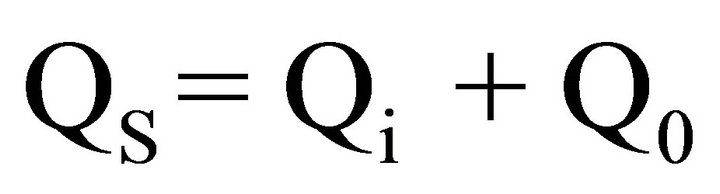 (1)
(1)
charging by contact repeated 10 times.
5.3. Charging by Influence
Charging the surface of a sample is the result of ordering the direction of an electric field causing almost permanent displacement or reorientation of an atomic or molecular structure of a material. Under the influence of a field the material non-conductive is polarity and on them surface appearing charges about to specific density s. These charges produce a field in the interior of the material expressed by the formula (2) with intensity EW:
 (2)
(2)
The permittivity e of a material indicates how many times the electric field EW inside of them is weaker than the field E0 on the outside.
Sample of a material is a heterogeneous material non-metallic placed in an isotropic inhomogeneous elec-
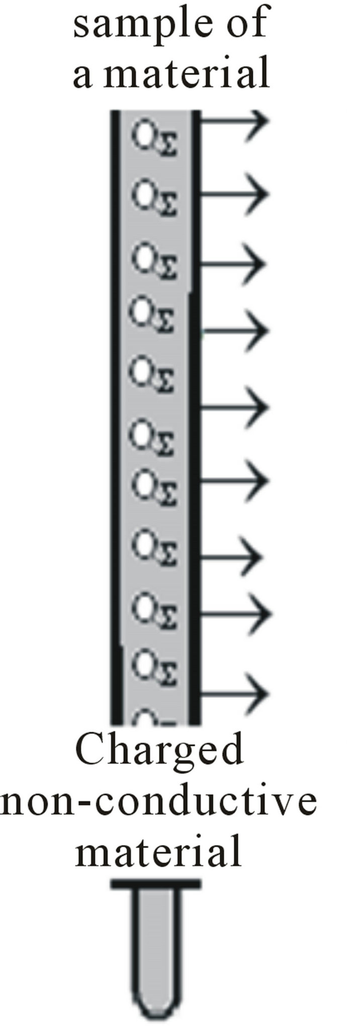
Figure 4. Stage 2: Charged material raised to the vertical position.
tric field.
The two stages of a charging by influence:
5.3.1. Stage 1: Charging by Influence
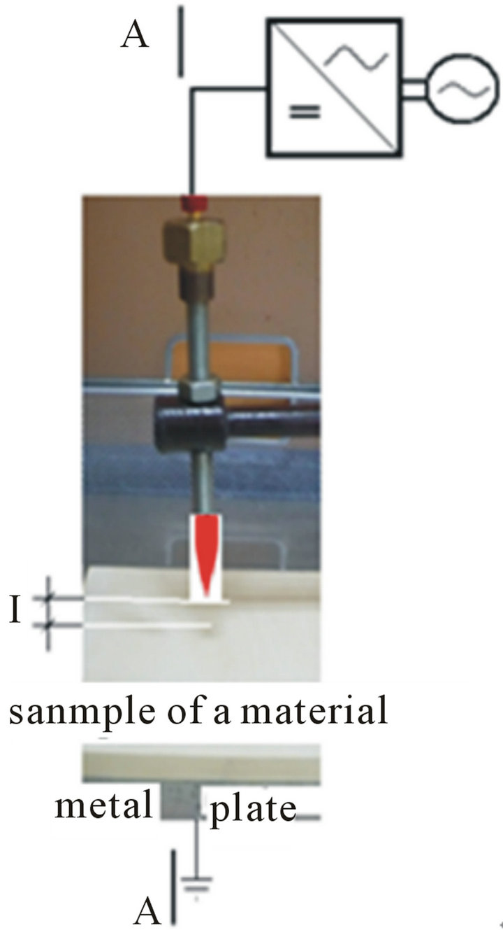
Surface of material were temporary non-uniform electric field effects emitted from the barbed electrode. At a distance of l = 30 mm above the sample (Figure 5) was placed barbed electrode that is connected to the power supply voltage set at 30 kV.
where: (a) location barbed electrodes on the sample; (b) section A-A: scheme of a charging by influence.
Polarization P of a material is directly proportional to the intensity of E.
5.3.2. Stage 2
The effect of charging by influence is the charge QS distributed unevenly over the entire surface of a material (Figure 6). Resultant moment dipole of non-conductive material is becomes different from zero. The collection called the field lines vectors creates an electric field of a vector field strength Equation (3).
 (3).
(3).
A field in a material non metallic is a superposition of a fields Eobc produced by the charges foreign and a fields EW produced by charges related by the formula (4).
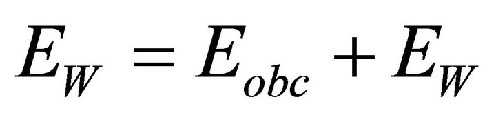 (4).
(4).
The charged sample located on the plate at time t = 0 s around the charged material is the electric field (Figure 6).
Before proceeding to the next charging the surfaces charged of material were de charging.
6. Determination the Charge Transfer
Process charging apparently takes place in such a way that the charges positive and negative if it were associated with
 (a)
(a) (b)
(b)
Figure 5. Stage 1: The sample of a material is located on the plate in the electric field.
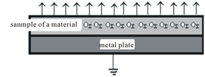
Figure 6. In the space above the charged material is not homogeneous field.
elastic forces [19]. In any isotropic non-conductive material charged varied spontaneous and sometimes.
6.1. Charged Material—Charge Induced
The charge produces an electrostatic field covers an area of enclosed equal charge induced QS on that surface. The charge induced changes the space around it creating a field. The field of a charged material is at the same time the notion model and physical reality (Figure 7).
6.2. Local Drainage of Charge Induced—Measuring Method
The charge produces an electrostatic field covers an area equal to the closed charge induced QS on it. Charge induced changes of space around it to produce the field. The field of a charged material is at the same time the notion of a model and a physical reality (Figure 7).
In the measurement method associated with the disposal of charge induced by the charged material listed stages 3 and 4:
6.2.1. Stage 3: Approximation Electrode
In order to discharge to the local center of a charged material slowly approached the collecting electrode ball about a radius of 15 mm (Figure 8).
6.2.2. Stage 4: Local Discharge
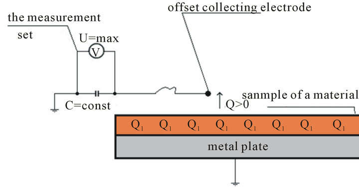
When the distance between the collecting electrode from the charged material converges to zero, at the time t = 0 + s the measurements drop of voltage U = max at the ca pacity of a capacitor C = const (Figure 7).
 (a)
(a) (b)
(b)
Figure 7. Time t > 0 + s: Measuring the drop of voltage caused by the local discharge with the charged material. (a): sample of a material raised to the vertical; (b): Sample of a material located on the metal plate.
 (a)
(a) (b)
(b)
Figure 8. Time t £ 0 s: Free approaching the collecting electrode to the charged material.
Local discharge with the charged material collecting electrode (Figure 7) causes a temporary increase the drop of voltage for the instantaneous value of extreme U = max.
The measurement should be repeated 10 times each time after charging.
6.3. Determination of a Charge Transfer Q
Determination of a charge transfer Q harvested from the charged material by (5):
 (5)
(5)
where:
C (nF)—the reference of capacitor;
U (V)—voltage (measured maximum value).
In the Table 3, it shows the maximum values are determined the charge transfer as resulting from the 10 measurements. These values form as series of detailed, containing the value of a charge transfer designated on the tested materials non-metallic.
Included in the Table 3, figures designated charge transfer form one guild the number of statistical. Assigned the numerical values designated of a charge transfer do not take intermediate values are a measurable of a present discrete feature number. The whole number of statistical

Table 3. The number of values assigned to specific charges transfer.
are divided into three classes as a function of an agent causing charging appropriately labeled Q1, Q2, Q3 (designated charge transfer). This number is a number of detailed structured solely determined by the value of a charge transfer, which takes the form of a number disordered. The measurements properties of electrostatic often need not be very accurate. In many instances, administration of the values fall within the specified range of values is sufficient, particularly in the study of control process. It is important, however, certainty and confidence that the measurements parameters of a resistance are performed correctly. Presented the methods concern more accuracy to ensure repeatability than ensuring high accuracy.
Presented the results of a designated charge transfer does not include information about the location of errors caused by non-uniform charge induced on a charged materials non-metallic and their impact on the value of a designed charge transfer Q. In [20], the authors show that measuring the voltage drop across the capacitor with constant volume using unshielded spherical electrodes can be dealt with by applying a correction factor in the range of 2 to x2.5. To assess susceptibility to the chargeable of a tested materials non-metallic used the criterion by [3 c. D.4.2.4].
6.3.1. Positive Result
If the maximum value of a designated charge transfer from the charged material non-metallic satisfies the condition (6):
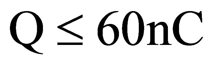 (6)
(6)
The material does not pose the risk of explosion from the static electricity in group I (safety in methane atmospheres explosive) and group III (safety against dust atmospheres explosive) [21]. Therefore, it can be assumed that the tested material is suitable for use in underground mining hazards of explosive methane and/or coal dust.
6.3.2. Negative Result
If determined the maximum value of a charge transfer (7):
 (7)
(7)
it this material may not be intended for use in underground mines endangered by firedamp and/or coal dust. The nonconductive material non-metallic can be an effective source of static electricity and pose the risk of explosion in the underground mine workings.
6.4. Grouping of Statistical
The aim grouping of statistical is clustering to identify similarities and differences charge transfer in the test set of non-metallic materials and to formulate proposals obligatory. In the collection of non-metallic materials of a number i = 20 common feature is the accumulation of charge induced and features a variety are generated of charge transfer. Generated charge transfer is forming the guild variable of a displacement one the feature series of statistical [22].
The relative values of a charge transfer as random real numbers are grouped in the table 4 into one of three column the classes of collective. The relative value of a charge transfer qwx determined by the formula (8):
 (8)
(8)
where:
Qi (nanoCoulomb)—designated the maximum value of charge transfer.
Q = 60nC—extreme value of a safe charge transfer.
6.4.1. Comment
Detailed in a series three classes of collective:
qwb—the relative value of a charge transfer after charging by contact (rubbing of a cotton cloth);
qwp—the relative value of a charge transfer after

Table 4. The one feature series of statistical the relative values of a charge transfer qwx the three classes of collective.
charging by contact (rubbing of a polyamide fabric);
qwu—the relative value of the charge transfer after charging by influence.
Criteria of evaluation:
qwx £ 1—the material non-metallic “non-chargeability” as a result of a particular type of charging;
qwx > 1—the material non-metallic “chargeability” as a result of a particular type of charging.
The span class of collective ranges of a values:
- for qwp—open interval of real numbers on the ends of a qwpa = 0.015 and qwpb = 3.0 as {qwp: qwpi < 3.0;
- for qwb—open interval of real numbers on the ends of a qwpa = 0.177 and qwpb = 4.0 as {qwp: qwpi < 4.0;
- for qwu—open interval of real numbers on the ends of a qwpa = 0.025 and qwpb = 11600.0 as{qwp:qwpi < 11600.0.
6.4.2. Conclusions
1) In the collection of a number 20 tested non-metallic materials relative value of a charge transfer:
- qwx £ 1 i.e. 3 material non-metallic “non-chargebility” this is 15 % the tested collection does not generate dangerous charge transfer over 60 nC;
- qwi >1 i.e. 17 material non-metallic “chargebility” this is 85 % the tested collection generate dangerous charge transfer over 60 nC. The material non-metallic “chargebility” should not be used in underground mining risk of an explosion methane and coal dust.
2) In the 3 classes of collective contains n = 60 numbers of real qwx the relative value of a charge transfer. For 25 the values numbers of real qwx > 1, or 41.67%, does not meet the requirements for protection against static electricity to methane.
3) In the classes of collective qwb registered 10 values qwb > 1.0 or 50% the tested materials non-metallic by charging by contact (rubbing of a cotton cloth) can generate dangerous charge transfer.
4) In the classes of collective qwp registered 1 value or 5% the tested material non-metallic by charging by contact (rubbing of a cotton cloth) can generate dangerous charge transfer.
5) In the classes of collective qwu registered 15 values qwb > 1.0 or 75% the tested material non-metallic by charging by influence can generate dangerous charge transfer.
Popularly published tables describing the properties of materials non-metallic do not contain any information about the properties of electricity. The spark discharge of electrostatic able to ignition the atmosphere potentially explosive [23] correlates with the value of a charge transfer from the charged material with probability greater than zero.
The value of a charge transfer Q can be used to the risk the analysis for the safe use the parts or the components of non-metallic that in the conditions of use, are exposed to charging such as fuel systems for motor vehicles, which are exposed to continuous charging [24].
At the end of this article imposes a simple question:
Do you know the value surface resistance and volume resistance of non-metallic material lets make a theoretical estimate expected the value of a charge transfer from the charged material?
7. Conclusions
Results of this study show that:
Protection against static electricity is based on standardized test methods, in which many people seem to be too stringent.
To ensure repeatability during testing climatic conditions, temperature and humidity of a room laboratory were thoroughly established [25].
The standard for measuring parameters of resistance, the materials and products of non-metallic should be an important element in any conformity assessment system.
The measurement control of surface resistance of the material non-metallic should be an important step to ensure the safety of a process.
The parameters of resistance examined the materials non-metallic exceeding the value 1.0 × 10⁹ W. The materials belong to the group about electrostatic properties of nonconductive.
On the macroscopic surface of charged material nonmetallic, base met field theory [20].
Charging by contact or rubbing asymmetric, causes the transfer of electrons (and sometimes ions) between the slider and the sliding materials. This is a method for the preparation of charge induced on the surface of material non-metallic. [19]
After charging by influence, the charge transfer of charged composite coating on a metal substrate is greater than 150 nC (~200 nC). The operating conditions tested composites coating may pose a risk of explosion [17].
In order to explicitly exclude the impact parameters on air of temperature and humidity to change the electrostatic properties of a material non-metallic, in places where potential atmosphere happens, ambient parameters of climatic should be recorded [18].
Methods for determining the charge transfer from the charged material non-metallic should be widely supported and used in analysis of risk.
The most effective means to prevent the discharge of electrostatic is to prevent the accumulation of electrical charge on the non-conductive materials non-metallic [22].
If the design of a device does not rule out the possibility of hazards ignition from the discharge of electrostatic, this device should be equipped in the warning label.