Plastic Deformation Mechanisms of Base Material and Friction Stir Welded AZ31B-H24 Magnesium Alloy ()
1. Introduction
The deformation mechanisms of pure magnesium are well known and are discussed in many publications, such as [1-3]. Researchers in the field agree that plastic deformation occurs on basal slip systems at room temperature, while at temperatures higher than 225˚C, prismatic and pyramidal systems become active as well. This in turn dictates relatively low elongation-to-fracture of pure magnesium up to about 225˚C. Since AZ31 (Al 3%, Zn 1%), on the contrary, exhibits large elongation-to-fracture (around 15%) even at room temperature [4], different operative deformation mechanisms can be expected. A few studies deal with the plastic deformation mechanisms of AZ31 (Al 3%, Zn 1%). Some of the proposed models are summarized below:
Bussiba et al. [5] performed tensile tests at different strain rates on AZ31 at 177˚C. The elongations they obtained varied from 90% to 120%. They referred to grain boundary sliding [GBS] as a prevailing deformation mechanism.
Ben Hamo et al. [6] studied the microstructural changes of AZ31 after severe plastic deformation by Equal Channel Angular Extrusion (ECAE) at 350˚C by means of optical microscopy, Scanning Electron Microscopy (SEM) and Transmission Electron Microscopy (TEM). They pointed to an increase in dislocation density and the occurrence of dynamic recrystallization. Jin et al. [7] studied ECAE of AZ31 at 225˚C and noticed continuous dynamic recovery and recrystallization during ECAE. Dislocations were reported to form dislocation boundaries, which afterwards evolved to lowand high-angle grain boundaries.
Kim and Kim [8] conducted four stages of ECAE. The first and second stages were conducted at 320˚C, while the third and fourth stages were conducted at 250˚C and 200˚C, respectively. They reported grain refinement from 48 μm to 2.5 μm, as well as a bimodal grain size distribution after the first stage together with twinning and high dislocation densities after four stages of ECAE at 200˚C - 320˚C.
Tian et al. [9] performed creep tests of AZ31 at 200˚C and proposed dislocation slip on basal and non-basal planes, together with twinning combined with dynamic recrystallization as the main deformation mechanisms. With respect to the active slip systems, they based their conclusion on contrast TEM investigation, namely, the  invisibility criterion.
Liu et al. [10] studied the deformation behavior of AZ31 during tension at the temperature range of 100˚C - 250˚C and at the strain rate range of 10−3 - 10−1 s−1. They claimed that when the temperature was below the recrystallization temperature, twinning and dislocation slip— both basal and non-basal—were the dominant deformation mechanisms, while at temperatures above the recrystallization temperature, twinning-induced dynamic recrystallization (DRX) occurred as well.
Koike et al. [11] studied fatigue behavior at room temperature in tension cycles. They concluded that both twinning and prismatic slip contribute to the deformation.
Somekawa et al. [12] studied the creep properties of AZ31 at the temperature range of 200˚C - 350˚C. Calculation of stress exponent and activation energy led them to the conclusion that the major deformation mechanism is climb-controlled dislocation creep, which is controlled by pipe diffusion at low temperatures and by lattice diffusion at high temperatures.
Tan and Tan [13] focused on the occurrence of DRX in the case of AZ31B-O during tension tests at elevated temperatures, at the range of 200˚C - 400˚C. They witnessed grain refinement via deformation, mostly at 250˚C. This grain refinement was attributed to dynamic continuous recrystallization, which involves progressive increase in grain boundary mis-orientation and conversion of low angle boundaries into high angle ones. Having conducted a TEM study, they reported on cells of tangled dislocation walls that are converted to a subgrain structure.
Watanabe et al. [14] referred to the high ductility of 196% exhibited by AZ31 during tension tests at 371˚C. For their study they used coarse-grained (130 μm) commercial rolled AZ31 sheet. They pointed to glide control dislocation creep as the major deformation mechanism.
Mwembela et al. [15] conducted hot torsion tests in the temperature range of 180˚C - 450˚C. Having calculated the activation energy, they claimed that these values were consistent with the occurrence of rising dynamic recovery at 180˚C - 300˚C that in turn contributes to ductility improvement. According to Mwembela et al. [15], dynamic recrystallization was initiated at about 300˚C and 0.1 s−1 and became more widespread and characterized by larger grains as the temperature rose and the strain rate declined. They added that DRX was generally found near the grain boundaries, but nevertheless seemed sufficient to markedly improve ductility.
Myshlyaev et al. [16] conducted hot torsion tests from 180˚C to 450˚C and from 0.01 to 1.0 s−1 together with a TEM study. They reported on twins at 180˚C with individual dislocations, with Dynamic Recovery (DRV) assumed to take place due to the existence of serrated grain boundaries. Deformation twins were detected at 240˚C. as well together with higher dislocation density. Polygonal subgrains were observed at 300˚C with walls of regularly arranged dislocations and random internal neworks. Equiaxed grains, smaller than the initial ones, were recorded at 360˚C and higher. In addition to the deformation mechanisms briefly mentioned in the preceding paragraphs, it seems that most of the authors agree regarding the role of DRX at high temperatures. Assuming, however, that DRX is expected during FSW due to the high temperatures and the heavy plastic deformation, the current study focuses on the deformation process in a prerecrystallized structure at relatively low temperatures.
2. Experimental
The material used in this study was a commercial AZ31B-H24 magnesium alloy, with a nominal chemical composition of Mg-3.0Al-1.0Zn (wt%) in the form of 3.175 mm thick 200 × 100 mm plates. The plates were butt welded using a CNC milling machine. An H-13 steel FSW tool was used, consisting of a pin 4.5 mm in diameter and 3 mm high, and a 20 mm diameter shoulder. The welding parameters were a rotational speed of ω = 2000 rpm and a transverse speed of . All the welded specimens were radiographically checked prior to preparation of the creep specimen. Creep specimens were prepared with their longitudinal axis perpendicular to the seam, so that each specimen contained the welding nugget, the HAZ, the TMAZ and the parent material. Optical metallography was conducted with the aid of a Zeiss AZ10 optical microscope, while an FEI Inspect Scanning Electron Microscope (SEM) equipped with an INCA electron probe micro-analyser was used for SEM metallography. Creep tests both of parent AZ31-H24B material and of welded specimens were conducted at temperatures of 100˚C, 200˚C and 300˚C and in the load range of 10 - 150 MPa. Specimens that underwent creep were used for a TEM study. TEM investigation involved using an FEI Titan 300 kV highresolution TEM (HRTEM) and a Tecnai G2 T20 200 kV TEM. The specimens for the TEM study were taken from the neck of the broken creep specimen, tested at 100˚C and 50 MPa, as close as possible to the fracture surface. TEM study of the base material was carried out on an AZ31B-H24 non-welded specimen that had crept at 100˚C under 50MPa for 1215 hours up to an elongation of 5% without being broken, namely, an interrupted creep test specimen. A TEM approach simpler than the conventional
  investigation was used in this study, as used by Regev et al. [17] for an AZ91D dislocation study. The samples were tilted into zone axes related to basal planes parallel to the incident electron beam, such as
 . With these zone axes, dislocations on basal planes should appear straight and parallel, while their orientation (which is the orientation of the basal planes) can be obtained from the diffraction pattern. It should be emphasized that the active slip systems or the exact Burgers vector of the dislocations cannot be determined with this approach. Nevertheless, it provides evidence for the existence of non-basal dislocation segments.
3. Results
Optical micrographs of the various zones in the vicinity of the welding are given in Figure 1. The parent metal (Figure 1(a)) is characterized by a bi-modal grain size distribution, while grain coarsening is discernible in the Thermo-Mechanically Affected Zone (TMAZ), as can be seen in Figure 1(b). The grain size of the Heat Affected Zone (HAZ) is relatively uniform (Figure 1(c)), though coarser than the fine grains of the parent metal. The grains of the nugget zone (Figure 1(d)) look deformed to some extent. Their size is uniform and finer compared with the parent material. Twinning can be observed in each zone, including the parent material. An SEM micrograph of the parent material under higher magnification is depicted in Figure 2. EDS analysis of ten bright particles, such as those indicated by arrows in Figure 2, showed that the particles contained a large amount of Mn, between 32.03 wt% and 54.45 wt%. No other phases were detected.
An optical micrograph of a broken creep specimen, which was taken from its neck next to the fracture line, is shown in Figure 3. This specimen had crept under 150 MPa at 100˚C, and the load had been applied horizontally. It can be seen that its grains are elongated and heavily twinned.
The elongations-to-fracture of non-welded AZ31 specimens varied between 24.6% and 53.7%, while the elongations-to-fracture of the welded specimens varied between 5% and 14%, with one exceptional specimen for which the recorded elongation was higher than 35%. As for the creep tests at 100˚C, the elongations-to-fracture varied from 24.6% to 41.9% in the case of the nonwelded specimens, and from 5% to 10% for the welded specimens. According to the TEM procedure described in the previous section, basal (B) and non-basal (NB)

Figure 2. An SEM micrograph of the parent material.
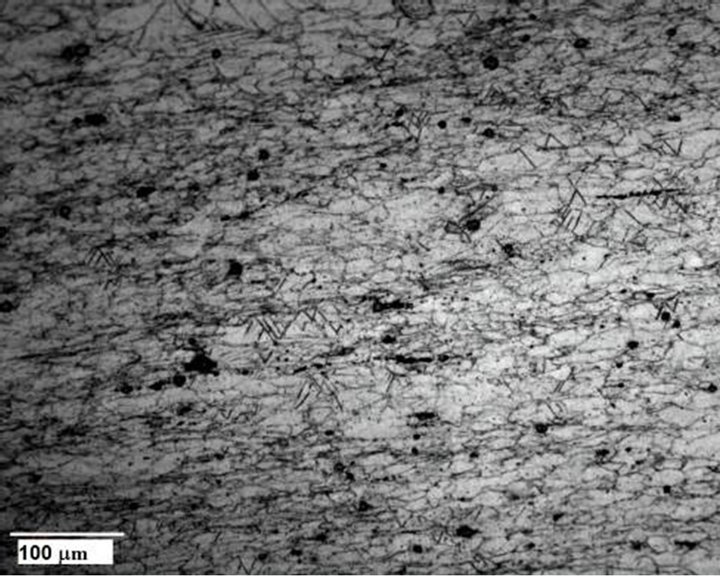
Figure 3. An optical micrograph of a broken creep specimen.
dislocation segments were observed in the welded specimen, as can be seen in Figure 4. Bright field (BF) TEM images taken from the welded crept specimen at  are shown in Figure 4. A dislocation array can be seen in Figure 4(a). This array lies partially on the basal plane. However, each of its dislocations contains non-basal segments. Non-basal dislocation segments together with basal segments are shown in Figure 4(b), while Figure 4(c) shows the respective selected area diffraction pattern. In order to isolate the influence of the welding process, the same TEM procedure was repeated on a non-welded specimen that underwent creep for 1215 hours at 100˚C under 50 MPa, as shown in Figure 5. It can be seen that most of the dislocation segments lie on the basal planes, both in the welded and in the nonwelded specimens (Figures 4 and 5 respectively).
For the sake of comparison, Figure 6 was taken from the non-welded specimen that underwent creep for 1215 hours at 100˚C under 50 MPa at  zone axis in which the basal planes are inclined with respect to the incident electron beam and are therefore projected at the BF image. It can be clearly seen that the distribution of the dislocations is homogenous, namely, no planes are preferable for dislocation glide.
4. Discussion
Optical metallography shows that the bi-modal grain size microstructure of the parent material underwent extensive grain coarsening at the TMAZ. The grain size distribution of the TMAZ varies from a few microns to hundreds of microns, as can be seen in Figure 1. The HAZ, in contrast, is characterized by a relatively uniform grain size. The finer and relatively uniform grain size of the nugget can be attributed to DRX. The large differences in the average grain size probably influence the mechanical properties of each zone. Both this point and the existence of twinning at each zone, including the
parent material, will be discussed in the following paragraphs.
The expected phases according to the Mg-Al phase diagram [18] are Mg and β (Mg17Al12), and the chemical composition of the AZ31 alloy is within the two-phase region in which the Mg and β (Mg17Al12) phases coexist. The existence of these two phases was also reported in the literature by a number of researchers [5,9,15]. However, in this study no β phase was detected by EDS analysis. The only phase recorded besides the Mg matrix was the Mn-rich sub-micron particles. These results are in line with those reported by Ben Hamu et al. [6], who also did not detect a β phase and who identified the Mn-rich particles as Al8Mn5. It should be mentioned that the current study did not focus on phase characterization, and therefore X-ray Diffraction (XRD) was not performed. A possible explanation for the inability to detect the β phase is the low content of Al and hence of the β phase. Before referring to the operating plastic deformation mechanisms, the stability of the microstructure during creep should be examined. Unstable microstructure may lead to different creep behavior. This question was studied in the past by Regev et al. [19], who found that in the case of AZ91D alloy, the precipitation process of secondary β (Mg17Al12) occurring during creep influences the creep properties. The mechanism of this secondary β phase precipitation has been explained in detail elsewhere [20], and the reader is referred to this publication for a comprehensive discussion. It will only be mentioned here that secondary precipitation requires the formation of eutectic (supersaturated solid solution), while in the case of AZ31, according to its phase diagram [18] no eutectic structure is expected.
Figure 7 plots the minimum creep rate as a function of the applied stress for the base metal and the FSW samples tested at 100˚C, 200˚C and 300˚C. The welded