2. Composition, Operation Principle and Trajectory
In this study, the multiple composite piezoelectric motor is made by the multiple composite piezoelectric stator, rotor, preload adjusting module and shaft, shown as Figures 1-3. In which the multiple composite piezoelectric stator is composed of the base, the first actuating element, the second actuating element and stator, shown as Figure 3. In addition the preload adjusting module includes the limiting element, spring, washer and nut. As for the first actuating element is composed of the longitudinal vibration module and the first bending vibration module (which the first bending vibration module includes the horizontal bending vibration module and the vertical bending vibration modules), shown as Figures 3-4. And the second actuating element or bending vibration module (which the second bending vibration module includes the horizontal bending vibration module and the vertical bending vibration modules), shown as Figure 3 and Figure 5. Finally, we can found the motion trajectory or behavior of the multiple composite piezoelectric stator or motor, when we applied different driving voltage, frequency and phase angle to the actuating elements. In particular, we can find an elliptical trajectory occurs at the top or free end of the stator, shown as Figures 6-7. The approximate solution of the elliptical trajectory can be expressed as [31] [33] :
 . (1)
. (1)

Figure 1. The composition of the multiple composite piezoelectric motor.

Figure 2. The cutaway view of the multiple composite piezoelectric motor.

Figure 3. The exploded view of the multiple composite piezoelectric motor.

Figure 4. The operation principle of the 1st actuating element (Which it includes the Longitudinal Vibration Module_LVM and 1st Bending Vibration Module_1st BVM).

Figure 5. The operation principle of the 2nd actuating element (So called the 2nd Bending Vibration Module_2nd BVM).

Figure 6. The operation principle of the multiple composite piezoelectric stator.

Figure 7. The operation principle of the multiple composite piezoelectric motor.
Where
 . (2)
. (2)
 . (3)
. (3)
 . (4)
. (4)
And
 . (5)
. (5)
 . (6)
. (6)
 . (7)
. (7)
where u, v, and w represents the vibration displacement of the horizontal, vertical and longitudinal direction separately. And where Um, Vm and Wm represents the vibration amplitude in different direction separately.  represents driving angle velocity, where fm representatives driving frequency. And
  driving phase angle (such as 0˚ - 180˚). Where cxi, cyi and czi represents the constant coefficient tensor in different direction separately, and where the subscript i = 1, 2, 3. d3i represents constant piezoelectric strain of d-form. Such as d31, d32 and d33.
3. Simulation and Experiment
We choose five different sizes of the multiple composite piezoelectric motors or stators to simulate by convention in order to compare with the previous papers [1] -[33] or [31] [33] , shown as Figures 8-9 and Table2 Wherein the base and stator is made of copper and aluminum separately. Which the first actuating element is made of PZT and copper slices. And the second actuating element is directly attached to the side of the stator by the PZT under different polarization direction, shown as Figure 6. As for the physical properties of the multiple composite piezoelectric stator is expressed in Table3

Figure 8. The prototype of the multiple composite piezoelectric motor.

Figure 9. The prototype of the #1 - #5 multiple composite piezoelectric stators.
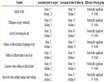
Table 2. The net weight and size of multiple composite piezoelectric stator.
Table 3. The physical properties of multiple composite piezoelectric stator.
We use the ANSYS code to simulate in this study. And the simulation procedure includes modeling (show as Figure 10), meshing (show as Figure 11), solving and post-processing. We choose the element type of solid 98 for all materials in modeling operation process. We choose the number 6 - 10 of smart size for all materials in meshing operation process. The mechanical boundary condition is set to clamped-free. As regards the electrical boundary conditions is set to open circuit (That is Vin = 0 or Vp-p = 0.) and closed circuit (That is Vin = 100 - 180 Vp-p or Vp-p = 100 - 180 Vp-p) for all piezoelectric materials in solving operation process.
In this experiment, we used two sets of the dual channel arbitrary function generator (Model: A-303, AA Lab. Systems Ltd. Co.) and four sets of the power amplifier (Model: AFG-3022, Tektronix Co.) to control or drive the multiple composite piezoelectric motor. In addition, we used the digital tachometer (Model: RM-1501, TES Electrical Electronic Co.) and the sound level meter (Model: TES 1350A, TES Electrical Electronic Co.) to measure the rotational speed and noise of the multiple composite piezoelectric motor separately. Furthermore, we are using the mass or rotor with two different materials to test the loading ability of the multiple composite piezoelectric motor, shown as Figure 12.
4. Results and Discussion
According to the results of simulations by the ANSYS code and experiments, we found:
1) The resonance frequency is inversely proportional to the length of the multiple composite piezoelectric stator. Wherein the first resonance mode frequency is 9.174 kHz of the #1 multiple composite piezoelectric stator. And the first resonance mode frequency is 7.565 kHz of the #5 multiple composite piezoelectric stator, shown as Figure 13.
2) The maximum deformation is inversely proportional to the length of the multiple composite piezoelectric stator. The maximum deformation and best vibration modes which appear in 38 - 39 kHz or the seventh vibration mode for the #1 - #5 multiple composite piezoelectric stator, shown as Figures 14-19.
3) The maximum rotational speed is inversely proportional to the length of the multiple composite piezoelectric motor. The #1 multiple composite piezoelectric motor has a maximum rotational speed of 600 rmp under conditions of 180 V-p- driving voltage, 37.8 kHz driving or resonance frequency, 00 driving phase angle and 12.1 gw loading. It is 1.25 and 3.0 times of the maximum rotational speed for the rod type ultrasonic motor [31] and the composite type piezoelectric motor [33] , shown as Figure 20.
4) The noise range is between 60 and 100 dB of the multiple composite piezoelectric motor, where the higher noise appears before 20 kHz. And the noise values are independent of the driving frequency, shown as Figure 21.
5) The conversion efficiency of direction of the multiple composite piezoelectric motor is inversely proportional to the length of stator. Wherein the best conversion efficiency of direction is the #1 multiple composite

Figure 10. The modeling operation process of the #1 multiple composite piezoelectric stator in the simulation procedure.

Figure 11. The meshing operation process of the #1 multiple composite piezoelectric stator in the simulation procedure.
piezoelectric motor. In addition, we also the poor conversion efficiency of direction is the rod type ultrasonic motor [31] , shown as Figure 22.
6) The rotational speed of the multiple composite piezoelectric motor is proportional to the driving voltage. On average, the rotational speed of the multiple composite piezoelectric motor is higher than the rod type ultrasonic motor and the composite type piezoelectric motor, shown as Figure 23. Moreover, according to the experimental results shown in Figure 23, we can find a linear relationship between rotational speed and driving voltage. As:
 (8)
(8)
where x, y represents the driving voltage and rotational speed respectively. In addition, the constants of ai, bi represent the slope and intercept of different type piezoelectric motors, shown as Table4
7) And rotational speed of the multiple composite piezoelectric motor is inversely proportional to the loading ability under the same driving conditions. Which has a maximum loading ability is the #1 multiple composite piezoelectric motor which is 2500 gw, shown as Figure 24. Where the loading ability of the multiple composite piezoelectric motor is 1.68 and 1.08 times of the maximum rotational speed for the rod type ultrasonic motor and the composite type piezoelectric motor.

Figure 12. The experimental structure of the multiple composite piezoelectric stator.
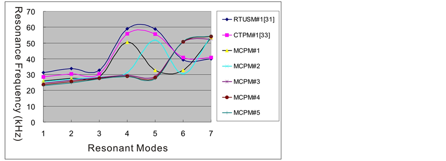
Figure 13. The driving frequency relative to the resonant modes of the #1 - #5 multiple composite piezoelectric stator.

Figure 14. The maximum deformation relative to the resonant modes of the #1 - #5 multiple composite piezoelectric stator.

Figure 15. The best vibration mode of the #1 multiple composite piezoelectric stator.

Figure 16. The best vibration mode of the #2 multiple composite piezoelectric stator.

Figure 17. The best vibration mode of the #3 multiple composite piezoelectric stator.

Figure 18. The best vibration mode of the #4 multiple composite piezoelectric stator.

Figure 19. The best vibration mode of the #5 multiple composite piezoelectric stator.

Figure 20. The rotational speed of different type motors relative to the driving frequency under conditions of 180 Vp-p driving voltage and 12.1 gw loading.

Figure 21. The noise of different type motors relative to the driving frequency under conditions of 180 Vp-p driving voltage and 12.1 gw loading.

Figure 22. The rotational speed of different type motors relative to the driving phase angle under conditions of 180 Vp-p driving voltage and 12.1 gw loading.

Figure 23. The rotational speed of different type motors relative to the driving voltage under conditions of 180 Vp-p driving voltage and 12.1 gw loading.

Figure 24. The rotational speed of different type motors relative to the loading under condition of 180 Vp-p driving voltage.
Table 4. The slope and intercept of different type piezoelectric motors.
5. Conclusion
In this study, we found that the multiple composite piezoelectric motor has better rotational speed, conversion efficiency of direction and loading ability relate to the previous similar type’s motor under the same driving conditions. The most special, when we use the multiple vibration modes to drive the motor, so that the above functions and efficiency achieve significant improvement and upgrade. Especially the maximum rotational speed of the multiple composite piezoelectric motor is 1.25 and 3.0 times of the composite type piezoelectric motor and the rod type ultrasonic motor respectively. Furthermore, the maximum loading ability of the multiple composite piezoelectric motor is 1.08 and 1.68 times of the composite type piezoelectric motor and the rod type ultrasonic motor respectively under conditions of the same driving voltage and loading or preload.
Notes
CTPM: Composite Type Piezoelectric Motor.
MCPM: Multiple Composite Piezoelectric Motor.
LVM: Longitudinal Vibration Module or Mode.
1st BVM: the first Bending Vibration Module or Mode.
2nd BVM: the second Bending Vibration Module or Mode.
MVM: Multiple Vibration Module or Mode.