Development of Optimal Structural System for Hybrid Cable-Stayed Bridges Using Ultra High Performance Concrete ()
1. Introduction
Recently, the construction market of long-span bridges in Korea has been boosted owing to the change in the land development paradigm. However, the Korean technological level related to long-span bridges remains still immature resulting in a strong reliance on advanced countries’ core technologies for the construction of longspan bridges. Therefore, need is to implement R&D dedicated to long-span bridges to prevent further outflow of the national wealth and reduce the national budget expenditure.
In the case of cable-stayed bridge as one of the representative types of long-span bridges, concrete cablestayed bridges are known to be economically efficient for main spans running between 200 m and 400 m but can also be economically competitive in various aspects for spans longer than 400 m according to the selective exploitation of the materials. The construction of an economically efficient long-span bridge is primordially relying on the reduction of the weight. To that goal, considerable solutions can be reducing the weight of concrete itself or achieving lightweight structure by the reduction of the size through the use of concrete with higher strength. To date, efforts have been ceaselessly exerted to develop lightweight concrete to reduce the weight of concrete itself and applications on structural members are being under consideration. Besides, for the solution using concrete with higher strength, the Korea Institute of Construction Technology has secured original technology related to ultra high performance concrete (UHPC) with 200 MPa-class compressive strength and durable lifetime of 200 years [1-3]. However, the application of the developed UHPC to hybrid cable-stayed bridge is subordinated to the overcoming of the generally recognized limitations of concrete cable-stayed bridges, which have been rarely applied in Korea, together with the establishment of practical technologies of UHPC. To complicate this situation, the absence of cable-stayed bridge erected using UHPC wherever in the world necessitates the development of sectional shapes and structural systems fitted to UHPC for the application of this new material to the complex cable-stayed bridge structure and the establishment of component technologies and integrated technology enabling to secure structural safety and economic efficiency.
As a cable-stayed bridge having its main structural members made of UHPC with compressive strength of 200 MPa and durable lifetime of 200 years, the hybrid cable-stayed bridge system to be developed in this study is an innovative cable-stayed bridge system providing reduction of each the construction and maintenance costs by 20% compared to the conventional concrete cablestayed bridge by improving significantly the weight and durability of the bridge. Therefore, detail design is carried out considering a real 800 m cable-stayed bridge to derive the optimal structural system of the hybrid cablestayed bridge. Thereafter, the so-derived optimal system is checked for each construction stage and its stability is verified so as to develop the technology for UHPC cablestayed bridge.
2. Derivation of the Optimal Structural System for the Hybrid Cable-Stayed Bridge
This study developed the optimal structural system for the reduced-cost and long-life hybrid cable-stayed bridge with main span 800 m using UHPC in order to construct original and economically efficient long-span bridges relying on our domestic technology.
The structural parameters influencing the performance of a cable-stayed bridge are more diversified than those of a common girder bridge. The performance, aesthetics and economic efficiency of the entire structural system depends on the structural system determined by each of these parameters. Even if there are no unique structural parameters, the values of the optimal structural parameters tend to vary sensitively according to the materials of the stiffening girder affecting directly the ratio of the permanent loads to the live loads.
In order to derive the optimal structural system fitted to the UHPC hybrid cable-stayed bridge, parametric analysis is conducted for the major parameters including the cable spacing, the side span length ratio and height of the pylons. The optimal structural system is finally derived by assessing the structural and economic efficiencies.
2.1. Parametric Evaluation for the Cable Spacing
The spacing of the main cables has critical influence not only on the structural efficiency during construction and in the completed system but also on the appearance of the bridge. In this evaluation, the main cables are realistically arranged at spacing of 7.0 m, 10.5 m and 14.0 m (Figures 1 to 3). Structural analysis is performed for the whole system considering each spacing to compare the stresses developed in the girder with regard to the loads governing the design that are the permanent loads, the live loads and the replacement and breakage of cables and determine the appropriate spacing of the cables. Since this evaluation focuses on the effects of the external forces, the prestressing tendons inside the cross-section of the hybrid cable-stayed bridge are not included in
the models as being corresponding to internal forces.
The amount of cables used in each spacing is presented in Figure 4, where the X axis represents the cable spacing. In Figure 4, the values of percentage were calculated relatively on the basis of the amount of the cable at cable spacing 10.5 m. It is known that the total weight of the cables in a cable-stayed bridge does not vary with shorter spacing. In this evaluation, the change is seen to be less than 2%. However, this observation holds only for the amount of cables but does not consider the increase of the number of anchors with the shortening of the cable spacing, which affects the economic efficiency of the bridge.
Tables 1 and 2 arrange the stresses developed in the upper girder under the application of the load combinations involving the permanent and live loads as principal loads, and the replacement and breakage of cable. The compressive stresses occur at the pylon whereas the tensile stresses occur at the center of the main span. Under the combination of the principal loads, the stress developed in the upper girder experiences insignificant change according to the variation of the cable spacing but appears to increase with longer cable spacing under the cable replacement and breakage combinations. The compressive stress at the whole remains below the allowable stress while the tensile stress in the top chord exceeds the allowable stress in all cases indicating the need for strengthening by prestress.
Figure 5 plots the amounts of tendons to be arranged
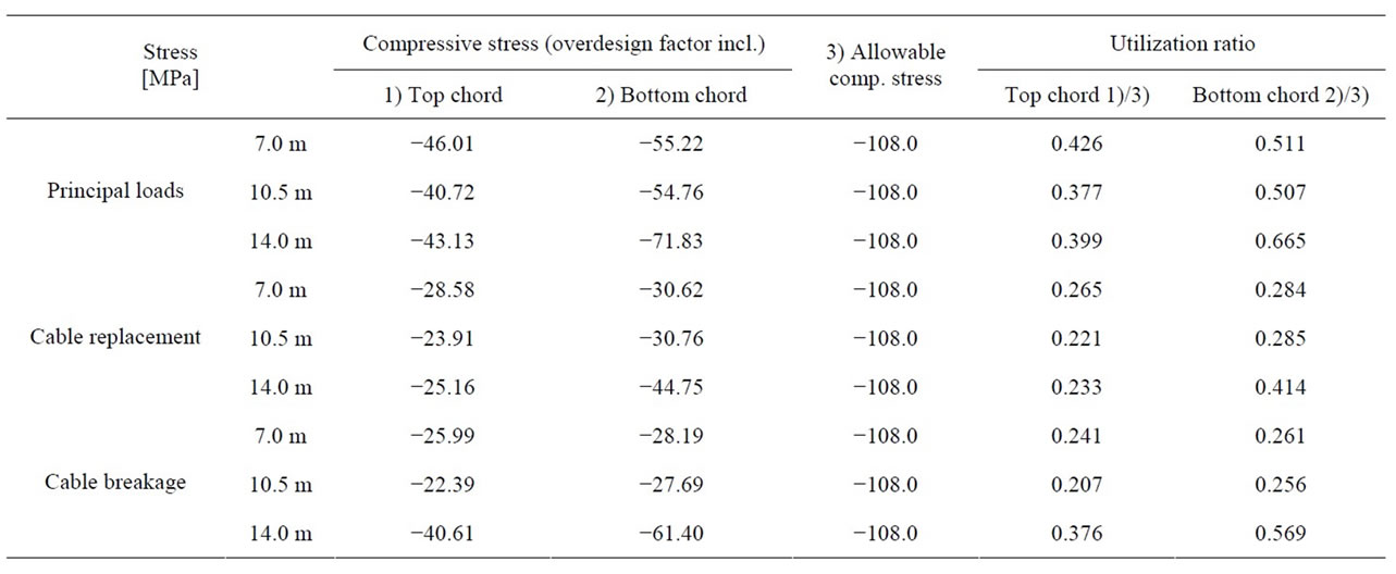
Table 1. Compressive stress by allowable stress combination (pylon).

Table 2. Tensile stress by allowable stress combination (center of main span).
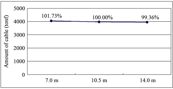
Figure 4. Amount of cables per cable spacing.
in the cross-section exceeding the allowable tensile stress per cable spacing of the hybrid cable-stayed bridge. These amounts are computed assuming that the tendons installed at mid-span will resist axially by being arranged at the centroid of the cross-section. For the cable spacing of 14.0 m, the prestress stress to be introduced in the up-

Figure 5. Amount of tendons required per cable spacing.
per girder reaches a high value of 53.52 MPa, which represents a surplus in steel wires of 36% compared to the 10.5 m cable spacing. Following, the additional arrangement of steel wires all along the stiffening girder to prepare for extreme events will cause not only the increase of the construction cost but also the extension of the construction period.
Figure 6 compares the construction cost according to the cable spacing for the amount of tendons shown in Figure 5 as the sum of construction costs of the upper girder, steel wires, cables (including the anchorages) and pylons. The results indicate that the cable spacing of 10.5 m is the most cost efficient but with a benefit below 1%.