Electronically Controllable Fully-Uncoupled Explicit Current-Mode Quadrature Oscillator Using VDTAs and Grounded Capacitors ()
1. Introduction
Among various kinds of oscillators, the quadrature oscillators (QO) are widely used because they can provide two sinusoids with π/2 phase difference, for example, in telecommunication systems, for quadrature mixtures and single-sideband generators or for measurement purposes in vector generators or selective voltmeters [1,2]. Therefore the QO play an important role in many communication systems, instrumentation systems and signal processing see [3-11]. Recently, a CMOS realization of VDTA and its applications as 1) RF filter and 2) double tuned amplifier have been presented in [12]. In [13], an electronically controllable explicit current-output sinusoidal oscillator has been reported. Another application as a single input five output voltage-mode universal filter using VDTAs has been presented in [14]. The purpose of this communication is to introduce a new electronically controllable fully uncoupled explicit current-mode quadrature oscillator using two VDTAs and two grounded capacitors. The proposed configuration provides the advantageous features of: 1) completely and electronically independent control of condition of oscillation (CO) and frequency of oscillation (FO); 2) explicit current-mode quadrature oscillations; and 3) low active and passive sensitivities. The workability of proposed configuration has been verified using SPICE simulation with TSMC CMOS 0.18 μm process parameters.
2. The Proposed Configurations
The symbolic notation of the VDTA is shown in Figure 1, where VP and VN are input terminals and Z, X+ and X− are output terminals. All terminals of VDTA exhibit high impedance values [12]. The VDTA can be described by the following set of equations:
 (1)
(1)
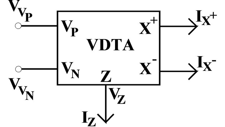
Figure 1. The symbolic notation of VDTA.
The proposed configuration is shown in Figure 2.
Circuit analysis of Figure 2 gives the characteristic equation (CE) as:
 (2)
(2)
From Equation (2), the CO and FO can be expressed as CO:
 (3)
(3)
and FO:
 (4)
(4)
Therefore, it is seen from Equations (3) and (4) that the CO and FO are completely uncoupled and electronically tunable as  i = 1 − 4 are controlled by bias currents.
The current transfer functions obtained from Figure 2 are given by:
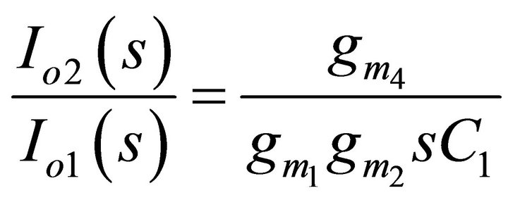 (5)
(5)
For sinusoidal steady state, Equations (5) becomes
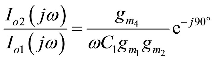 (6)
(6)
Thus, the phase difference f between (Io2 and Io1) is −90˚. Hence, the currents (Io2 and Io1) are in the quadrature form.
3. Parasitic Effects and Sensitivity Analysis
By considering the various VDTA non-ideal parameters like the finite P-terminal parasitic impedance consisting of a resistance RP in parallel with capacitance CP, the finite N-terminal parasitic impedance consisting of a resistance RN in parallel with capacitance CN, the finite X-terminal parasitic impedance consisting of a resistance RX in parallel with capacitance CX and the parasitic impedance at the Z-terminal consisting of a resistance RZ in parallel with capacitance CZ then the expression of CO and FO including the influence of parasitic are given by:
CO:
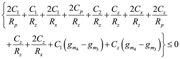 (7)
(7)
FO:
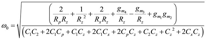 (8)
(8)
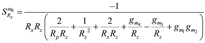
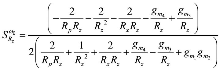
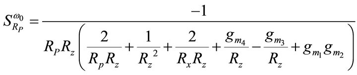
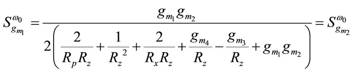
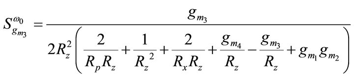
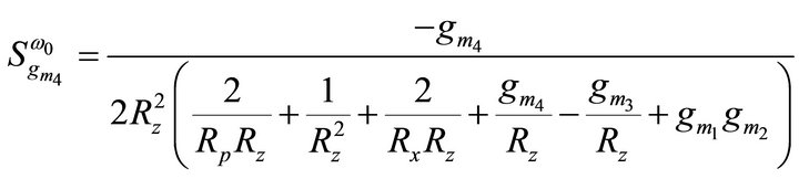
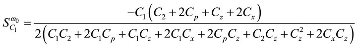
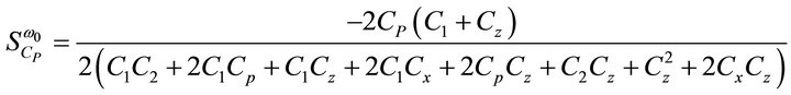
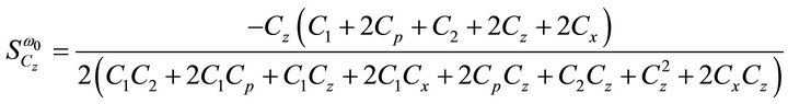
then the active and passive sensitivities of ω0 can be found as:
 ,
,  ,
,
 ,
,  ,
,
 ,
,  ,
,
 ,
,
 ,
,
 ,
,
 ,
,
 (9)
(9)
For C1 = C2 = 0.5 nF, Rp = Rz = ∞, Cp = Cx = Cz = 0.15 pF,  =
=  =
=  = 1.5913 mA/V and
  = 1.7916 mA/V, the sensitivities are found to be 0, 0, 0, 0.5, 0, 0, −0.899, −0.499, −2.9e−4, −2.9e−4, −1.64e−3 for Equation (9). Thus, all the active and passive sensitivities of ω0 with respect to each active and passive elements are low.
4. Simulation Results
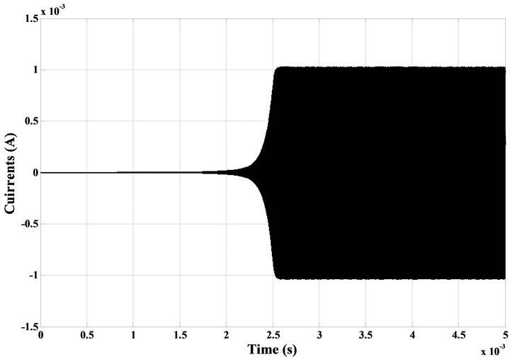
To verify the theoretical analysis, the proposed ECMSO was simulated using CMOS VDTA from [12]. Power supply voltages were taken as VDD = −VSS = 0.9 V and IB1 = IB2 = IB3 = IB4 = 2 mA (for VDTA1) and IB1 = IB2 = 2 mA, IB3 = IB4 = 3.687 mA (for VDTA2) biasing currents are used. The transistor aspect ratios are same as in [12]. The passive elements of the configuration were selected as C1 = C2 = 0.5 nF. The transconductances of VDTA were controlled by bias currents. PSPICE generated output waveforms indicating transient and steady state responses are shown in Figures 3(a) and (b) respectively. These results, thus, confirm the validity of the proposed configuration. The total harmonic distortion (THD) of the proposed oscillator is found to be 3.00% (Figure 4). From Figure 5 it is clear that the two currents are in quadrature.
Figure 5 shows that the two currents are in quadrature and the measured value of phase shift between two waveforms is = −89.98˚.
5. Concluding Remarks
In this paper, an explicit current-mode quadrature oscillator using VDTAs has been presented. The presented circuit employs two VDTAs and two grounded capaci-
 (a)
(a)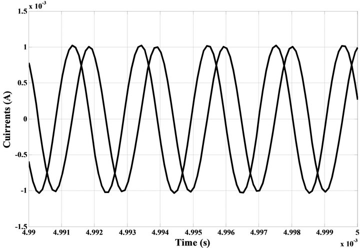 (b)
(b)
Figure 3. (a) Transient response waveform; (b) Steady state response of the quadrature outputs.
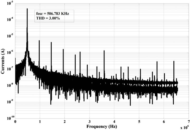
Figure 4. Simulation result of the output spectrum.
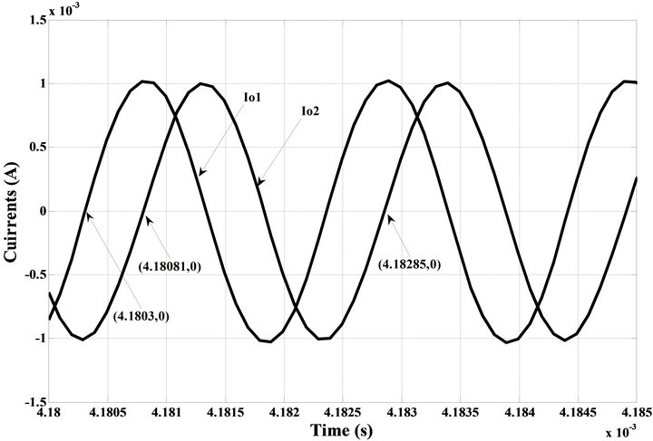
Figure 5. Steady state response of the quadrature outputs of Io2 and Io1.
tors. The CO and FO of the proposed quadrature oscillator has the advantage of fully and electronically independent controllability. The proposed explict currentmode quadrature oscillator also provides low active and passive sensitivities. The workability of proposed configuration has been verified using SPICE simulation.
NOTES