Introduction of Compressive Residual Stress by Means of Cavitation Peening into a Titanium Alloy Rod Used for Spinal Implants ()
1. Introduction
Titanium alloy Ti-6Al-4V is widely used for spinal implant rods because of its high biocompatibility, high strength, high resistance to corrosion and light weight. However, the reliability of such metal as a biological compatible material needs to be further enhanced, particularly in terms of its resistance to fretting fatigue, fretting wear and mechanical fatigue, since it is hard to replace the implant rod when it is broken. For the spinal implant, fretting fatigue and fretting wear caused between the rod and the holding fixture are a known problem. One effective way to suppress such failure mechanisms and tribology characteristics is the introduction of compressive residual stress into the surface layer. For this reason, there has been an attempt to enhance the reliability of the titanium alloy used for the spinal implant rod by use of peening techniques, which are known to introduce compressive residual stress into the surface layer [1]. The compressive residual stress enhances the resistance to fatigue [2-4], stress corrosion cracking [5] and hydrogen embrittlement [6-8]. Several practical peening techniques have been developed such as shot peening, which utilizes impact caused by collision between solid bodies, laser peening, which utilizes the impact caused by an ablative interaction and cavitation peening, which utilizes the impacts caused by the collapse of cavitation bubbles. These peening techniques have been applied for the treatment of mechanical components, e.g., automotive components and large structural components, e.g., the shroud installed in a nuclear power plant.
Several studies have been conducted on the enhancement of Ti-6Al-4V to mitigate the fretting fatigue and fretting wear by employing various peening methods [9-12]. However, these studies considered plate shaped specimens, essentially simulating the shape of blades and disks installed in gas turbine engines (e.g., reference [13]). When peening is applied for a small rod such as the spinal implant rod in question, the treatment is not simple due to its small size and curved form. In this study, in order to introduce compressive residual stress into a titanium alloy Ti-6Al-4V small rod used for the spinal implants, a method of cavitation peening employing a controlledand enhanced-cavitating jet in water was chosen.
A cavitating jet has been successfully applied as a method of metallic material peening. The resulting socalled “cavitation peening” utilizes the impact energy arising from the collapse of cavitation bubbles. To apply the cavitating jet to a small rod, the ambient pressure needs to be controlled in order to generate a suitable jet shape. When applied to a plate-like surface, cavitation bubbles are still growing after the jet impinges on the surface and then they collapse. However, in a case of small rod shape, the cavitation bubble needs to be sufficiently grown in the jet since it cannot grow well on the rod surface. The collapse area of the cavitation bubbles can be controlled by the ambient pressure [14]. At low ambient pressure, e.g., atmosphere pressure, cavitation bubbles collapse within a large area and the number of cavitation bubbles collapsing per unit area is low. In contrary, at high ambient pressure, the cavitation bubbles collapse within a small area, and the number of cavitation bubble collapsing per unit area is high [15]. To treat effectively the surface of a metallic rod which is only several millimeters in diameter, the ambient pressure needs to be raised much higher than atmosphere pressure, in order to induce cavitation bubble collapse within a small area.
In this study cavitation peening has been employed in order to introduce compressive residual stress into a spinal implant rod manufactured from titanium alloy Ti- 6Al-4V. The ambient pressure was kept much higher than atmosphere pressure at 0.84 MPa, so as to apply the method successfully to the small rod which has a diameter of only 5.5 mm. After treatment using a variable processing time, the depth profiles of residual stress for the specimens were evaluated by X-ray diffraction using electropolishing for material removal. The results provide the first demonstration that cavitation peening can introduce additional compressive residual stress into a deeper region of the Ti-6Al-4V spinal implant rod at a depth beyond that produced by glass shot peening.
2. Experimental Apparatus and Procedures
The material under test was manufactured from medical grade titanium alloy rod Ti-6Al-4V Extra Low Interstitial (ELI) produced by X-spine Systems Inc., a spinal implant manufacturing company. The rod has a diameter of 5.5 mm and a length of 150 mm. The rod was already processed by glass shot peening, which introduces high compressive residual stress into a thin surface region. This rod has been employed for spinal implants and is a successful commercialized product. In this study, the rod was trisected, so the specimens used for treatment by cavitation peening had a length of 50 mm.
The schematic diagram of the cavitating jet apparatus and the nozzle shape used for the experiments are shown in Figures 1 and 2, respectively. The high-speed water jet was pressurized by a plunger pump that has a maximum pressure of 35 MPa, and was injected into the test section through the nozzle. The injection pressure, p1, was controlled by the velocity of the inverter motor connected to the plunger pump. The test section’s ambient pressure, p2, was controlled by the downstream valve.
The cavitating jet significantly changes its shape and aggressive strength as a function of the cavitation number, σ [16]. Generally, the cavitation number is defined by a ratio of the hydrodynamic pressure and static pressure at the cavitating flow [17]. In the case of nozzle and orifice flows, the cavitation number of a cavitating jet can be defined as Equation (1), as a function of the injection pressure p1, ambient pressure p2, and the vapor pressure of the test water, pv.
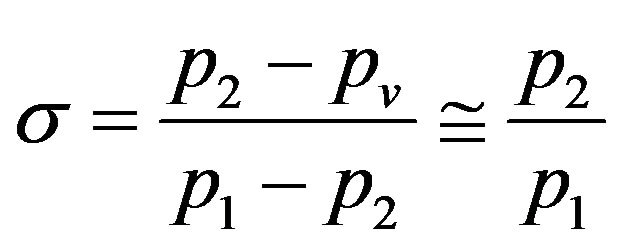 (1)
(1)
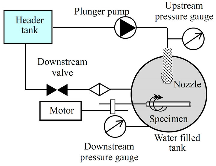
Figure 1. Apparatus for cavitation peening employing a cavitating jet in water.
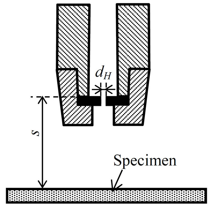
Figure 2. Nozzle for cavitating jet in water.
the simplification of the above relationship occurs since .
.
In this study, the pressure of the high-speed water jet, p1 and the ambient pressure, p2, were set to 30 MPa and 0.84 MPa, respectively, in order to keep the cavitation number σ equal to 0.028. The nozzle diameter, dH, and the standoff distance, s, which is defined as the distance between the nozzle and specimen were 2 mm and 55 mm, respectively. The specimen was rotated in order to be treated uniformly and the processing time per unit length, tp, was varied by changing the rotation speed from tp = 0 (not-treated) to 0.5, 1, 2, 5 and 10 s/mm. The “untreated” specimen represents the initial specimen processed by glass shot peening, whilst the other specimens were additionally treated by cavitation peening.
The surface residual stress in the longitudinal direction of the Ti-6Al-4V rod, σR, was evaluated using a sin2ψ X-ray diffraction method (PROTO LXRD), employing an X-ray tube with a Cu target operated at 30 kV and 30 mA. X-rays from the Kα peak were chosen. The diffracted X-ray was detected by two position sensitive proportional counters (PSPCs). An aperture having a width of 0.2 mm and length of 3 mm was used in order to apply this technique to the small rod diameter. The diffractive plane was the (2 1 3) plane of Ti and the diffraction angle without strain 2θ was 142 degrees. The incident angle, β, defined as the angle between the normal to a surface and the irradiation axis for X-ray was varied as β = 0, ±1.59, ±6.04, ±12.22, ±23.00. The total exposure time at each β was 250 seconds. So as to detect diffracted X-rays effectively from several grains the β angle was oscillated over a width of 5 degrees.
The depth profiles of residual stress for all the specimens were evaluated through a combination of X-ray diffraction measurements and layer removal by electropolishing. In order to remove the rod surface uniformly, an electrode was shaped into a cylindrical configuration and the specimen was placed at the center of the electrode. The solution used for electropolishing was a mixture of 87.5 volume percent methanol and 12.5 volume percent sulfuric acid. After layer removal, the residual stress can be corrected to take account of the effect of stress release due to the layer removal on the depth profile. In this study, the stress correction was done based on a SAE standard method [18], which describes the correction method to be used for a case of the rod shaped specimen.
In the residual stress measurements, the full width at half maximum value was also evaluated. The presence of micro-strain has the possibility of being an origin for crack initiation. The full width at half maximum value of the diffraction profile has a close relationship with the micro-strain caused by the adjacent grains and the random strain in the grains. The micro-strain can therefore be evaluated before and after cavitation peening by measuring the full width at half maximum value of the diffraction profile.
In order to verify the surface situation after treatment by cavitation peening, surface roughness measurements in the longitudinal direction were conducted by means of a stylus method and the surface observed using a digital microscope with magnification of ×100. In the surface roughness measurements, the results for surface roughness were obtained as the average of five sets of experimental data.
3. Results and Discussion
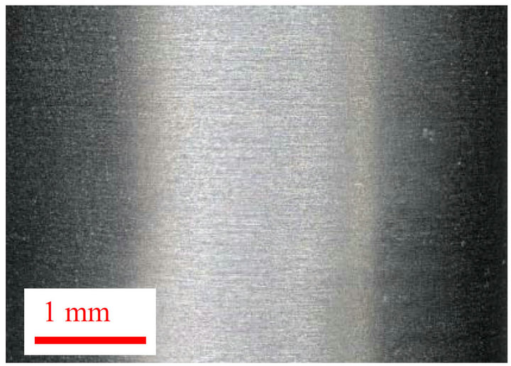
Figure 3 shows images of an untreated rod (tp = 0 s/m; previously processed by glass shot peening) and a cavitation peening treated specimen (tp = 10 s/m). On the surface of the tp = 10 s/m specimen several large plastic deformation pits can be observed, induced by impacts attributed to the collapse of cavitation bubbles. In contrast, on the surface of the untreated (tp = 0 s/m) specimen large pits cannot be observed. It can be suggested from these images that cavitation peening could introduce compressive residual stress deeper into the surface than those previously introduced by glass shot peening, since
 (a)
(a) (b)
(b)
Figure 3. Images of the treated surface. (a) Untreated surface (previously processed by glass shot peening); (b) Treated surface by cavitation peening.
the impacts generated by the collapse of cavitation bubbles appear are more aggressive, inducing additional plastic deformation pits onto the plastic deformed surface formed after glass shot peening. Figure 4 plots the arithmetic averaged surface roughness, Ra, as a function of processing time per unit length of cavitation peening, tp. In Figure 4, the surface of the specimen for tp = 0 s/m, due to glass shot peening has an initial value of Ra = 1.05 m and increases with increasing processing time due to the generation of large plastic deformation pits produced by cavitation peening as shown in Figure 3(b).
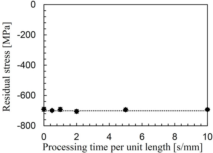
Figure 5(a) plots the residual stress in longitudinal direction, σR, at the surface as a function of the processing time per unit length, tp, and Figure 5(b) plots the depth profile of the residual stress evaluated by X-ray diffraction followed by surface removal by electropolishing. The negative value on the plots represents compressive stress. In Figure 5(a), the untreated specimen (tp = 0 s/m) has a high compressive residual stress of σR = −691 MPa at the near surface due to the initial glass shot peening process. The maximum compressive residual stress keeps constant around σR = −700 MPa even though the processing time of the cavitation peening increases. This is because there is a saturated high level of plastic strain at the near surface due to the glass shot peening process. Further plastic strain was not introduced at the near surface by the impacts caused by cavitation bubble collapse. However, in Figure 5(b) it can be seen that the depth profiles are changed remarkably by cavitation peening and that the compressive residual stress profile extends into a deeper region with increasing processing time. Whereas compressive residual stress falls to zero at a depth of 44 μm for the specimen with tp = 0 s/mm, the compressive residual stress of the specimens with tp = 0.5, 1, 2, 5, 10 s/mm are σR = −88, −200, −264 and −370 MPa respectively at this depth. The compressive residual stress of all the specimens has a maximum value of about 750 MPa at around d = 10 μm due to Hertzian contact during the glass shot peening process. The depth profiles
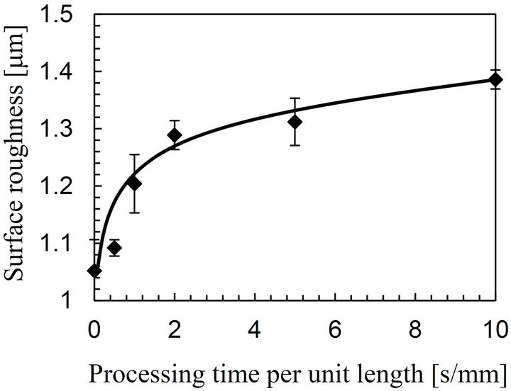
Figure 4. Varying surface roughness with processing time of cavitation peening.
 (a)
(a) (b)
(b)
Figure 5. Introduction of compressive residual stress into Ti-6Al-4V rod surface by cavitation peening. (a) Residual stress at near surface; (b) Depth profile of the compressive residual stress.
for each specimen change for depths beyond the maximum value of the compressive residual stress. At tp = 0 s/mm, the compressive residual stress rapidly decreases with increasing depth, whereas the stress profiles of the treated specimens decrease much more slowly.
The depth of the introduced compressive residual stress, dc, obtained from the depth profile is plotted against the cavitation peening processing time, tp, in Figure 6. The depth of the compressive residual stress increases rapidly from the initial value of dc = 44 μm at tp = 0 s/mm until tp = 2 s/mm, after which the increase is more incremental. The maximum value of dc = 230 μm we have measured occurs for tp = 10 s/mm, but no sign of saturation of the depth is observed.
The reason why the depth of the compressive residual stress continuously increases with increasing processing time can be explained by considering the relationship between the aggressive strength of the cavitation impact and its frequency. For the cavitating jet, the frequency of impacts with a high aggressive strength is relatively low compared to the frequency of smaller impacts. The distribution of the frequency versus the aggressive strength has a tendency to follow a Poisson distribution as reported in [19]. As the near surface, the compressive residual stress becomes saturated due to the high fre-
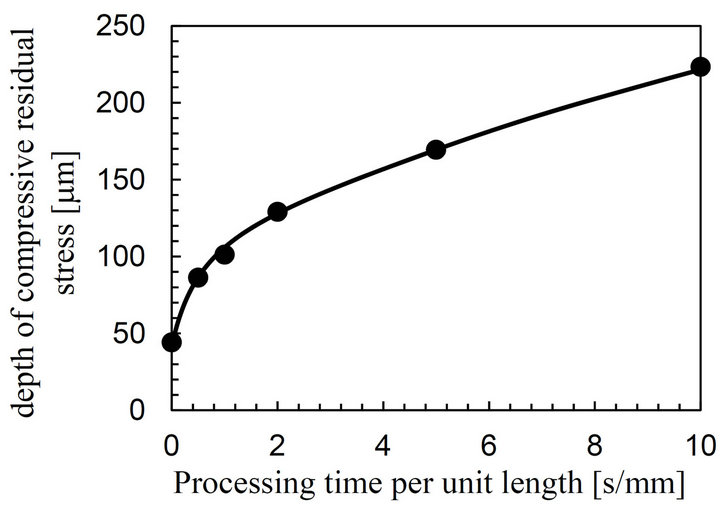
Figure 6. Depth of introduced compressive residual stress varying with processing time.
quency of small impacts. However the depth of the compressive strain increases when the surface is subjected to large impacts with a high aggressive strength, with the effect increasing with increasing processing time. A comparison of Figure 6 with Figure 4 shows that they have a very similar tendency. It is quite likely that the generation of large plastic deformation pits due to cavitation bubble collapse at the rod surface is related to the introduction of compressive residual stress into deeper regions of the material.
Figure 7 plots the full width at half maximum value, FWHM, at the near surface obtained from the residual stress measurements, taken at β = 0 degree for each processing time per unit length, tp. In general, the micro-strain of materials significantly increases due to mechanical processing processes such as surface finishing and peening, and decreases when annealed. As shown in Figure 7, the FWHM suddenly decreases at tp = 1 s/mm and then saturates. The high value of FWHM at tp = 0 s/mm (FWHM = 3.764 degree) is due to the effect of glass shot peening. Overall, the full width at half maximum value decreases to FWHM = 2.591 degree at tp = 10 s/mm by an amount of almost 32%. In the past literature, it has been shown that a cavitating jet can release micro-strain whilst also introducing compressive residual stresses in tool alloy steel [20]. It is likely that the ultrasound produced by cavitation bubble collapse moves dislocations which may be a source of the micro-strain [21]. Since the micro-strain has the possibility of being an origin for crack initiation, the observed decrease in the full width at half maximum value can be seen as a favorable effect for improved reliability. It can be concluded that cavitation peening can release the micro-strain previously introduced by glass shot peening of the titanium alloy rod, whilst introducing compressive residual stresses deeper into the surface than those caused by the initial glass shot peening treatment.
4. Conclusions
It has been demonstrated the introduction of compre-
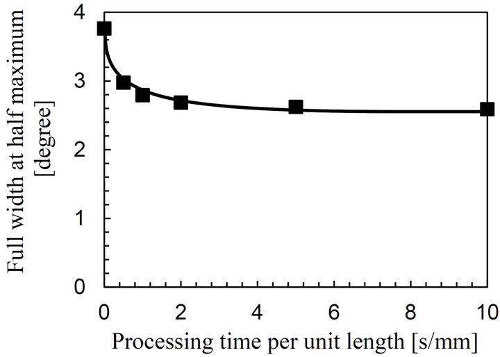
Figure 7. Decrease in full width at half maximum value by cavitation peening.
ssive residual stress by cavitation peening into a titanium alloy Ti-6Al-4V rod used for spinal implants which has been previously processed by glass shot peening. The cavitation peening was achieved using a precisely controlled cavitating jet in water. The resulting depth profiles of the compressive residual stress were evaluated by X-ray diffraction. The conclusions obtained in the present study are summarized as follows.
1) Cavitation peening introduces compressive residual stress deeper into the rod. The depth of introduced compressive residual stress continuously increases up to 230 μm at a processing time per unit length of 10 s/mm. This occurs despite the fact that the strain at the near surface has been saturated due to the initial glass shot peening process.
2) The full width at half maximum value, which has close relationship to the magnitude of the micro-strain, decreases by almost 32% following the cavitation peening process. It is suggested that cavitation peening might release the micro-strain initially introduced by the glass shot peening process.
NOTES