Modern Mechanical Engineering
Vol.2 No.3(2012), Article ID:22204,8 pages DOI:10.4236/mme.2012.23013
A Theoretical Investigation of Efficiency Enhancement in Thermal Power Plants
Department of Industrial Production Engineering, GITAM Institute of Technology, Gitam University, Visakhapatnam, India
Email: venkat.seshendra@gmail.com, venkat_seshendra@yahoo.co.in
Received May 16, 2012; revised June 18, 2012; accepted June 27, 2012
Keywords: Thermal Power Plant; Power Enhancement; Flue Gas Desulphurization; Direct Method; Indirect Method; Flue Gas Loss
ABSTRACT
The need to operate a boiler efficiently in today’s environment is at the top of many plant owners and operators lists. Unfortunately, operating a boiler efficiently and meeting local emission regulations do not always go hand in hand. However, advances in boiler system design and technology have made this a much more achievable task. The potential for energy improvements and cost savings is substantial when considered that most boilers operating today are performing at efficiencies that are less than 70 percent. The performance calculation and rectification measures are essential for performance evaluation and efficiency enhancement. Since the efficiency decreases from time to time it is required to find out the losses occurring in boiler using proper methodology. The environmental issues and economy are the secondary factors to be considered after finding the losses. Due to increase in fuel price and demand in more energy requirement in everyday life, proper utilization of materials and resources are necessary. This present deals with the aim of estimating the heat losses occurring in thermal power plant boilers and hence finding suitable ways for reducing it, hence allowing plants to achieve more performance, sustainability and cost-effective maintenance operation of a steam system.
1. Introduction
The Brayton cycle was first proposed in 1870 by George Brayton for use in the reciprocating oil-burning engine. Now a day, it is used for gas turbines only where both the compression and expansion processes take place in rotating machinery. Gas turbines usually operate on an open cycle. N. Arai et al. [1] in their work specified about the maximum work transfer, which can be obtained from that form of energy. The availability of heat transfer Q from the control surface at temperature T is determined from maximum rate of conversion of thermal energy to work Wmax. Bejan [2] draw outlines the fundamentals of the methods of energy analysis and entropy generation minimization (or thermodynamic optimization-the minimization of exergy destruction). The paper begins with a review of the concept of irreversibility, entropy generation, or exergy destruction. Examples illustrate the accounting for energy flows and accumulation in closed systems, open systems, heat transfer processes, and power and refrigeration plants. George and Park [3] discusses how to estimate the avoidable and unavoidable energy destruction and investment costs associated with compressors, turbines, heat exchangers and combustion chambers. This general procedure, although based on many subjective decisions, facilitates and improves applications of exergo-economics. Kotas [4] explained in this work the concept of exergy used to define criteria of performance of thermal plant. Ganapathy et al. [5] studied with an exergy analysis performed on an operating 50 MW thermal power unit. The distribution of the exergy losses in several plant components during the real time plant running conditions has been assessed to locate the process irreversibility. The comparison between the energy losses and the exergy losses of the individual components of the plant shows that the maximum energy losses of 39% occur in the condenser, whereas the maximum exergy losses of 42.73% occur in the combustor. Kamate and Gangavati [6] studied exergy analysis of a heat-matched bagasse-based cogeneration plant of a typical 2500 tcd sugar factory, using backpressure and extraction condensing steam turbine is presented. In the analysis, exergy methods in addition to the more conventional energy analyses are employed to evaluate overall and component efficiencies and to identify and assess the thermodynamic losses. Boiler is the least efficient component and turbine is the most efficient component of the plant. The results show that, at optimal steam inlet conditions of 61 bar and 475˚C, the backpressure steam turbine cogeneration plant perform with energy and exergy efficiency of 0.863 and 0.307 and condensing steam turbine plant perform with energy and exergy efficiency of 0.682 and 0.260. Datta et al. [7] was presented work on exergy analysis of a coal-based thermal power plant is done using the design data from a 210 MW thermal power plant under operation in India. The exergy efficiency is calculated using the operating data from the plant at different conditions, viz. at different loads, different condenser pressures, with and without regenerative heaters and with different settings of the turbine governing. The load variation is studied with the data at 100, 75, 60 and 40% of full load. Effects of two different condenser pressures, i.e. 76 and 89 mmHg (abs.), are studied. It is observed that the major source of irreversibility in the power cycle is the boiler, which contributes to exergy destruction of the order of 60%. Part load operation increases the irreversibilities in the cycle and the effect is more pronounced with the reduction of the load. Increase in the condenser back pressure decreases the exergy efficiency. Successive withdrawal of the high pressure heaters shows a gradual increment in the exergy efficiency for the control volume excluding the boiler. Aljundi [8] was presented in this study, the energy analysis of Al-Hussein power plant in Jordan is presented. The primary objectives of this paper are to analyze the system components separately and to identify and quantify the sites having largest energy losses. In addition, the effect of varying the reference environment state on this analysis will also be presented. Energy losses mainly occurred in the condenser where 134 MW is lost to the environment while only 13 MW was lost from the boiler system. For a moderate change in the reference environment state temperature, no drastic change was noticed in the performance of major components.
Steel industry is a power intensive industry and requires uninterrupted power supply to critical loads. This requires a dependable and reliable captive power source which can cater to all important loads of the plant all the time for safe and smooth operation of the steel plant. Thermal Power Plant (TPP) serves the above purpose, TPP has a nameplate generating potential of 286.5 MW including auxiliary limits to cater to the plant load requirements and to export surplus power as and when required. Thermal Power Plant has 5 Boilers each of 330 T/hr Steam capacity at 101 ATA and 540˚C. The Boilers are of BHEL make, capable of firing combination of fuels namely, Coal, Coke Oven Gas, Blast Furnace Gas and Oil. Crushed coal is conveyed from Raw Material Handling Plant to TPP through conveyors. The Coal is pulverized in Bowl Mills and fired in the furnace. Normally 4 Boilers are kept in full load operation to produce 247.5 MW of power, supply steam to 2 Turbo Blowers and process needs. Boiler’s outlet flue gas is passed through Electro Static Precipitators to control air pollution. The fly ash and Bottom Ash generated are pumped in slurry from to Ash Pond through on ground pipe lines. The clarified water is re-circulated back to ash system. The hot circulating gas is passed through Waste Heat Boilers in which steam is produced at 40 KSCA pressure and 440˚C temperature. There are three Coke Dry Cooling Plant four Waste Heat Boilers. Boiler is of 25 T/hr Capacity. These are once through, forced circulation Boilers, Deaerators and Boiler Feed Pumps, serving all the 3 plants, are located at CDCP-1.
2. Energy Performance Assessment of Boilers
In TPP, 5 boilers are installed with a capacity of 330 ton/ hr each with 101 ATA and 12 auxiliary waste heat recovery boilers installed capacity 25 ton/hr each 40 ATA, to supply steam to turbo generators for power generation and 13 ATA, 7 ATA steam for different processes throughout the plant. Performance of the boiler, like efficiency and evaporation ratio reduces with time, due to poor combustion, heat transfer fouling and poor operation and maintenance. Deterioration of fuel quality and water quality also leads to poor performance of boiler. Efficiency testing helps us to find out how far the boiler efficiency drifts away from the best efficiency. Any observed abnormal deviations could therefore be investigated to pinpoint the problem area for necessary corrective action. Hence it is necessary to find out the current level of efficiency for performance evaluation, which is a pre requisite for energy conservation action in industry. The process flow chart of thermal power plant is shown in the Figure 1.
The Purpose of the Performance Test is:
1) To find out the efficiency of the boiler;
2) To find out the Evaporation ratio.

Figure 1. Process flow chart of TPP.
The purpose of the performance test is to determine actual performance and efficiency of the boiler and compare it with design values or norms. It is an indicator for tracking day-to-day and season-to-season variations in boiler efficiency and energy efficiency improvements. The procedure describes routine test for both oil fired and solid fuel fired boilers using coal, agro residues etc. Only those observations and measurements need to be made which can be readily applied and is necessary to attain the purpose of the test.
2.1. The Direct Method Testing
This is also known as “input-output method” due to the fact that it needs only the useful output (steam) and the heat input (i.e. fuel) for evaluating the efficiency. This boiler efficiency can be evaluated using the formula given above and the heat flow in the boiler using the method of direct testing is shown in the Figure 2.
2.2. The Indirect Method Testing
The disadvantages of the direct method can be overcome by this method, which calculates the various heat losses associated with boiler. The various losses that had occurred in the boiler are shown in the Figure 3. The efficiency can be arrived at, by subtracting the heat loss fractions from 100.An important advantage of this method is that the errors in measurement do not make significant change in efficiency.
Thus if boiler efficiency is 90%, an error of 1% in direct method will result in significant change in efficiency. i.e. 90 ± 0.9 = 89.1 to 90.9. In indirect method, 1% error in measurement of losses will result in Efficiency = 100 - (10 ± 0.1) = 90 ± 0.1 = 89.9 to 90.1. In order to calculate the boiler efficiency by indirect method, all the losses that occur in the boiler must be established. These losses
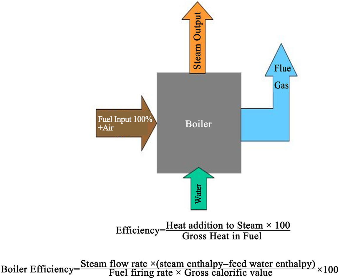
Figure 2. Heat flow in boiler.
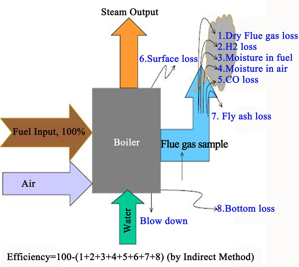
Figure 3. Losses occurring in the boiler.
are conveniently related to the amount of fuel burnt. Theoretical (stoichiometric) air fuel ratio and excess air supplied are to be determined first for computing the boiler losses.
3. Experimentation
Efficiency of boilers in steel plant is calculated by Indirect Method and a sample calculation is shown below. The Heat balance sheet is also prepared. The calculations are shown along with the heat balance sheet. The parameters are obtained from the shift operator log book from Main Control Room, TPP.
Parameters for Boiler Efficiency Calculation
Fuel firing rate = 2560 tons/hr;
Steam generation rate = 330 tons/hr;
Steam pressure = 101 ATA;
Steam temperature = 533˚C;
Feed water temperature = 196˚C;
% CO2 in Flue gas = 12;
% CO in flue gas = 0.50;
Average flue gas temperature = 190˚C;
Ambient temperature = 36˚C Humidity in ambient air = 0.0204 kg/kg dry air;
Surface temperature of boiler = 165˚C;
Wind velocity around the boiler= 3.5 m/s;
Total surface area of boiler = 7397 m2;
GCV of Bottom ash = 600 kCal/kg;
GCV of fly ash = 452.5 kCal/kg;
Ratio of bottom ash to fly ash = 80:20.
Fuel Analysis (in %)
Ash content in fuel = 40.19;
Moisture in coal = 12.5;
Carbon content = 44.93;
Hydrogen content = 2.64;
Nitrogen content = 1.56;
Oxygen content = 14;
GCV of Coal = 2850 kcal/kg.
4. Results and Discussion
4.1. Heat Recovery and Performance Enhancement
Based upon the efficiency calculations, we have found that lot of heat energy is wasted from flue gas loss and loss due to moisture content in fuel. Moreover due to moisture in fuel, lot of energy is wasted as unburned fuel or formation of bottom ash. So to enhance the performance of boilers, we have to extract sensible heat from flue gas and use it for various purposes keeping in mind that decreasing the flue gas temperature will increase the sulphuric acid content and decrease the moisture in fuel or using quality fuel that has low ash content. This in fact involves various factors such as large investment, economy, environmental factors, plant layout, etc. So to increase the efficiency of the boilers, we should find the best practices for decreasing the flue gas loss and reduce the moisture content in fuel.
4.2. Heat Recovery from Flue Gas
The temperature of the flue gas leaving the boiler is commonly reduced in an air pre-heater (APH) when the sensible heat in the flue gas leaving the economizer is used to preheat combustion air. Preheating of combustion air has a significant positive effect on boiler efficiency. Sulfuric acid in the flue gas is formed in gas-phase reactions of SO3 and H2O upstream of the APH. The SO3 is formed from SO2 by homogeneous and heterogeneous reactions in the furnace and convection pass of the boiler. The presence of SO3 in the flue gas increases the dew point of the flue gas. The acid dew point temperature is presented in Figure 4 as a function of the SO3 and H2O concentration in the flue gas. Sulfuric acid condenses as temperature is decreased bellow the dew point temperature. The condensed sulfuric acid (acid and water mixture sulfuric acid is hydroscopic) is corrosive to the inexpensive materials used in construction of the APH heat transfer surfaces and downstream ductwork.
Besides acid deposition, the other impediment to recovering heat from the flue gas by additional cooling in the APH is the ESP performance. The ash samples were taken from the electrostatic precipitator when operating in descending temperature mode at 7.2% moisture content. As presented in Figure 5, resistivity of fly ash decreases as the flue gas temperature is reduced below

Figure 4. Acid dew point temperature as a function of the SO3 and H2O concentration.
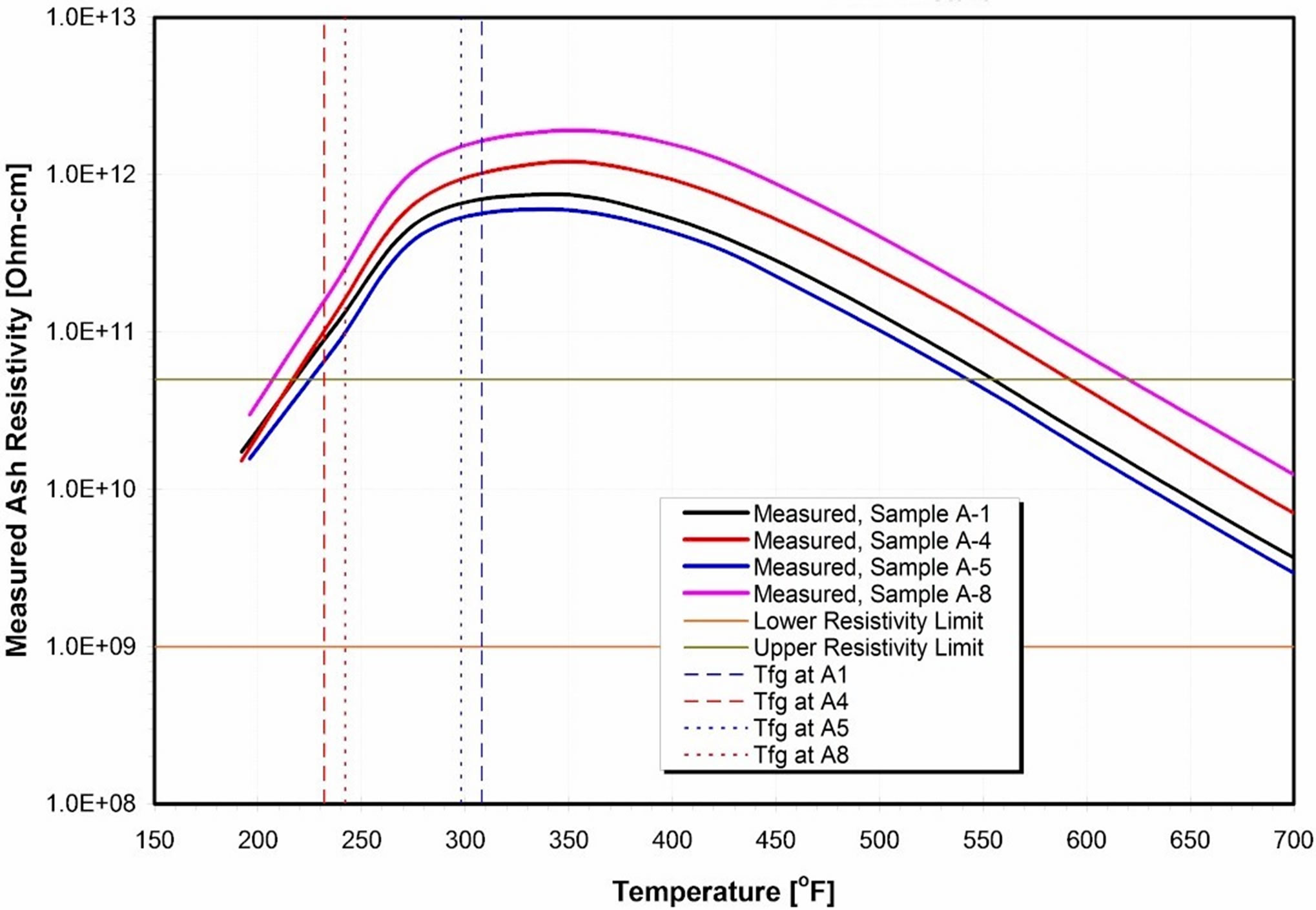
Figure 5. Ash resistivity versus flue gas temperature for a high-resistivity ash.
300F. However, in case of the high-resistivity ash, the temperature reduction would not be a problem, for the low-resistivity ash low flue gas temperatures will have a significant negative effect on the ESP performance. Un-reacted ammonia combines with SO3 in the flue gas stream and SO3 produced on the SCR catalysts to form ammonium bisulfate (ABS). The ABS forms in a temperature range between the APH flue gas inlet and outlet temperatures. The deposits are sticky and corrosive to steels commonly employed in the APHs. Upon exiting the ESP, it is common to cool the flue gas by evaporative cooling to a temperature close to the adiabatic saturation temperature by spraying water into the flue gas stream within a wet flue gas desulfurization (FGD) system.
According to an FGD manufacturer, the optimal flue gas temperature for a desulfurization process is approximately 149F (65˚C). Cooling of the flue gas to the saturation temperature occurs in a spray area, and the flue gas leaves the FGD reactor at a temperature close to the saturation temperature. Most of the moisture can be removed from the flue gas by cooling it to a very low temperature. The chilled ammonia concept, developed by Alstom Power, employs cooling of the flue gas to a very low temperature using chillers.
At the current state of technology development, such low-temperature cooling of the flue gas is expensive due to high power requirements for the chillers. Condensation of the flue gas moisture liberates latent heat. The amount of latent heat released is a function of the flue gas temperature and coal type. The amount of released latent heat increases as TM content of the coal increases and temperature of the flue gas decreases. The latent heat can be recovered in condensing heat exchangers (CXEs), but due to the low temperature of a cooling fluid, there are practical temperature limits (approximately 100F to 110F) that impose limits on the amount of latent heat than can be economically recovered from the flue gas. Available heat sinks limit the amount of low-temperature heat that can be beneficially used. The total (sensible and latent) heat of the flue gas is presented in Figure 6. As the flue gas is cooled below its saturation temperature, the amount of total heat greatly increases. However, as discussed previously, there are practical limitations associated with cooling of the flue gas to low temperatures and beneficial use of the recovered low temperature heat.
4.3. Flue Gas Desulphurization
One of the most commonly used FGD technologies for scrubbing pollutants from power plant gas emissions is a limestone forced oxidation (LSFO) scrubber system. In this process, many pollutants end up in the circulating water in the scrubber. To maintain appropriate operating conditions, a constant purge stream is discharged from the scrubber system, and the purge stream contains contaminants from coal, limestone, and make-up water. The purge is acidic and supersaturated with gypsum, with high concentrations of TDS, TSS, heavy metals, chlorides and occasionally, dissolved organic compounds. State and Federal laws regulate the concentration of pollutants in FGD wastewater prior to discharge to waterways. In some cases (e.g., power plants discharging to large rivers), the wastewater may be suitable for discharge after minor treatment for suspended solids and pH adjustment. However, in many cases, the wastewater requires treatment for the reduction of key contaminants, including suspended solids, COD/BOD, total nitrogen, and selected heavy metals to very low concentrations. The scrubber purge stream is most often treated in a dedicated wastewater facility rather than an existing treatment system.
Lime and limestone play a significant role in the removal of pollutants from flue gas streams of coal-fired power plants, incinerators and industrial facilities. Flue gas desulfurization (FGD) primarily refers to the removal of sulfur dioxide (SO2). However, lime and limestone are also used in the removal of other pollutants such as hydrogen chloride (HCl), sulfur trioxide (SO3), fine particulates and mercury. In the US, air pollution control applications were the second largest use of lime in 2003, consuming over 3.4 million tons of lime. Lime and limestone products are used in both wet and dry FGD processes to absorb the sulphurcontent.
4.4. Condensing Efficiency
A condensing heat exchanger operates at lower temperature in order to condense moisture from the flue gas stream. The Condensing Efficiency is plotted as a Function of Flue Gas Temperature as shown in the Figure 7. The acid dew point temperature is plotted against condensation as given in the Figure 8.The heat sink temperature imposes a limit on the amount of water that can be recovered by condensation from a flue gas stream. Condensation efficiency, the percentage of flue gas moisture condensed out the flue gas stream determined. The results indicate excellent agreement between the theoretically and experimentally determined values.
Condensation efficiency increases as sink temperature is reduced. Besides the flue gas temperature, condensation efficiency is a strong function of the coal type, which affects the initial moisture content of the flue gas. The results clearly show that high-moisture coals are prime candidates for water recovery from the flue gas.
5. Summary and Conclusion
The key step to enhance the performance of boilers in thermal power plant is the detailed study of boiler in the plant and then the efficiency calculation. The efficiency calculation by indirect method is the best way to account all the boiler losses. The flue gas loss is always higher than any other losses. The flue gas loss can be minimized by heat extraction and proper utilization. Moreover when the primary fuel is coal, it should be accounted that it is of higher calorific value, low moisture and low ash content. The heat recovery method is done by observing the amount of flue gas loss, temperature of the flue gas and layout of the plant. When the flue gas loss is reduced and

Figure 6. Flue gas heat vs gas temperature.
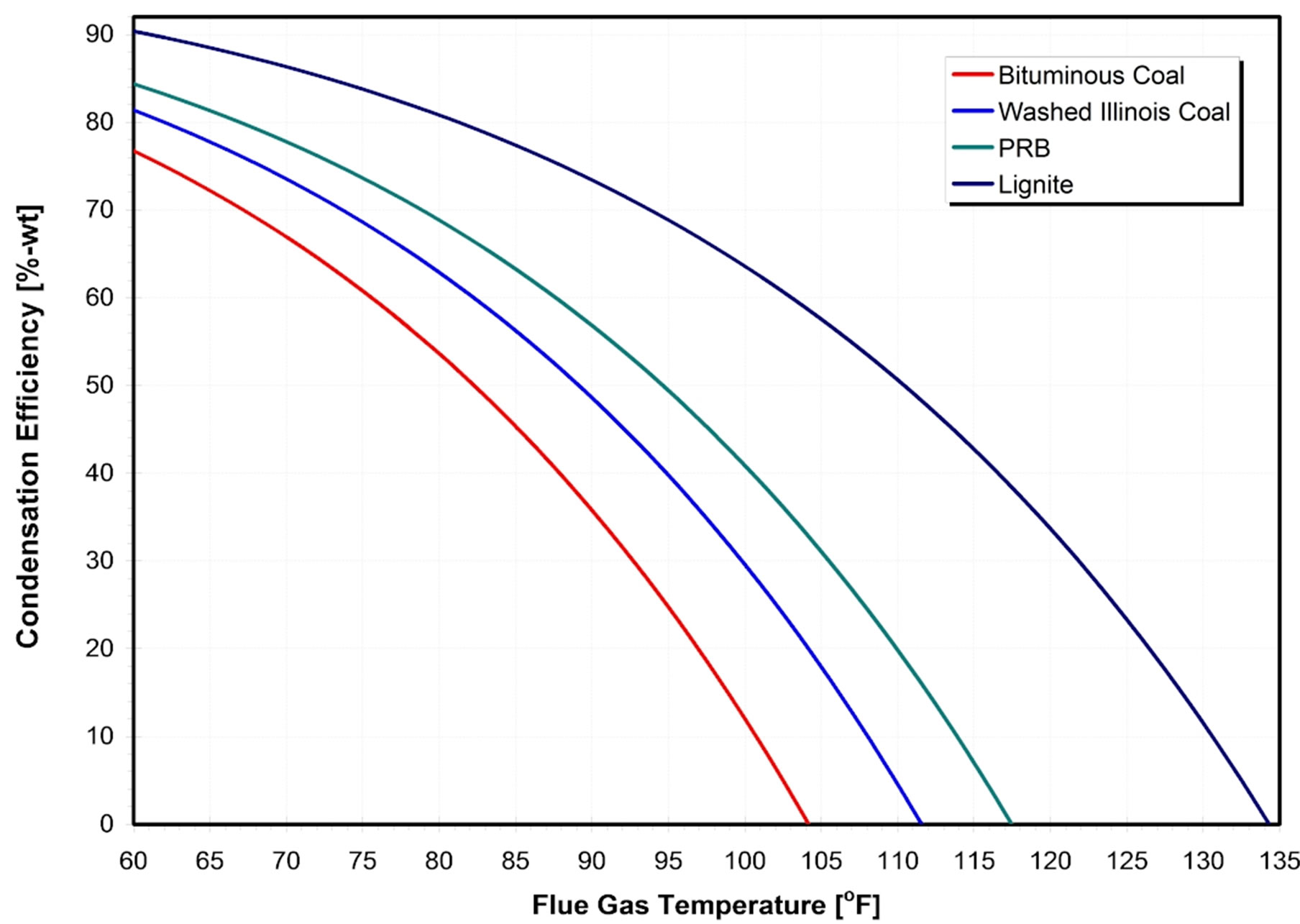
Figure 7. Condensing efficiency as a function of flue gas temperature.

Figure 8. Acid dew point temperature vs condensation.
the moisture content in the fuel is low, efficiency of the boiler can be as high as 80 percent.
REFERENCES
- N. Arai, H. Taniguchi, K. Mouri and T. Nakahara, “Exergy Analysis on Combustion and Energy Conversion Processes,” Energy, Vol. 30, No. 2-4, 2005, pp. 111-117. doi:10.1016/j.energy.2004.04.014
- A. Bejan, “Fundamentals of Exergy Analysis, Entropy Generation Minimization, and the Generation of Flow Architecture,” International Journal of Energy Research, Vol. 26, No. 7, 2002, pp. 545-565. doi:10.1002/er.804
- G. Tsatsaronis and M. Park, “On Avoidable and Unavoidable Exergy Destructions and Investment Costs in Thermal Systems,” Energy Conversion & Management, Vol. 43, No. 9-12, 2002, pp. 1259-1270. doi:10.1016/S0196-8904(02)00012-2
- T. J. Kotas, “Exergy Criteria of Performance for Thermal Plant: Second of Two Papers on Exergy Techniques in Thermal Plant Analysis,” International Journal of Heat and Fluid Flow, Vol. 2, No. 4, 1980, pp. 147-163. doi:10.1016/0142-727X(80)90010-7
- T. Ganapathy, N. Alagumurthi, R. P. Gakkhar and K. Murugesan, “Exergy Analysis of Operating Lignite Fired Thermal Power Plant,” Journal of Engineering Science and Technology Review, Vol. 2, No. 1, 2009, pp. 123- 130.
- S. C. Kamate and P. B. Gangavati, “Exergy Analysis of Cogeneration Power Plants in Sugar Industries,” Applied Thermal Engineering, Vol. 29, No. 5-6, 2009, pp. 1187- 1194. doi:10.1016/j.applthermaleng.2008.06.016
- A. Datta, S. Sengupta and S. Duttagupta, “Exergy Analysis of a Coal-Based 210 mw Thermal Power Plant,” International Journal of Energy Research, Vol. 31, No. 1, 2007, pp. 14-28.
- I. H. Aljundi, “Energy and Exergy Analysis of a Steam Power Plant in Jordan,” Applied Thermal Engineering, Vol. 29, No. 2-3, 2009, pp. 324-328. doi:10.1016/j.applthermaleng.2008.02.029