 Journal of Power and Energy Engineering, 2014, 2, 729-734 Published Online April 2014 in SciRes. http://www.scirp.org/journal/jpee http://dx.doi.org/10.4236/jpee.2014.24097 How to cite this paper: Liu, W.Y., et al. (2014) Thermo-Dynamical Analysis on Electricity-Generation Subsystem of CAES Power Plant. Journal of Power and Energy Engineering, 2, 729-734. http://dx.doi.org/10.4236/jpee.2014.24097 Thermo-Dynamical Analysis on Electricity-Generation Subsystem of CAES Power Plant Wenyi Liu, Gang Xu, Yongping Yang Key Lab of Education Ministry for Power Plant Equipments Conditions Monitoring and Fault Diagnosis, North China Electric Power University, Beijing, China Email: lwy @ncepu.edu.cn, xg2008@ncepu.edu.cn, yyp@ncepu.edu.cn Received January 2014 Abstract Besides pumped hydropower, Compressed Air Energy Storage (CAES) is the other solution for large energy storage capacity. It can balance fluctuations in supply and demand of electricity. CAES is essential part of smart power grids. Linked with the flow structure and dynamic characteristic of electricity generation subsystem and its components, a simulation model is proposed. The r- mo-dynamical performance on off-design conditions have been analyzed with constant air mass flux and constant gas combustion temperature. Some simulation diagrams of curve are plotted t oo. The contrast of varied operation mode thermal performance is made between CAES power plant and simple gas turbine power plant. Keywords Electricity Generation Sub-System; CAES Power Plant; Thermal Performance; Simulation Analysis; Off-Design Conditions 1. Introduction With the development of renewable energy, the grid load regulation problem is becoming more and more se- rious. Its performance is dependent on energy storage system because of the load fluctuation. Some problems can be solved by electrical energy storage system, for example the peak & off-peak demand of power generation, the improvement of reliability and steadiness of power supply [1] [2]. In CAES technology, air is compressed with a motor/generator using low cost, off-peak electricity and stored underground in caverns or porous media. This is called energy storage subsystem. This pressurized air is re- leased from the ground and then be mixed and burned with gas in a combustor. The hot expanding gases drive a turbo expander and run a motor/generator which, in turn, produces electricity during peak demand periods. This is the other subsystem, electricity generation subsystem. The electricity generation subsystem of CAES includes [3]: isobaric heating process in burner, adiabatic expanding process in turbo expander and isobaric heat release process. Main influence factors of practical thermo-dynamic processes including burning efficiency of burner η b, expansion efficiency of turbo expander and some performance parameters of flowing loss processes. Combined 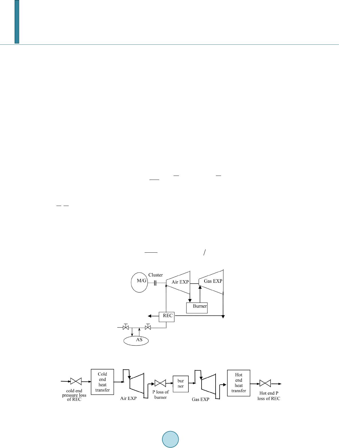 W. Y. Liu et al. with the characteristics of this subsystem and its components, an off-design condition simulation model is pro- posed based on unit’s modeling system. Equipments selection and their off-design condition characteristics are analyzed. 2. Simulation Modeling [4] [5] Turbo expander is key equipment of electricity generation subsystem for CAES. For the sake of utilizing high pressure air released from air storage dome, the air expander can be added before gas expander. At the same time, the re-heater and recuperator can be used in this subsystem. Figure 1 is the conceptual diagram of electric- ity generation subsystem. M/G is motor/generator, Air EXP is air expander, Gas EXP is gas expander, REC is recuperator and AS is air storage dome. The electricity generation subsystem can be divided to some modeling parts, as Figure 2. Model based on assumptions as follows: 1) air and gas is ideal air, 2) the specific heat of air is constant, 3) the flowing of air and heat transfer between air and wall is steady process, 4) η b is constant. The equations of these typical parts can be formulated. They include 6 differential equations. With considera- tion of practical conditions, the heat content of air and gas can be ignored, the compressibility of air and gas in recuperator can be ignored too. The equation for metal heat storage is Equation (1): ()( ) m wpggmam a dT cTT TT d ρδ αα τ ⋅⋅=− −− (1) δ—the thickness of recuperator wall αg, αa—hot end and cold end convection heat transfer coefficients —average temperature of air part and gas part ρw,Aw—density of wall and heat transfer area Based on , Δt = 75 K and K0 = 100 W/(m2·K) on design condition. The density of recuperator material is 7800 kg/ m3, specific heat cp = 460 J/(kg·K), αg = αa = α, so the time constant can be derived as Equation (2) on design condition: (2) Figure 1. The conceptual diagram of electricity gen- eration subsystem. Figure 2. Typical modeling parts of electricity generation subsystem. 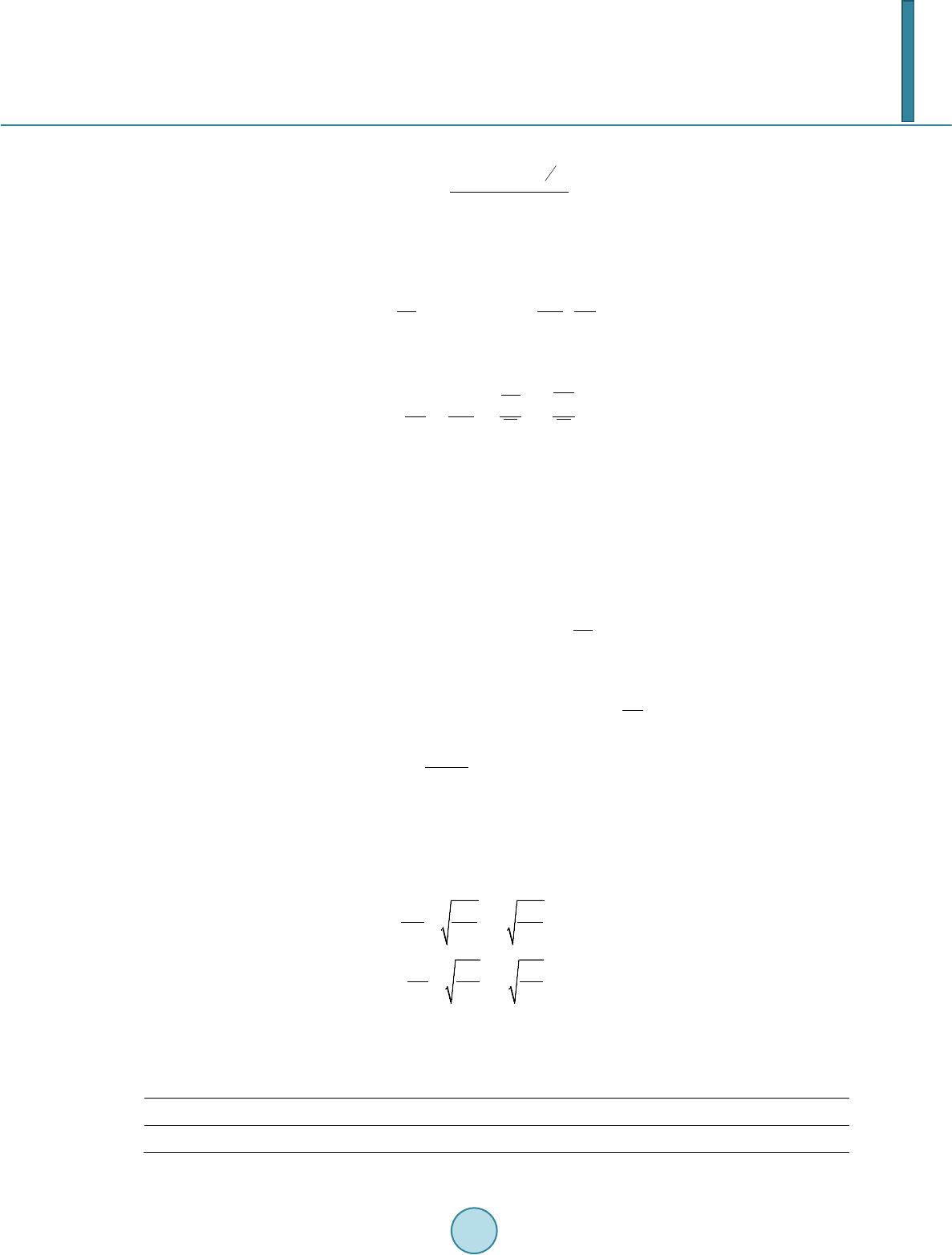 W. Y. Liu et al. The burning efficiency of burner can be expressed as Equation (3). 1.75 300 max max () T ba pADe fG η = (3) P, T—inlet pressure and inlet temperature of burner Amax, Dmax—maximum cross-section area and its diameter The off-design equations of recuperator is Equation (4) 0 00 00 1/[(1)()( )] a a GK GK σσσ σ = +− (4) Heat transfer coefficient K is associated with recuperator type and air flux, so the off-design formula can be expressed as Equation (5) 0 0.8 0.060.16 000 ()( )()) g aa aag T KG T KG TT = (5) 3. Off-Design Conditions Operation Simulation [4] PG9171E (GE) can be taken as simulation object, main parameters as Table 1. Some values are as follows: 1) Relative internal efficiency of gas expander is 0.905 (k = 1.33) and air expander is 0.88. 2) The pressure losses in burner, cold end of recuperate and hot end of recuperator are 3%, 1% and 3% respectively. LHV of fuel is 41,960 kJ/kg, working consuming for compressing air = 617.65 kJ/kg [4], outlet air pressure of air storage dome is 61bar, temperature is 30˚C. The additional formulations are as follows (6)-(9): 1 1 1 11211 1 0()(273)(1) k k pa paa cGtt cGt πη − − =⋅ ⋅− −⋅⋅+−⋅ (6) 23 12 0 () bfa fppa LHV GGGctcGt η = ⋅⋅−+⋅⋅+⋅⋅ (7) 2 2 1 234232 0() ()() (273)(1) k k p afpaft c GG ttc GG t πη − − =⋅+⋅−− ⋅+⋅+−⋅ (8) (9) t1, t2, —inlet T and outlet T of air expander. 0.85—the heat transfer efficiency of recuperator. A) Simulation calculations on design air flux, additional equation are as follows (10)-(12) [6] [7]: 234 112 [() ()()] epafp amg P cGGttcGtt ηη =⋅+⋅−+⋅ ⋅−⋅ (10) 00 0 (2 ) a asas a asas hh hh η η = − (11) 00 0 (2 ) t tsts t tsts hh hh η η = − (12) The calculation results are shown as Figures 3-5. Some conclusions can be drawn from figures. With the load lowered, the internal efficiency of air expander and gas expander is lowered obviously, heat rate of generating Table 1. Main performance parameters of gas turbine. Ty pe Pe (kW ) e (%) Pressure rati o Ga (kg/s) Initial T/t3 (˚C) Leakage T/t4 (˚C) Leakage air flus G4 (kg/s) PG9171E 123400 33.8 12.3 403.7 1124 538 412.4 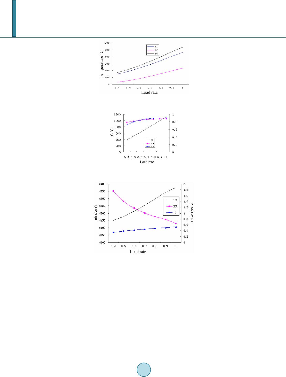 W. Y. Liu et al. Figure 3. t1, t2, t4 varying with load rate on design air flux. Figure 4. t3, ηa, ηt varying with load rate on design air flux. Figure 5. HR, ER, ξ varying with load rate on design air flu x. electricity is lowered, electricity rate of generating electricity is improved obviously, the energy transformation coefficient is lowered obviously too. B) Simulation calculations on design inlet temperature of gas expander. Some results are seen as Figures 6-8. Some conclusions are: with the load lowered, the internal efficiency of air expander and gas expander is constant approximately, heat rate and electricity rate of generating electricity are improved, the energy transformation coefficient is lowered a little. Some results are seen as Figures 6-8. Some conclusions are: with the load lowered, the internal efficiency of air expander and gas expander is constant approximately, heat rate and electricity rate of generating electricity are improved, the energy transformation coefficient is lowered a little. C) Contrast with off-design gas turbine performance. On the basis of off-design performance of gas turbine, using former selected gas turbine, the performance contrast diagram of gas turbine and electricity generation subsystem is shown in Figure 9 with the load scope 100% - 40%. 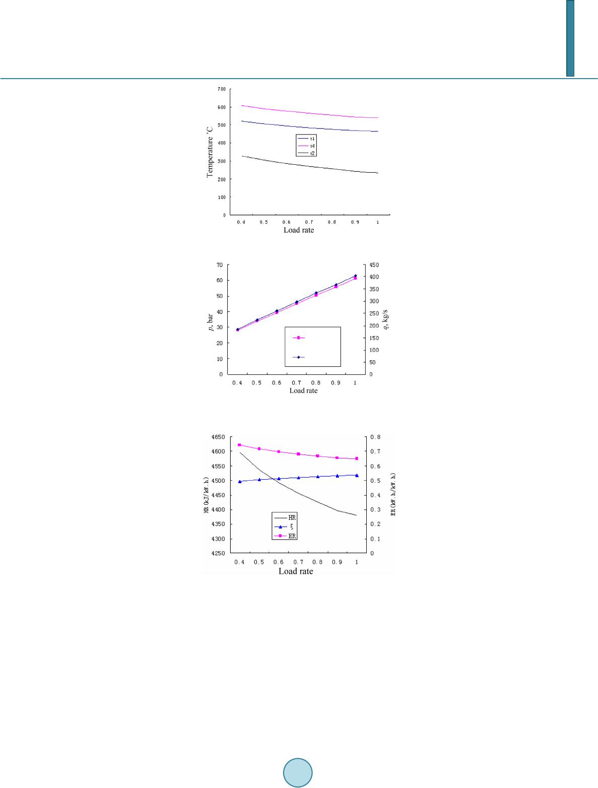 W. Y. Liu et al. Figure 6. t1, t2, t4 varying design inlet temperature. Figure 7. t3, ηa, ηt varying with load rate on design inlet temperature. Figure 8. HR, ER, ξ varying with load rate on design inlet temperature. It is obvious that thermal efficiency is varying from 33.8% to 0% of gas turbine power plant when load rate varying among 100% - 40%. But energy transform coefficient varies from 53.6% to 34.3% on design air flux, from 53.6% to 49.5% on design inlet temperature. 4. Conclusions 1) The electricity generation subsystem of CAES is divided into three processes, the difference between prac- tical process and ideal process is described and analyzed in this paper. 2) Combined with the characteristic of electricity generation subsystem and its components, a subsystem si- mulation model is proposed based on unit’s modeling system. 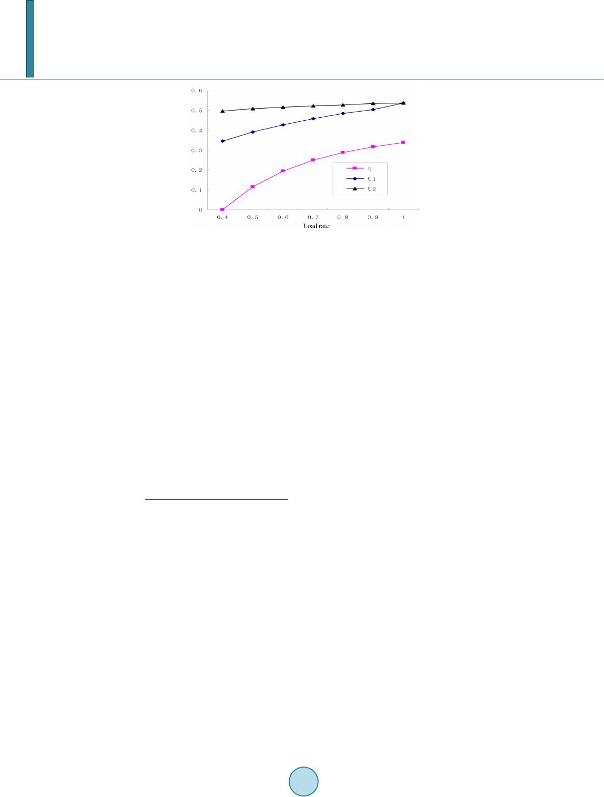 W. Y. Liu et al. Figure 9. η, ξ1, ξ2 varying with load rate. Η—thermal effi- ciency of gas turbine; ξ1—energy transform coefficient on de- sign air flux; ξ2—energy transform coefficient on design inlet temperatu re. 3) The simulation diagrams of off-design condition are plotted. The conclusion is that thermal efficiency is varying from 33.8% to 0% of gas turbine power plant when load rate varying among 100% - 40%. But energy transform coefficient varies from 53.6% to 34.3% on design air flux, from 53.6% to 49.5% on design inlet tem- perature. Acknowledgements The paper is supported by National Nature Science Fund of China (No. 51276059). Funding This work was supported by the Fundamental Research Funds for the Central Universities (No. 10MG11). References [1] Cavall o, A.J. (2011) Energy Storage Technologies for Utility Scale Intermittent Renewable Energy Systems. Transac- tions of the ASME, 123, 387-389. [2] Bake r, J.N. and Collison, A. (1999) Electrical Energy Storage at the Turn of Millennium. Power Engineering Journal, 107-112. http://dx.doi.org/10.1049/pe:19990301 [3] Li u, W.-Y., Yang, Y.-P. and Song, Z.-P. (2005) Optimization and Performance Simulation of Different CAES Sys- tems. Journal of Engineering Thermophysics, 26, 25-28. [4] Liu, W.-Y. Simulation Analysis of Thermal Performance for Compressed Air Energy Storage (CAES) Power Plant. Doctor Dissertation of North China Electric Power University, Beijing, 19-36. [5] Ni, W.-D., Xu, X.-D., Li, Z., et al. (1996 ) Some Problems of Thermal Power System Model and Control. 1st Edition, Beijing Science Press. [6] Li n, R.-M., Liu, R.-T., Jin, H.-G., et al. (20 04 ) Gas Turbine Selection Problems of Combined Cycle Power Plant. Gas Turbine Technology, 9, 6-13. [7] Zhang, N. and Cai, R.X. (2000 ) Off-Design Condition Typical Analytical Characters of Single-Axis Gas Turbine Com- bined Cycle. Journal of Engineering Thermophysics, 21, 529-532.
|