Paper Menu >>
Journal Menu >>
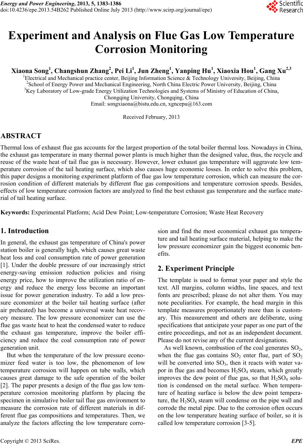 Energy and Power Engineering, 2013, 5, 1383-1386 doi:10.4236/epe.2013.54B262 Published Online July 2013 (http://www.scirp.org/journal/epe) Experiment and Analysis on Flue Gas Low Temperature Corrosion Monitoring Xiaona Song1, Changshun Zhang2, Pei Li1, Jun Zheng1, Yanping Hu1, Xiaoxia Hou1, Gang Xu2,3 1Electrical and Mechanical practice center, Beijing Information Science & Technology University, Beijing, China 2School of Energy Power and Mechanical Engineering, North China Electric Power University, Beijing, China 3Key Laboratory of Low-grade Energy Utilization Technologies and Systems of Ministry of Education of China, Chongqing University, Chongqing, China Email: songxiaona@bistu.edu.cn, xgncepu@163.com Received February, 2013 ABSTRACT Thermal loss of exhaust flue gas accounts for the largest proportion of the total boiler thermal loss. Nowadays in China, the exhaust gas temperature in many thermal power plants is much higher than the designed value, thus, the recycle and reuse of the waste heat of tail flue gas is necessary. However, lower exhaust gas temperature will aggravate low tem- perature corrosion of the tail heating surface, which also causes huge economic losses. In order to solve this problem, this paper designs a monitoring experiment platform of flue gas low temperature corrosion, which can measure the cor- rosion condition of different materials by different flue gas compositions and temperature corrosion speeds. Besides, effects of low temperature corrosion factors are analyzed to find the best exhaust gas temperature and the surface mate- rial of tail heating surface. Keywords: Experimental Platform; Acid Dew Point; Low-temperature Corrosion; Waste Heat Recovery 1. Introduction In general, the exhaust gas temperature of China's power station boiler is generally high, which causes great waste heat loss and coal consumption rate of power generation [1]. Under the double pressure of our increasingly strict energy-saving emission reduction policies and rising energy price, how to improve the utilization ratio of en- ergy and reduce the energy loss become an important issue for power generation industry. To add a low pres- sure economizer at the boiler tail heating surface (after air preheated) has become a universal waste heat recov- ery measure. The low pressure economizer can use the flue gas waste heat to heat the condensed water to reduce the exhaust gas temperature, improve the boiler effi- ciency and reduce the coal consumption rate of power generatio n un i t. But when the temperature of the low pressure econo- mizer feed water is too low, the phenomenon of low temperature corrosion will happen on tube walls, which causes great damage to the safe operation of the boiler [2]. The paper presents a design of the flue gas low tem- perature corrosion monitoring platform by placing the specimen in simulative boiler tail flue gas enviro nment to measure the corrosion rate of different materials in dif- ferent flue gas compositions and temperatures. Then, we analyze the factors affecting the low temperature corro- sion and find the most economical exhaust gas tempera- ture and tail heating surface material, help ing to make the low pressure economizer gain the biggest economic ben- efits. 2. Experiment Principle The template is used to format your paper and style the text. All margins, column widths, line spaces, and text fonts are prescribed; please do not alter them. You may note peculiarities. For example, the head margin in this template measures proportionately more than is custom- ary. This measurement and others are deliberate, using specifications that anticipate your paper as one part of the entire proceedings, and not as an independent document. Please do not revise any of the curr ent designations. As well known, combustion of the coal generates SO 2, when the flue gas contains SO2 enter flue, part of SO2 will be converted into SO3, then it reacts with water va- por in flue gas and becomes H2SO4 steam, which greatly improves the dew point of flue gas, so that H2SO4 solu- tion is condensed on the metal surface. When tempera- ture of heating surface is below the dew point tempera- ture, the H2SO4 steam will condense on the pipe wall and corrode the metal pipe. Due to the corrosion often occurs on the low temperature heating surface of boiler, so it is called low temperature corrosion [3-5]. Copyright © 2013 SciRes. EPE 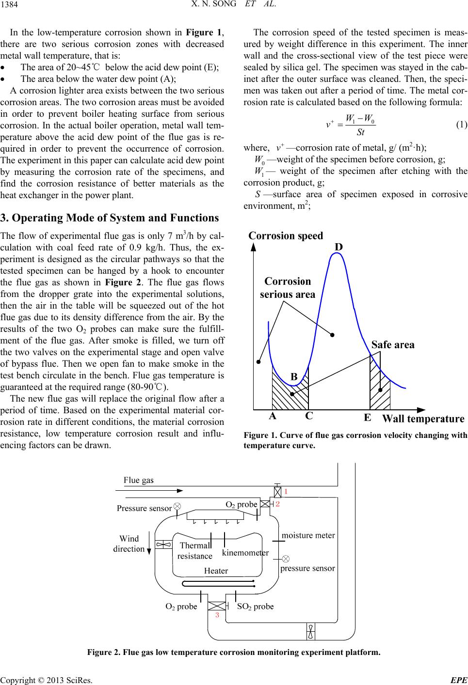 X. N. SONG ET AL. 1384 In the low-temperature corrosion shown in Figure 1, there are two serious corrosion zones with decreased metal wall temperature, that is: The area of 20~45℃ below the acid dew point (E); The area below the water dew point (A); A corrosion lighter area exists between the two serious corrosion areas. The two corrosion areas must be avoided in order to prevent boiler heating surface from serious corrosion. In the actual boiler operation, metal wall tem- perature above the acid dew point of the flue gas is re- quired in order to prevent the occurrence of corrosion. The experiment in this paper can calculate acid dew poin t by measuring the corrosion rate of the specimens, and find the corrosion resistance of better materials as the heat exchanger in the power plant. 3. Operating Mode of System and Functions The flow of experimental flue gas is only 7 m3/h by cal- culation with coal feed rate of 0.9 kg/h. Thus, the ex- periment is designed as the circular pathways so that the tested specimen can be hanged by a hook to encounter the flue gas as shown in Figure 2. The flue gas flows from the dropper grate into the experimental solutions, then the air in the table will be squeezed out of the hot flue gas due to its density difference from the air. By the results of the two O2 probes can make sure the fulfill- ment of the flue gas. After smoke is filled, we turn off the two valves on the experimental stage and open valve of bypass flue. Then we open fan to make smoke in the test bench circulate in the bench. Flue gas temperature is guaranteed at the required r a nge (80-90℃). The new flue gas will replace the original flow after a period of time. Based on the experimental material cor- rosion rate in different conditions, the material corrosion resistance, low temperature corrosion result and influ- encing factors can be drawn. The corrosion speed of the tested specimen is meas- ured by weight difference in this experiment. The inner wall and the cross-sectional view of the test piece were sealed by silica gel. The specimen was stayed in the cab- inet after the outer surface was cleaned. Then, the speci- men was taken out after a period of time. The metal cor- rosion rate is calculated based on the following formula: 10 WW vSt (1) where, v —corrosion rate of metal, g/ (m2·h); 0 W W—weight of the specimen before corrosion, g; 1— weight of the specimen after etching with the corrosio n pr oduct, g; S—surface area of specimen exposed in corrosive environment, m2; Figure 1. Curve of flue gas corrosion velocity changing with temperature curve. Figure 2. Flue gas low temperature corrosion monitoring experiment platform. Copyright © 2013 SciRes. EPE  X. N. SONG ET AL. 1385 t—time of specimen corrosion, h. The experimental platform can achieve a variety of functions: (1) To determine the general range of acid dew point based on the corrosion rate of materials; (2) To find the most appropriate temperature of flue gas emissions; (3) To identify the factors affecting the low-tem- premature corrosion; Help to find the better heat exchanger material with nice corrosion resistance. 4. Design of Experiment Platform 4.1. Design of Experiment Platform Noumenon The material of experiment platform noumenon is made of stainless steel with thickness of 5mm, width of 900mm and height of 600 mm. The shape is ring with the diameter of 130 mm; the top of the experiment box is a rectangle of 250*250 mm. There exists a bypass flue near the entrance of the incoming flue gas. The flue gas can be discharged if experiment is aborted. In the experiment box there are two rows of hooks for hanging specimen, the hooks are coated by silicone rub- ber to prevent metal hooks and specimen from reaction. The positive of experiment box is a sealed glass door, which is easy to take or put specimen and observe inter- nal situation of experiment box. There is a fan in the experiment platform to provide power for flue gas circulation. The designed wind speed in the experiment box is 7 m/s. By using the cross sec- tional area, the fan air volume is calculated as 1575 m3 / h. A heater is put at the bottom of the experiment table. When the flue gas temperature is lower than the expected value range, the control system will co ntrol heater work- ing until flue gas temperature value reach to the upper limit. Power capacity of the heater is 1 kW. 4.2. Design of the Data Acquisition System This experiment acquires the following parameters: flue gas temperature, humidity, pressure, flow rate, the con- centration of O2 and SO2. There are corresponding equipments around the experiment platform: in the ex- periment box, thermal resistance is installed to measure the flue gas temperature, the pressure sensor is installed to measure the pressure of the experiment box, the ki- nemometer to is installed to measure the velocity of flue gas and the O2 probe is installed to measure the concen- tration of O2; in the pipe at the side of the experiment platform the moisture meter is installed to measure flue gas humidity; at the bottom of the experiment platform O2 and SO2 probes are installed to measure the concen- tration of O2 and SO2. 4.3. Design of the Control System The feedback control is adopted. For example, the con- trol function that applied to the controlled device is to use the feedback information to constantly correct the deviation of controlled volume. Besides, the control sys- tem adopts programmable logic controller (PLC) auto- matic control system. The control process of PLC auto- matic control system is usually divided into three stages, namely input sampling, the user program execution and output refresh. The completion the above three stages is called a scan cycle. During the whole operation period, the CPU of PLC repeats the above three stages to a cer- tain scanning speed. The basic control step of a typical PLC automatic con- trol system is shown in Figure 3: As shown in the Figure 3, the sensor transmitter de- tects the parameters of the controlled object, and sends input signal to the PLC. The analog signal is converted into a digital signal by A / D converter. The CPU deliv- ers a digital signal to the actuator after operating the user program, which is converted into analog signal by D / A converter. The controlled objects act according to the instructions. The control flow of this experiment table can be sum- marized as: 1) When PLC power-on button is pressed the valve 1 is closed while valve 2, 3 is open and flue gas fills into the experiment table. At this moment, the pressure sensor, gas composition probe, thermal resistance, flow meter and hygrometer work; 2) When the detected results of O2 probe installed above and below are about the same, we close the valve 2, 3 and open the valve 1; after that, we operate the PLC program and open the fan. At the same time, the pressure sensor, gas composition probe, heat resistance, kinem- ometer and hygrometer continue to work. PLC controls the heater to start or stop and general power of experi- ment table is based on the sensor sign al; 3) Since the upp er pressur e limit is 1kPa, the op eration will automatically stop if this value is exceeded and the Figure 3. The basic control step of the typical PLC automatic control system. Copyright © 2013 SciRes. EPE 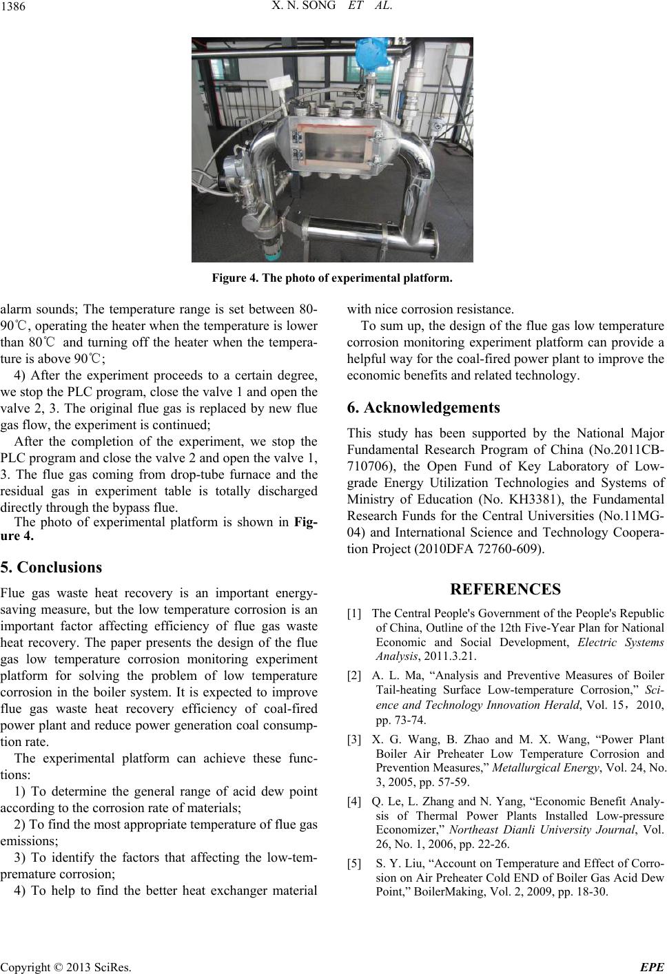 X. N. SONG ET AL. 1386 Figure 4. The photo of experimental platform. alarm sounds; The temperature range is set between 80- 90℃, operating the heater when the temperature is lower than 80℃ and turning off the heater when the tempera- ture is above 90℃; 4) After the experiment proceeds to a certain degree, we stop the PLC program, close the valve 1 and open the valve 2, 3. The original flue gas is replaced by new flue gas flow, the experiment is continued; After the completion of the experiment, we stop the PLC program and close the valve 2 and open the valve 1, 3. The flue gas coming from drop-tube furnace and the residual gas in experiment table is totally discharged directly through the bypass flue. The photo of experimental platform is shown in Fig- ure 4. 5. Conclusions Flue gas waste heat recovery is an important energy- saving measure, but the low temperature corrosion is an important factor affecting efficiency of flue gas waste heat recovery. The paper presents the design of the flue gas low temperature corrosion monitoring experiment platform for solving the problem of low temperature corrosion in the boiler system. It is expected to improve flue gas waste heat recovery efficiency of coal-fired power plant and reduce power generation coal consump- tion rate. The experimental platform can achieve these func- tions: 1) To determine the general range of acid dew point according to the corrosion rate of materials; 2) To find the most appropriat e temperature of flue gas emissions; 3) To identify the factors that affecting the low-tem- premature corrosion; 4) To help to find the better heat exchanger material with nice corrosion resistance. To sum up, the design of the flue gas low temperature corrosion monitoring experiment platform can provide a helpful way for the coal-fired power plant to improve the economic benefits and related technology. 6. Acknowledgements This study has been supported by the National Major Fundamental Research Program of China (No.2011CB- 710706), the Open Fund of Key Laboratory of Low- grade Energy Utilization Technologies and Systems of Ministry of Education (No. KH3381), the Fundamental Research Funds for the Central Universities (No.11MG- 04) and International Science and Technology Coopera- tion Project (2010DFA 72760-609). REFERENCES [1] The Central People's Government of the People's Republic of China, Outline of the 12th Five-Year Plan for National Economic and Social Development, Electric Systems Analysis, 2011.3.21. [2] A. L. Ma, “Analysis and Preventive Measures of Boiler Tail-heating Surface Low-temperature Corrosion,” Sci- ence and Technology Innovation Herald, Vol. 15,2010, pp. 73-74. [3] X. G. Wang, B. Zhao and M. X. Wang, “Power Plant Boiler Air Preheater Low Temperature Corrosion and Prevention Measures,” Metallurgical Energy, Vol. 24, No. 3, 2005, pp. 57-59. [4] Q. Le, L. Zhang and N. Yang, “Economic Benefit Analy- sis of Thermal Power Plants Installed Low-pressure Economizer,” Northeast Dianli University Journal, Vol. 26, No. 1, 2006, pp. 22-26. [5] S. Y. Liu, “Account on Temperature and Effect of Corro- sion on Air Preheater Cold END of Boiler Gas Acid Dew Point,” BoilerMaking, Vol. 2, 2009, pp. 18-30. Copyright © 2013 SciRes. EPE |