Z. F. CHU ET AL. 1173
The basic principles of the conventional voltage bal-
ancing method are introduced in [1] as follows.
All of voltages of sub-module capacitors in the
same arm are sorted according to the order from
lower to higher or from higher to lower.
When the arm current charges the capacitors,
sub-module whose capacitor voltage is lower is
switched on and sub-module whose capacitor volt-
age is higher is switched off.
When the arm current discharges the capacitors,
sub-module whose capacitor voltage is higher is
switched on and sub-module whose capacitor volt-
age is lower is switched off.
The conventional voltage balancing method needs to
sort all capacitor voltages in the same arm each control
period. If the number of sub-modules in each arm is very
large, the sorting time can occupy a large pro portion.
3. The Novel Voltage Balancing Method for
SUPWM Method for MMC
The novel voltage balancing method is derived from the
conventional voltage balancing method. The basic prin-
ciples of the novel voltage balancing method are pre-
sented as follows.
The sub-modules in each arm are divided into
several equal groups. For example, if the number
of sub-modules in each arm is 20 and the number
of groups can be selected as 5, each group can
have four sub-modules. Sub-modules 1, 2, 3 and
4 can be assigned to group1, sub-modules 5, 6, 7
and 8 can be assigned to group2, sub-modules 9,
10, 11 and 12 can be assigned to group3, sub-
modules 13, 14, 15 and 16 can be assigned to
group4 and sub-modules 17, 18, 19 and 20 can be
assigned to group 5.
The voltages of sub-module comparators in each
group are sorted according to the order from low-
er to higher or from higher to l ower.
The average voltage of each group is computed
and the average voltages in each arm are sorted
according to the order from lower to higher or
from higher to lower.
According to the arm current and the number of
sub-modules which are needed to switch on, the
groups are labeled by 1 (all of sub-modules in this
group are switched on), 2 (some of sub-modules
in this group are switched on) and 3 (all of
sub-modules in this group are switched off).
When the arm current is charging capacitors, the
label of group whose average voltage is lower is 1
or 2 and the label of group whose average voltage
is higher is 2 or 3. When the arm current is dis-
charging capacitors, the label of group whose av-
erage voltage is higher is 1 or 2 and the label of
group whose average voltage is lower is 2 or 3.
For example, if the sorting result of average volt-
ages is group 4>group 3>group 5>group 1>group
2, the arm current is charging the capacitors and
the number of sub-modules which are needed to
switch on is 10, the labels of group 2 and group1
will be 1, the lab el of group5 will be 2 and the la-
bels of group 3 and group 4 will be 3.
The sub-modules in each group will be switched on or
off based on the sorting result of the capacitor voltages in
group, the label of group, the arm current and the number
of sub-modules which are needed to switch on. If the
label of group is 1 (or 3), all of sub-modules in this group
are switched on (or switched off). When the arm current
is charging capacitors and the label of group is 2,
sub-module whose capacitor voltage is lower is switched
on and sub-module whose capacitor voltage is higher is
switched off. When the arm current is discharging ca-
pacitors and the label of group is 2, sub-module whose
capacitor voltage is higher is switched on and the
sub-module whose capacitor voltage is lower is switched
off. For example, if the arm current is charging capaci-
tors, the number of sub-modules which are needed to
switch on is 10, the labels of group 2 and group 1 are 1,
the label of group 5 is 2, the labels of group3 and group 4
are 3 and the sorting resu lt of capacitor voltage s of group
5 is SM20>SM18>SM17>SM19, all of sub-modules in
group 2 and group 1 are switched on, all of sub-modules
in group 3 and group 4 are switched off, SM17 and SM19
are switched on and SM20 and SM18 are switched off.
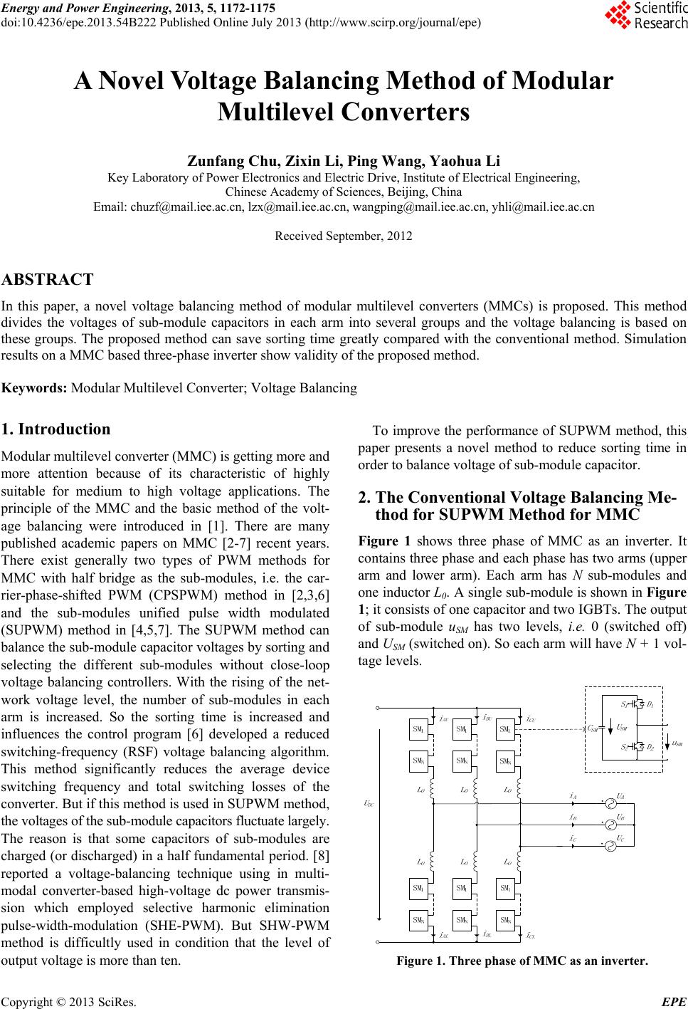
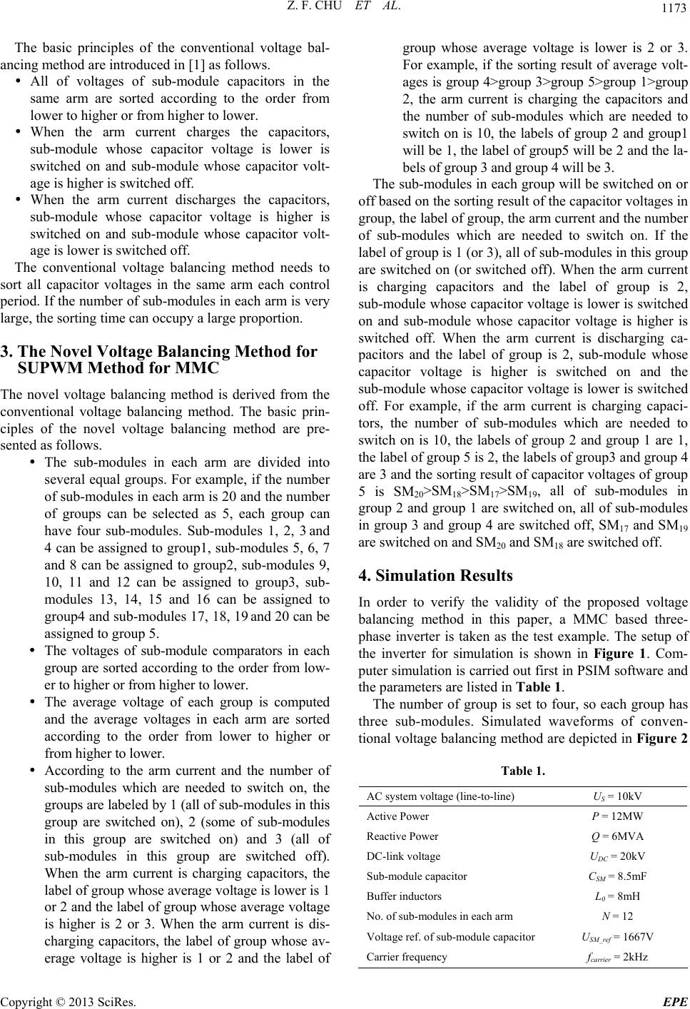
4. Simulation Results
In order to verify the validity of the proposed voltage
balancing method in this paper, a MMC based three-
phase inverter is taken as the test example. The setup of
the inverter for simulation is shown in Figure 1. Com-
puter simulation is carried out first in PSIM software and
the parameters are listed in Table 1.
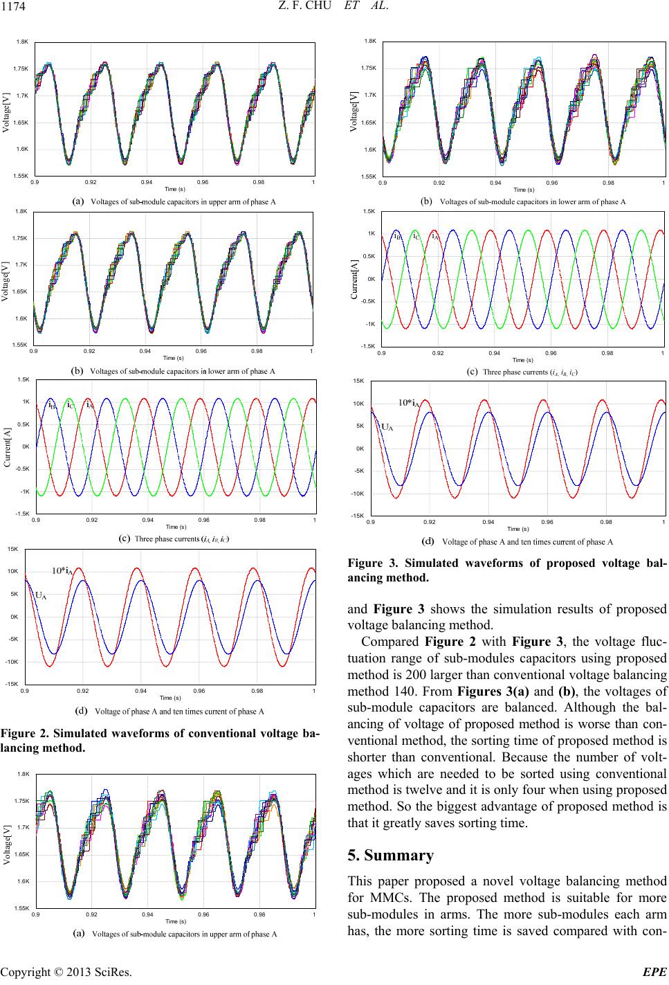
The number of group is set to four, so each group has
three sub-modules. Simulated waveforms of conven-
tional voltage balancing method are depicted in Figure 2
Table 1.
AC system voltage (line-to-line) US = 10kV
Active Power P = 12MW
Reactive Power Q = 6MVA
DC-link voltage UDC = 20kV
Sub-module cap a ci t o r CSM = 8.5mF
Buffer inductors L0 = 8mH
No. of sub-modules in each arm N = 12
Voltage ref. of su b -module capacitor USM_ref = 1667V
Carrier frequency fcarrier = 2kHz
Copyright © 2013 SciRes. EPE