Paper Menu >>
Journal Menu >>
 J. Software Engineering & Applications, 2010, 3, 1067-1079 doi:10.4236/jsea.2010.311126 Published Online November 2010 (http://www.SciRP.org/journal/jsea) Copyright © 2010 SciRes. JSEA 1067 A Tile Logic Based Approach for Software Architecture Description Analysis Aïcha Choutri1, Faiza Belala1, Kamel Barkaoui2 1LIRE Laboratory, University Mentouri of Constantine, Constantine, Algeria; 2CEDRIC, Conservatoire National des Arts et Métiers, Paris, France. Email: aichachoutri@gmail.com, belalafaiza@hotmail.com, kamel.barkaoui@cnam.fr Received July 13th, 2010; revised August 31st, 2010; accepted September 3rd, 2010. ABSTRACT A main advantage of Architecture Description Languages (ADL) is their aptitude to facilitate formal analysis and veri- fication of complex software architectures. Since some researchers try to extend them by new techniques, we show in this paper how the use of tile logic as extension of rewriting logic can enforce the ability of existing ADL formalisms to cope with hierarchy and composition features which are more and more present in such software architectures. In or- der to cover ADL key and generic concepts, our approach is explained through LfP (Language for rapid Prototyping) as ADL offering the possibility to specify the hierarchical behaviour of software components. Then, our contribution goal is to exploit a suitable logic that allows reasoning naturally about software system behaviour, possibly hierarchi- cal and modular, in terms of its basic components and their interactions. Keywords: Tile Logic, LfP Model, Software Architecture, Hierarchical Composition 1. Introduction Software Architecture (SA) has emerged as a principle method of understanding and developing high level structures of complex software systems. Nowadays, SA artifacts are becoming the foundation for building families of such systems. Then, the problem of ensuring as early as possible the correctness of an SA occupies increasing importance in the development life-cycle of software products. Formal approaches should be used to describe software architectures and express their dynamic evolution so that one could reason on them. Over past two decades there has been considerable research devoted to modeling and analysis of software architectures; among other, architecture description languages (or ADL) as suitable notation for SA formal specification. Their common advantage is their impressive body representation of evidence about the utility of architectural modeling and analysis [1]. Some of them attempted to provide behavioral modeling and analysis via numerous complementary behavioral formalisms. However, the most of applied approaches share the goal of defining mismatches in component composition. Recently, some researchers in industry and academia try to extend these ADL, by new techniques to analyze and validate architectural choices, both behavioral and quantitative, complementing traditional code-level analysis technique [2]. According to this motivation, we show through this paper how the tile logic as extension of rewriting logic can support ADL artifacts allowing and enforcing formal reasoning on software system behavior and dynamics. In particular, we show that tile system is closely joined to important inherent aspects of ADL, especially hierar- chical behavior of components and compositional one. We explain our proposed approach concretely through LfP architecture description language [3] as ADL offering the possibility to specify the hierarchical behavior of soft- ware components (in terms of LfP-BD diagrams) in addition to their structure that can be also of hierarchical nature (LfP-AD). Tile Logic [4] has been introduced for modular description of open, distributed and interactive systems. It constitutes a rewriting logic [5] extension taking into account rewriting with side effects and rewriting synchronization. So, it supports modular specification of concurrent system behaviors, their interaction and synchronization semantics thanks to its particular rules of rewrite called tiles. These rules can be instantiated with special terms in a given context. The main idea behind this  A Tile Logic Based Approach for Software Architecture Description Analysis 1068 logic is to impose dynamic restraints on terms to which a rule may be applied by decorating rewrite rules with observations ensuring synchronizations and describing interactions. Authors of [6,7] have proposed a mapping approach of LfP architectural description into rewriting logic in order to formalize its semantics and exploit this latter for hierarchical verification of some properties using model checking. The interest of such approach is the well care in purely formal way of concurrency in a distributed configuration through executable specification. In this paper, we use Tile logic strength the results obtained in [6,7] related to formalization and verification of LfP software architecture description via rewriting logic and its Maude language. Hence, owing to tile logic elements, we can deal with and preserve naturally the hierarchical structure and the hierarchical behavior of SA. Besides, executable specification of tile systems may be naturally defined by mapping tile logic into rewriting logic which is a semantic basis of several language implementations. In particular the proposed model implementation requires developing a set of strategies to control rewriting by discarding compu- tations that do not correspond to any deduction in tile logic. In the remainder of this paper, Section 2 situates our work among analogous ones in order to better surround its problematic. Section 3 is devoted to summarize basic concepts of tile logic. In Section 4, we present our approach to map an architectural description into tile logic. It is then explained and illustrated in Section 5 through LfP language. So, a successful classic case study of Producer/Consumer system is considered to show how we proceed to clutch tile logic to software architecture description language. Some comments evaluating our contribution are presented in Section 6. Last section concludes our work and gives its perspectives. 2. Contribution Setting It is not a novel idea to give a formal specification for software architecture. Most of existing ADL concentrates on providing a precise mathematical semantics for software architecture description of a system. All well known semantic formalisms for ADL give limitation when software architectures deal not only with structural aspects but also with behavioral ones. Besides, hierarchy concept, synchronization and reconfiguration ones restrict the use of these ADL formalisms. In the case of Rapid [8] for example, based on POSets (Partially Ordered event Sets), only architectural components interactions are formalized in addition to the architectural elements. Also, Wright [9] uses a subset process algebra named CSP (Communicating Sequential Processes) formal notation to describe partially components abstract behavior in a simple manner. Recent related works focus on defining rewriting logic based model for some existing ADL. For example, authors in [10] define a mapping of CBabel concepts into rewriting logic. A particular attention has been given to specify syntactic constructs semantic of this ADL example. LfP [3] integrating UML notations and state/transition automaton has been considered by the work of to associate to each of its views (LfP-AD and LfP-BD diagrams) possibly hierarchical an appropriate semantic meaning based on rewriting logic too. In fact, rewriting logic has been recognized as a semantic framework to model software system architecture. However, complexity of such systems structure and behavior induces rewriting logic flat models that do not preserve compositional and hierarchical features of ADL, so they are often difficult to manage. In this paper, we will show that tile logic based model, even if it is more complex to grasp, is much more appropriate and efficient. Tile logic is an extension of rewriting logic, supporting modular description of concurrent system behaviors, and their interaction and synchronization semantics. These assets delegate it as being the most suitable formalism to support semantic of more complex ADL, namely those having the possibility to describe hierarchical and mo- dular specification of distributed and open architectural applications such as LfP descriptions. In particular, both static and dynamic views of LfP architecture are naturally translated according to the tile system structure (space), and its computation flow (time), preserving hierarchical and compositional nature of this architectural description. Furthermore, this tile model may be then successfully exploited to formal reasoning on such descriptions and their analysis. 3. Tile Logic In this section, we recall some fundamental concepts of the underlying semantic framework, namely tile logic. More interested readers may consult [4]. Tile Logic has been introduced for modular description of open, distributed and interactive systems. This formalism reminiscent to term rewriting and concurrency theory, constitutes a rewriting logic [5] extension taking into account rewriting with side effects and rewriting synchronization. Although, ordinary format of rewrite rules allows state changes expression and concurrent calculus in a natural manner, it lacks tools to express interactions with the environment, i.e., rewrite rules can be freely instantiated with any term in any context. The main idea behind tile logic is to impose dynamic restraints on terms to which a rule may be applied by decorating rewrite rules with observations ensuring C opyright © 2010 SciRes. JSEA  A Tile Logic Based Approach for Software Architecture Description Analysis Copyright © 2010 SciRes. JSEA 1069 synchronizations and describing interactions. gory, the superposition of these two categories of cells The obtained rules are then called tiles, defining the behavior of partially specified components, called configurations, in terms of actions related to their input and output interfaces (the possible interactions with the internal/external environment). Each tile, having one of the forms in Figure 1, ex- presses that initial configuration s evolves to the final configuration t via the tile , producing the effect b, which can be observable by the rest of the system. Such a rewriting local step is allowed, only if the sub-compo- nents of s (its arguments) evolve to the sub-components of t producing an effect a, which acts as a trigger for α application. Arrows s and t of the tile α (in Figure 1) are called configurations (system states). They are algebraic structures equipped with operations of parallel and sequential composition. Each system configuration has both input and output interfaces responsible of system interactions with the environment. , ould be considered as a natural model for tile system. x, y the in t interfaces and, w, z the output interfaces. on- fig 4. Tile Logic for Architecture Description and an internal behavior, specified by a set of tiles, to sh Definition 1. A tile system is a 4-tuple T = (H, V, N, R) where H, V are monoïdal categories with the same set of objects OH = OV, N being a set of rule names and R: N→ H x V x V x H a function where for each α in N, if R(α) = (s, a, b, t), then s:x y, a:x w, b:y z and t: w z, for suitable objects x, y, z and w; with pu Auxiliary tiles set may be necessary to specify consis- tent interfaces rearrangements. A standard set of infer- ence rules (Figure 2) allows building larger rewriting steps, by composing tiles freely via horizontal (through side effects), vertical (computational evolution of c uration) and parallel (concurrent steps) operations. In the recent literature, tiles representing an extension of the SOS specification approach are designed for deal- ing with open states. They seem apt for many current applications [11-13]. Indeed, they have been used with success to model in detail several application classes such as coordination languages (triggers and effects represent coordination protocols) and software architecture styles [13,14]. This paper contributes to another meaningful and interesting application of Tile logic, it generalizes the approach proposed in [15] by defining a common formal Arrows a and b decorating tile α (in Figure 1) are also algebraic structures, they define observable effects (actions) for coordinating local rewrites through confi- guration interfaces (input and output ones). In general, configurations and observations give rise to two categories having the same class of objects (inter- faces). The former (horizontal so-called configuration) defines effects propagation; the latter (vertical so-called observations) describes state evolution. Then, double cate- model based on tile logic for architecture descriptions. Languages Tile logic has been exploited as a common semantic framework to define both abstract software architectures and their behaviors [16]. Generally, each component in a distributed system specification is described by a set of external ports, ensuring interactions with the environment or :a b st x y a b w z s t x, y: initial and final input interfaces w, z: initial and final output interface Figure 1. A tile representation. Rules generating the basic tiles, horizontal and vertical identities: R()=(s,a,b,t) :a t :x y H :Hx id tt y a : x z V :Va id xz a s t b Horizontal, vertical and parallel compositions : : ab s th f bc : ; ; a s htf c a :st :t b ch d ; : ; ac :: ac s th f bd : sac htf bd s h bd Figure 2. Inference rules.  A Tile Logic Based Approach for Software Architecture Description Analysis 1070 a deliver component functionalities. It is define cess and Fundamental SincDL, a complete software architectur that could be eithe co ociated mainly to (internal) description given by a tile ng, we present the four essential steps o til tep 1: Each software architectural Config ura tion in- rizontal and vertical categories are formed (see tion) that are ded/required ting hidden sub components model Configura- tiTS for a given architectural configuration Con- ntation deduced from their partial description. gCset, MsgCget provided computation component name with a at formalize s (1) (2) d by a tile tion. Its ho system, where objects of the two categories correspond to component interfaces. Vertical category (observations) defines its possible actions corresponding to component required/provided services and horizontal category gen- erates all component possible configurations. Gathered together via a set of tiles, horizontal and vertical catego- ries define expected behavior of the underlying compo- nent. Starting from a basic set of tiles and deduction rules of this logic, system global behavior defined as a coordi- nated evolution of its subcomponents, is naturally de- duced. We take in what follows all these ideas formulated through a generic semantic framework applicable for ADL either their semantics. It will be then applied on a specific case study. 4.1. Modeling Pro Definitions e in existing Ae tiles formalize binding connection. Some auxiliary tiles may be added to these basic tiles in order to deal with some particular ADL connection aspects like dynamic connection (components synchroni- zation) as it is the case for parameterized dynamic connection tiles defined in [16]. Definition 2. A tile system based description has to consider static architectural configura- tion and dynamic evolution (behavior) of software system, our proposed model follows the same separation of con- cerns. Two distinct, but not completely independent views are considered. For the first one, expressed by a set of existing components, connectors (often considered as particular components) and connection topology, we associate a tile system integrating these components (and connectors) definitions. In the second view, state transi- tion system, which is usually devoted to define compo- nent and system behavior, is extended and formally de- fined in the context of tile logic. Then, a software component,r a connection points. Morphisms of VConf-TS are simplified to design only two types of services: Ms mputation component or a connector, may have two definitions according to its granularity: A partial (external) description, ass o its interface, evolving an abstract data type for each component type (sort, operations and their pro- perties). A detailed c system formalizing both structure and behavior component. Computation or storage component may be either primitive or composite. For later case, the associated tile system is a composition of a set of hierarchical sub tile systems. If the component is a connector (communication entity), the associated tile system defines the corresponding communication protocol. In the followif binding connection deduced from configuration topology-connection. Two general forms of tiles can be defined here: 1' 12 : MsgC set CC s e model generation for any software architecture description: S volves an associated tile system Configuration–TS defini- Definition 2) by the involved architectural elements (components, connectors, ports, etc.). Morphisms of the horizontal category formalize connection points (in Configura characterized by essentially components names and interfaces, in terms of algebraic terms. On the other hand, morphisms of the vertical category (observations) formalize provi components services. Both categories have the same set of objects that are algebraic terms represen models that will be described at the next lower level. The set of tiles expresses configurations evolution and its propagation over all sub-components. These on- figuration = (Components, toplogy-connection) is de- fined by the 4-tuple (HConf-TS, VConf-TS, NConf-TS, RConf-TS) such that: OConf-TS is composed of all components abstract represe Morphisms of HConf-TS are formed upon algebraic terms specifying component interfaces intervening in r required by a component of name C under a message form. NConF-TS is the set of tile names. Each one is obtained by combining a ommunication component name. If there is no explicit connector (i.e., case of dynamic connector), the second name will be that of other computation component connected to the first one. RConf-TS: NConf-TS → H Conf-TS × VConf-TS VConf-TS HConf-TS is a function defining tiles th 1 1 2 MsgC get 2' 23 22 3 :MsgCget CC ss MsgC set C opyright © 2010 SciRes. JSEA  A Tile Logic Based Approach for Software Architecture Description Analysis 1071 s1, s1’, s2, s2’ are configurations, i.e. morphisms of HConf-TS, C1, C3 are computation com C2 is a connector name and MsgC1set, MsgC2get Step prese articular tile system (Definitions 3 and 4). uration-TS of any ADL architecture de ription, is defined in the same way as for configu tion 4) is conceived on the onent software architecture de- ribed by a given state transition system with respect to s. is the set of tile names. Each one is formalize all tran- label transition and identity morphism respectively while t-TS-trigger denotes transition as trigger for hidden transition tile system. mpu- nt may be hierarchical, they he other sub state transition systems. So, recursively we It is clear that our approach for defining a formal general as it provides concise and complete se- m scribing tructuring aspects of a SA. It is re- ving characteristics of a coordi- e style of components as- mplementary views e ponent name, are possible observation, i.e. morphisms of Hconf-TS. 2: For each computation component type in the nt software architecture configuration, we associate s a p If it is the case of a composite computation component (Composite-Component), then the tile system in question Component-Config (Definition 3) formalizes its architectural configu- ration and has the same definition of Configu- ration-TS. Hence, it is necessary to perform all the process steps while adopting appropriate notations to avoid any confusion. Definition3. Tile system Composite-Component-TS mod- eling composite component- scra- tation component. Step 3: Since transitions in the state/transition model that describes primitive compone tion-TS, by the 4-tuple (HCompCConf-TS, VCompCConf-TS, NCompCConf-TS, RCompCConf-TS). If the software component is primitive (Primitive- Component), its associated tile system Primitive- Component-TS (Defini basis of state transition system elements which is usually used to describe the component behavior. The set of common objects of its both categories (horizontal and vertical) is composed of all elementary architectural elements of the component like attributes, ports, constraints, or other eventual annotations. Horizontal (configurations) category formalizes in this case component states, vertical (observations) one specifies all its possible transition triggers given in terms of labels. Two general tile forms are then defined for either simple transition or hierarchical one. Definition4. Tile system Primitive-Component-TS mod- eling a primitive comp sc a given ADL, is defined by the 4-tuple (HPrimComponent-TS, VPrimComponent-TS, NPrimComponent-TS, RPrimComponent-TS) such that: OPrimComponent-TS is composed of algebraic terms associated to all architectural elements of the component. Morphisms of HPrimComponent-TS are formed upon algebraic definitions of states in terms of well defined tuple Morphisms of VPrimComponent-TS are formed upon algebraic definitions of all existing transition labels. NPrimComponent-TS ither a transition name or defined to formally identify an unnamed transition. RPrimComponent-TS: NPrimComponent-TS → H PrimComponent-TS × VPrimComponent-TS VPrimComponent-TS HPrimComponent-TS is the function defining tiles that itions. Two general tile forms are proposed for either simple (tile3) or hierarchical (tile4) such as l and id denote :1 s2 l ts idH (3) :1 l ts tTStrigge s2 r (4) effect that acts Finally, If the component is a communication one (Communication-Component), its tile system model is defined in the same way as for primitive co id associate to each hierarchical transition, at the next lower level, a novel tile system as we have proceed in the pre- vious step. Step 4: Step 3 is repeated until all transitions become simple. model based on tile logic for any ADL is quite generic and too antics definitions for all important common ADL con- cepts, mainly the hierarchy. Indeed, this may reduce con- siderably the semantic gap between ADL noted before. We will show through the instantiation of this modeling process to the LfP language case, that the resulting model covers entirely and naturally its formal semantics while preserving its modular and hierarchical structure. There- fore, we resolve the usual problem (flat model) still posed in previous ADL formalization approaches (such as those based on Petri nets and rewriting logic models). 4.2. Case of LfP LfP (Language for Prototyping) [2,16] allows de both control and s garded as a language ha nation language and an ADL. 4.2.1. LfP Software Architecture LfP, like all other ADL, provides a concrete syntax to describe SA with a declarativ sembly. It offers two distinct and co C opyright © 2010 SciRes. JSEA  A Tile Logic Based Approach for Software Architecture Description Analysis Copyright © 2010 SciRes. JSEA 1072 finition, their links and all system global decla- rat d execution flow belonging to LfP class or s, a guard or a post con- di ar Model for LfP ically basic LfP methodology to LfP lan- gu e all concentrated on Petri nets formalism in order to use their well known analysis tools. But in practice, these models have already proved their insufficiencies. Indeed, the hierarchical behavior greatly expressed in LfP com- ponents is not preserved by this translated model and even those based on rewriting logic, recently introduced by [5,6]. 4.2.2. Tile to allow a complete description of software system. Ar- chitectural view uses LfP-AD diagram to define system architectural configuration and its components, behav- ioral view specification deals with system dynamic be- havior in terms of hierarchical behavior diagrams: LfP-AD. LfP constructs are well defined in [17]. In what follows, we recall the most used ones in our approach context. Architecture diagram (LfP-AD): It is LfP static model description defining the participating components to a system de Figure 3 summarizes graph defined in [3] to which our approach (bold part) is trans- planted as a new possible alternative formal semantic model emphasizing both software system compositional behavior and hierarchical one. LfP software architecture description is naturally translated into set of tile systems. Each tile system allows the formal specification of an LfP software component (LfP-AD, class, class instance, me- dia) or sub-component one (methods, block transitions) including the declaration of their constraints. The proposed generic model is instantiated ions. More precisely, LfP-AD describes system soft- ware architecture as a graph whose nodes are the soft- ware entities (LfP classes) and their link edges are com- munication entities (LfP media). The interaction point’s connection (LfP ports) allows these entities to be assem- bled. Any connection has to respect binding contracts (LfP binders). Behavior diagram (LfP-BD): it specifies LfP class be- havior, or a communication protocol associated to LfP media or a metho age with respects to its methodology different views (Functional, properties and implementation). This will help us then to give more precise and complete definition of all different LfP architectural elements semantics in Tile logic based framework. Besides, executable specifi- cation of this new LfP model may be naturally defined by mapping [18,19] tile logic into rewriting logic which is a semantic basis of Maude language [20] and will extend the proprieties view in LfP methodology, by the specifi- cation and formal analysis of other behavior constraint kinds, strongly related to LfP features (synchronization, hierarchical behavior, etc.). Therefore, we apply to LfP software architecture description, the construction tile model process presented previously, step by step while highlighting the hierarchy preservation. LfP media. Formally, this diagram type expresses component (class or media) behavior through state/tran- sition automaton. Communication between component automatons is achieved by message queues. Since LfP allows the description of hierarchical behaviors, two types of transitions are defined in LfP-BD behavior model: simple transitions and hierarchical ones (method transitions, block transitions). These latter, encapsulate other behaviors also ex- pressed by sub-LfP-BD that may be reused. A transition can be provided with annotation tion which must be checked. Research works around LfP semantics formalization Figure 3. LfP methodology extension.  A Tile Logic Based Approach for Software Architecture Description Analysis 1073 Table 1. Mapping LfP Concepts into Tile Logic. LfP elements Tile model elements LfP-AD Class Media Binder Global declarations LfP-AD-TS Sub-sort of component sort Sub-sort of component sort Sorts, Configurations, Binder-tiles Global definitions Component LfP-BD Local declarations 1. Class LfP_BD States Transition Name Annotations, guards, post-conditions Simple transitions Method transitions Block transitions Transition actions 2. Media LfP-BD Similar to LfP-BD class excep and n Component sort, Component-TS Objects of horizontal and vertical catego- ries 1. Class-TS Configurations Transition Name-Tile Objects (interfaces or particular con- figurations) Simple-Transition-Tiles Method-Tiles, Method-TS Entailed Block-Tiles, Block-TS Observations 2. Media-TS: Particular case of Class-TS with Simple-Transition t: no media type o method transition -Tiles only. 1 summarimost LfP cts into tile logice model. Ld M sptecture D) is as ition 2, enriched definitiation of global declarations of the LfP-Aperations for coninstis not tiatedAD-TS , NAD-TS RA posed term ng se ponent tile systems (Component-TS) tions) formalize binders as they AD-TS message sending NAD-TS is set of tile names. Each one is defined by combining associated component and media names or the reverse noted in general: B-CM, B-MC. RAD-TS: NAD-TS HAD-TS VAD-TS VAD-TS HAD-TS is a function to formalize binding contracts. For synchronous case, each resulting tile has one of the following forms with respect to general tiles (1) and (2) defined in the tile model construction process. Where: Conf-BCM2 = binder-CM(c, p, m, i1, i2+1, synch, po), Conf-BMC1 = binder-MC(m, c, p, i1, i2, synch, po), Conf-BMC2 = binder-MC(m, c, p, i1, i2+1, synch, po), c: class-name, p: port, m: media-name, i1and i2: inte- ger that represent binder capacity and message number respectively and po: policy. For example, the tile B-CM expresses connection be- tween any obj of a class c that sends a mssage SubSort computeComponent, connector < component Table zes the mapping of oncep. It helps to dress the til fP-AD Tile Baseodel (Step 1): Architectural viewecified in LfP by an archi s diagram (LfP-Aformalized by a configuration tile defisystem LfP-AD-TS witobal ned in Defin onh gls as transl D (sorts for types, o stants and static ances). So, this Tile system AD-TS ed by the instan D-TS tuple (H, V, s Operations … : name, interface → component NameC: component → name InterfaceC: component → interface ) such as: OAD-TS is com of component algebraic defined accordi ts as presented in terms are in fact abstraction of o signature (Figure 4). The hierarchical com HAD-TS (configura support the binding connection point’s semantics of LfP components. Their definition is based on signature given in (Figure 5). V (observations) formalize LfP and receiving. Each one may have one of the following form: MsgCset: send message by class C. MsgCget: receive message by class C. Msg-Mget: receive message by a media M. MsgMset: send message by media M. ect through its port e p and the media m which must perform souting towards a receiving class object. This connec-it r tion can be accomplished only during execution with class and media instances, by horizontal composition (synchronization) of this tile with: on the one hand, a ner tile having MsgCset as effedect, and a media tile having MsgMget as trigger, on the other hand. By analogy, Sorts name, interface Operations … : string → name (….,…): port, msg → interface Sort component Figure 4. Signatures for component algebraic definition. Sort binder Operations Binder-CM: class-name, port, media-name, integer, integer, mode, policy → binder W G: → policy Binder-MC: media-name, class-name, port, integer, integer, mode, policy → binder here -Arguments of integer sort correspond respectively to binder storage capacity de and the number of messages. -Sorts mode and policy are defined by: Synch, Asynch: → mode FIFO, LIFO, BA Figure 5. Signature of bine. g.C.set binder-CM(c, p, m, i1, i2, synch, po) g.M.get (5) Msg.M.set binder-MC(m, c, p, i1, i2+1, synch, po) Msg.C.get (6) Ms nch i1)Ms B-CM : binder-CM(c, p, m, i1, i2, sy, po) (i2 < B-MC : binder-MC(m, c, p, i1, i2, synch, po) (i2+1 < i1) C opyright © 2010 SciRes. JSEA  A Tile Logic Based Approach for Software Architecture Description Analysis 1074 tile B-MC expresses a connection between media and any receiving class instance. LfP-Bl (Step 2): Throuew, we generate Componen t- TS tile syram defined by the tuple (HComp , V, Nponent-TS, RComponent-TS) as given would be eithd con- cise p primitive component whichor. Osemantic elements to component architectural elements like attributes, local declarations, or annotations defined in the component LfP-BD. HComponent-TS (config uration s) formalizes states of the underlined LfP-BD. VComposant- (observations) formalizes all transition hod, perform block). NComponent-TS is the set of transition names. nent-TS VComposant- TS perator is Ä. ms Method-TS and Bloc-TS Block-TS, NBlock-TS, RBlock-TS) is de- ion is method-TS defined in the underlined sub-LfP-BD in terms of nsub LfP-BD specified in LfP architecture d 5. ple Client-Server T ge- nerr (CSple and show that tile logic provides emantic frame- work for LfP icular and for any ADL in ge 5.1. CS LfP Model The architectural view (LfP-AD) of our application stated in Figure 6 contains three compon classes “Client” and “Server” connected via a m named “MsgPassing”. Connexion is represented by in- terposing binders (messages queues with multiplicity interaction semantics noted by annotations) at media ation, ex gure 7). Th ur hierarchical transitions ibes meth- h on (by two possible not detailed xecution paths: transition methods exec and notify), re- s (CS-AD-TS, Client-TS, Msg-Passing-TS, Server-TS, Start-TS, → 5 → 1 D Tile Based Mode gh behavioral vi stem to each LfP-BD diag nent-TS Component-TSComo by Definition 4. Particularly, Component-TS S or Media-TS and for simple an er Class-T resentation we consider only may have hierarchical behavi Component-TS is composed of expressed as algebraic terms that correspond actions (from simple action to sequential compo- sition of actions, call met RComponent-TS: NComponent-TS HCompo VComposant-TS HComponent-TS is a function formalizing transitions in terms of tiles having forms (3) or (4). In any form of tile, initial configuration could be a composition of initial transition state with eventual guards or precondition, as well as final configuration could be a composition of resulting transition state with eventual post-condition. For both cases, the used o Hierarchical T ran si tion Formaliz ati on (Step 3): All tiles associated to LfP hierarchical transitions, method transitions and bloc transitions, have to be in fact entailed by sub tile syste o associated to the hidden sub-LfP-BD respectively. Bloc-TS = (HBlock-TS, V fined recursively in the same way as Component-TS replacing component name by LfP block name. But, the tile system defined for a method transit given uple Method-TS = (Hmethod-TS, V by the t, Nmethod-TS, Rmethod-TS) such that: Omethod-TS is composed of semantic elements associated to attributes and annotations. Hmethod-TS, Vmethod-TS and Nmethod-TS are defined in similar way as for H Component-TS, VComponent-TS and NComponent-TS respectively. Rmethod-TS: NBD-TS HBD-TS VBD-TS VBD-TS HBD-TS TS is a function formalizing only simple transitions as tiles of form (3). Step 4: Lastly, step3 must be repeated with respect to the binding ports level. We will present a part of the whole LfP specific umber of escription. Case Study: Sim Application he aim of this section is to illustrate the proposed ic semantic model concepts to a classical client-seve ) architectural application exam ef description language in part fectively a powerful s neral. ents: two edia and ample sufficient to deal with all architectural and be- havioural LfP concepts mainly modular and hierarchical ones. We only give server class behaviour (Fi e corresponding LfP-BD defines concurrent execution of actions requested by the client. It consists of three states EGI, S1, END and foB N init, start, worker and daemon. The sub-LfP-BD (right of Figure 7) descr ods and blocks invoked by various associated hierarchi- cal transitions. As it is shown in the figure, we have pre- sented hree sub-LfP-BDnly t. From top to bottom, te first one describes the init method role by a simple tran- sition T1 (pseudo code). Both other sub-LfP-BD describe roles of block transitions worker (by a not detailed sim- ple transition) and daem e respectively. 5.2. CS Tile Model With respect to LfP definition instantiation given p viously, we deduce a set of hierarchical tile system init-TS, Daemon-TS, worker-TS,…) for our client-server application following especially the proposed genera- tion steps. Step1: Global definitions : Opérations MaxClient: MaxServeur: CS-AD-TS = (HCS-AD-TS, VCS-AD-TS, NCS-AD-TS, RCS-AD-TS) where: C opyright © 2010 SciRes. JSEA  A Tile Logic Based Approach for Software Architecture Description Analysis 1075 S-LfP-AD). Figure 6. Client-Server L fP-AD (C Figure 7. ClienFt-server LfP-BD (CS-LfP-BD). OCS-AD-TS = {Client-TS, Serveur-TS, MsgPassing-TS}. At this granularity level, elements of this set are name of the tile systems modeling LfP classes involved in the LfP-BD diagram. HCS-AD-TS = {binder-ClientMsgPassing (client, client.P, Msg-Passing, 1, i2, synch, fifo), binder- MsgPassingServer (MsgPassing, server, server.P, 10, i2, synch, fifo), binder-MsgPassing Client C opyright © 2010 SciRes. JSEA  A Tile Logic Based Approach for Software Architecture Description Analysis 1076 (Msg-Passing, client.P, client, 1, i2, synch, fifo), binder-ServerMsgPassing (server, server.P, MsgPassing, 10, i2, synch, fifo)}. All binder declarations are considered by this configurations category (objects of the category). VCS-AD-TS = {Msg-ServerGet, Msg-ServerSet, Msg- ClientGet, Msg-MsgPassingGet, Msg-MsgPassing Set}. Here all observable actions are summarized. NCS-AD-TS = {B-ClientMsgPassing, B-MsgPassingClient B-MsgPassingServer, B-Server-Msgpassing}. RCS-AD-TS: NCS-AD-TS H CS-AD-TS V CS-AD-TS VCS-AD-TS HCS-AD-TS. For synchronous case, we can define four basic tiles, with RCS-AD-TS.. Msg-ClentS et B-Client-MsgPassing: binder-ClientMsgPassing(P1)(21)Msg-MsgPassingGet binder-ClientMsgPassing(P1')(21) i i with: P1 = (client, client.P, MsgPassing, 1, i2, synch, fifo) P1' = (client, client.P, MsgPassing, 1, i2+1, synch, fifo) Msg-ServerSet B-Server-MsgPassing: binder-ServerMsgPassing(P2)(210)Msg-MsgPassingGet binder-ServerMsgPassing(P2')(210) i i with: P2 = (serveur, server.P, MsgPassing, 10, i2, synch, fifo) P2' = (serveur, server.P, MsgPassing, 10, i2+1, synch, fifo) Msg-MsgPass ingSet B-MsgPassing-Client: binder-MsgPassingClient(P3)(21)Msg-ClientGet binder-MsgPassingClient(P3')(21) i i With: P3 = (MsgPassing, client, Msg-Passing.P, 1, i2, synch, fifo) P3' = (Msg-Passing, client, MsgPassing.P, 1, i2+1, synch, fifo) Msg- : binder-MsgPassingServer(P4)(210)iMsgPassingSet B-MsgPassing-Server Msg-ServerGet binder-MsgPassingServer(P4')(210)i With: P4 = (MsgPassing, server, MsgPassing.P, 10, i2, synch, fifo) P4' = (MsgPassing, server, MsgPassing.P, 10, i2+1, synch, fifo) For example, the tile B-ClientMsgPassing means that starting from the configuration binder-ClientMsgPassing (client, client.P, Msg-Passing, 1, i2, synch, fifo) of the connection point between the Client and the media MsgPassing, while the number i2 of messages in the binder file is less than its capacity (equals to one), the client can set its message (Msg-ClientSet trigger) and so, the configuration evolves to binder-ClientMsgPassing , client.P, MsgPassing, 1, i2+1, synch, fifo) while g oni- zation of rewrites with a particular tile (having Msg-MsgPassingGet as a trigger) to be defined into MsgPassing-TS. The tile B-MsgPassingServer means that starting from nfiguration binder-MsgPassingServer (MsgPassing, Msg-rverGet as a trigger) to be defined into Server-TS. By analogy, the meaning of both other tiles can be easily deduced. cal tile systems defined in the previous step a refined model in terms of tile systems. As we have noted just the server class LfP-BD is concerned by our approach illus- tration. Its associated model is given by the following tile ystem: (client i2 will be incremented. The final effect of this rewritin (Msg-MsgPassingGet) is necessary to ensure synchr the co server, server.P, 10, i2, synch, fifo) of the connection point between the media Msg-Passing and the Server, while the number i2 of messages in the binder file is less than its capacity (equals to 10), the media can set a mes- sage received from the Client (Msg-MsgPassingSet trigger) and so, the configuration evolves to binder- , MsgPassingServer (MsgPassing, serverserver.P, 10, i2+1, synch, fifo) while i2 will be incremented. The final effect of this rewriting (Msg-SeverGet) is necessary to ensure synchronization of rewrites with a particular tile (having Se Step 2: At this granularity level, we associate to each hierarchi- s Server-TS = (HServer-TS, VServer-TS, NServer-TS, RServer-TS) C opyright © 2010 SciRes. JSEA 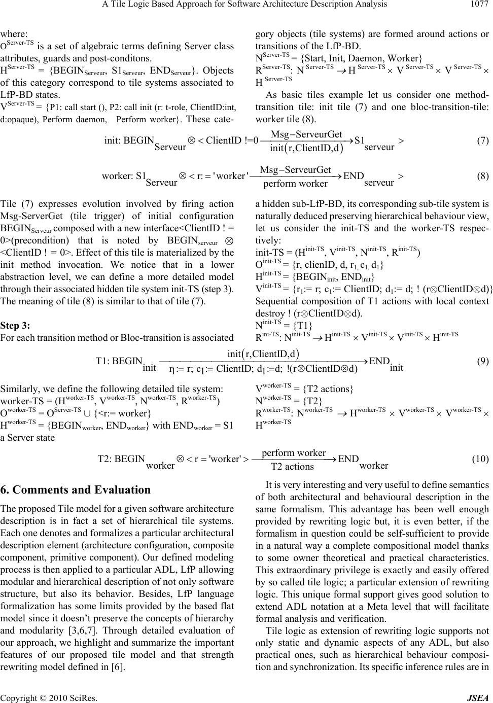 A Tile Logic Based Approach for Software Architecture Description Analysis 1077 where: OServer-TS is a set of algebraic terms defining Server class attributes, guards and post-conditons. HServer-TS = {BEGINServeur, S1Serveur, ENDServeur}. Objects category correspond to tile systems associated to r-TS = {P1: call start (), P2: call init (r: t-role, ClientID:int, d:opaque), Perform daemon, Perform worker}. These cate- gory objects (tile systems) are formed around actions or transitions of the LfP-BD. NServer-TS = {Start, Init, Daemon, Worker} RServer-TS: N Server-TS H Server-TS V Server-TS V Server-TS Server-TS tion tile: init tile (7) and one bloc-transition-tile: worker tile (8). of this LfP-BD states. VServe H As basic tiles example let us consider one method- transi Msg ServeurGet init: BEGINClientID !=0S1 Serveur serveur init r,ClientID,d (7) Msg ServeurGetENDserveur perform worker worker: S1r:'worke Serveur r ' (8) Tile (7) expresses evolution involved by firing action Msg-ServerGet (tile trigger) of initial configuration B a h d preserving hierarchical behaviour view, t us consider the init-TS and the worker-TS respec- (rÄClientIDÄd). Hinit-TS Vit-TS V H EGINServeur composed with a new interface<ClientID ! = 0>(precondition) that is noted by BEGINserveur Ä <ClientID ! = 0>. Effect of this tile is materialized by the init method invocation. We notice that in a lower abstraction level, we can define a more detailed model through their associated hidden tile system init-TS (step 3). The meaning of tile (8) is similar to that of tile (7). Step 3: For each transition method or Bloc-transition is associated idden sub-LfP-BD, its corresponding sub-tile system is naturally deduce le tively: init-TS = (Hinit-TS, Vinit-TS, Ninit-TS, Rinit-TS) Oinit-TS = {r, clienID, d, r1, c1, d1} Hinit-TS = {BEGINinit, ENDinit} Vinit-TS = {r1:= r; c1:= ClientID; d1:= d; ! (rÄClientIDÄd)} Sequential composition of T1 actions with local context destroy ! Ninit-TS = {T1} Rini-TS: Ninit-TS ininit-TS init-TS init T1: BEGINinit r: r; c: ClientI 11 Similarly, we define r ,C D; lientID,d E ND in d ) it d:d; !(rClientID 1 Vworker-TS = {T2 actions} Nworker-TS = {T2} (9) the following detailed tile system: w (10) Each one denotes and formalizes a particular architectural description element (architecture configuration, composite component, primitive component). Our defined modeling process is then applied to a particular ADL, LfP allowing modular and hierarchical description of not only software structure, but also its behavior. Besides, LfP language interesting and very useful to define semantics of riting logic but, it is even better, if the formalism in question could be self-s in a natural way a complete compos to some owner theoretical and practical characteristics. This extraordinary privilege is exactly and by so called tile logic; a particular e logic. This unique formal support gives good solution to ts not nly static and dynamic aspects of any ADL, but also ones, such as hierarchical behaviour composi- orker-TS = (Hworker-TS, Vworker-TS, Nworker-TS, Rworker-TS) Oworker-TS = OServer-TS È {<r:= worker} Hworker-TS = {BEGINworker, ENDworker} with ENDworker = S1 a Server state T2: BEGINr'worke worker 6. Comments and Evaluation The proposed Tile model for a given software architecture description is in fact a set of hierarchical tile systems. Rworker-TS: Nworker-TS Hworker-TS Vworker-TS Vworker-TS Hworker-TS perform workerEND r' worker T2 actions It is very formalization has some limits provided by the based flat model since it doesn’t preserve the concepts of hierarchy and modularity [3,6,7]. Through detailed evaluation of our approach, we highlight and summarize the important features of our proposed tile model and that strength rewriting model defined in [6]. extend ADL notation at a Meta level that will facilitate formal analysis and verification. both architectural and behavioural description in the same formalism. This advantage has been well enough provided by rew ufficient to provide itional model thanks easily offered xtension of rewriting Tile logic as extension of rewriting logic suppor o practical tion and synchronization. Its specific inference rules are in C opyright © 2010 SciRes. JSEA  A Tile Logic Based Approach for Software Architecture Description Analysis 1078 turn instantiated not freely as for rewriting logic, but in specific context and then composed implicitly to deduce further possible behaviours. For example, in the case of CS-tile model, the effect (call init (r, ClientID, d)) of init trigger of the system init-TS. During a computation, if init tile is executed, the system instan- tiates T1 automatically (rewriting synchronization rule) and then applies the horizontal tiles composition (init l e orm rker), e- hat compositional and hierarchical be- haviour semantics are really and naturally considered with a good rewriting synchronization; what is not so 2]. Our model also opens nfiguration. [1] D. Garlan and B. Schmerl, Modelling and Analysis,” Proc Australian Workshop on Safety Related Programmable . 69, 2006, pp.3-17. uccini and B. X. Li, “A Classification and ,” The f Sre, Vo 83, No. 5, May 2010, pp. 723-744. [3] D. Regep, “LfP: un langage de spécification pour supporter une démarche prototypage pour les systèmes ré oftware Architectures,” Computer Science, Vol. 4758, 2007, pp. tile (7), defined in Server-TS, will be the tile T1 (9), defined in the sub tile * T1) that involves T1 execution which creates its loca hcontext at the beginning and destroys it at the end. In t wo dsame way, worker tile (8) effect (perf riggetile fined in server-TS, trs the T2 (10) defined in the sub tile system worker-TS. Though these concrete exam- ples, we remark t evident in ordinary rewriting logic. 7. Conclusions The main contribution of this paper is to propose tile logic based modelling process of a system architectural description preserving the modularity and the hierarchy of initial specification, avoiding its flat form. We highlight the interest of our approach through LfP description language since it is equipped with rich notation allowing modular and hierarchical specification of software systems. Tile logic taking into account state changes with side effects and rewriting synchronization, has been proven as a high level (Meta) semantic framework, more appropriate to deal naturally with important ADL features that are more frequent, namely their structural and behavioural hierarchy as well as any components composition or synchronization. This particular advan- tage is due to the theoretical and practical characteristics of tile logic: categorical structures, guided rewriting via observations, flexible formats of configurations, tiles composition through interfaces, exploitation of three dimensional views (horizontal for structure, vertical for behaviour evolution and the third dimension for distri- bution). It is obvious that defining ADL semantics within a complete semantic framework facilitates formal executing and analyzing of software system specification. This work enforces and offers new possibilities for formal debugging, checking and executing the obtained tile logic model by mapping it into rewriting logic [18,19]. We note here that the executable specification to be obtained consequently, has the advantage to discard useless deductions thanks to guided rewritings in particular. Hence, our proposed model for LfP architecture description can provide an executable specification in Maude system [20] and its Université de Paris VI, 2003. [4] R. Bruni, “Tile logic for Synchronized Rewriting of Concurrent Systems,” PhD. Thesis, Computer Science Department, University of Pisa, Pisa, 1999. [5] J. Meseguer, “Conditional Rewriting Logic as a Unified Model of Concurrency,” Journal of Theoretical Computer Science, Vol. 96, No. 1, April 1992, pp. 73-155. [6] C. Jerad and K. Barkaoui, “On the Use of Rewriting Logic for Verification of Distributed Software Architecture Description Based LfP,” 16th IEEE International Workshop on Rapid System Prototyping (RSP'05), June 2005, pp. 202-208. [7] C. Jerad, K. Barkaoui and G. Touzi, “A. Hierarchical Verification in Maude of LfP S practical checking tools [21,2 way to several other perspectives such as semantics enrichment of LfP component behaviour under particular constraints such dynamic reco REFERENCES “Architecture-Driven eedings of the 11th Systems (SCS’06), Vol [2] P. Zhang, H. M Comparison of Model Checking Software Architecture Techniques Journal oystems and Softwal. de développement par partis,” thèse de doctorat, Lecture Notes in 156-170. [8] D. C. Lukham, “Rapide: A language Toolset for Simulation of Distributed System by Partial Ordering of Events,” DIMACS Workshop on Partial Order Methods in Verification (POMIV), July 25-26, 1996, pp. 329-358. http://pavg.stanford.edu/rapide/rapide-pubs.html [9] R. J. Allen, “Formal Approach to Software Architecture,” PhD. Thesis, University of Carnegie Mellon, Pittsburgh, May 1997. [10] C. Braga and A. Sztajnberg, “Towards a Rewriting Semantics for a Software Architecture Description Language,” Proceedings of the Brazilian Workshop on Formal Methods, Vol. 95, May 2004, pp. 149-168. [11] R. Bruni, J. Fiadeiro, I. Lanese, A. Lopes and U. Montanari, “New Insights into the Algebraic Properties of Architectural Connectors,” International Federation for Information Processing, Vol. 155, 2004, pp. 367-380. [12] R. Bruni, U. Montanari and U. Sassone, “Observational Congruences for Dynamically Reconfigurable Tile Systems,” Theoretical Computer Science, Vol. 335, No. 2-3, May 2005, pp. 331-372. [13] D. Hirsch and U. Montanari, “Consistent Transformations C opyright © 2010 SciRes. JSEA  A Tile Logic Based Approach for Software Architecture Description Analysis Copyright © 2010 SciRes. JSEA 1079 op on Distributed Systems, Vol. 28, 1999. [1 Tran- and U. Montanari, “Mapping Tile Logic into June 38, No. 3, June 2009, pp. for Software Architecture Styles of Distributed Systems,” Worksh 4] F. Arbab, R. Bruni, D. Clarke, I. Lanese and U. Montanari, “Tiles for Reo,” Lecture Notes in Computer Science, Vol. 5486, 2009, pp. 37-55 [15] A. Choutri, F. Belala and K. Barkaoui, “Towards a Tile Based LfP Semantics,” Second International Conference on Research Challenges in Information Science (RCIS 2008), June 2008, pp. 9-16. [16] C. Bouanaka, A. Choutri and F. Belala, “On Generating Tile System for Software Architecture: Case of a Colla- borative Application Session,” ICSOFT’07, Barcelone, 2007, pp. 123-126. [17] F. Gilliers, “Développement par prototypage et Génération de Code à partir de LfP, un langage de modélisation de haut niveau,” thèse de doctorat, Université P. & M. Curie, Paris, 2005. [18] R. Bruni, J. Meseguer and U. Montanari, “Tiling sactions in Rewriting Logic,” Electronic Notes in Theore- tical Computer Science, Vol. 71, April 2004, pp. 90-109. [19] J. Meseguer Rewriting Logic,” Lecture Notes in Computer Science, Vol. 1376, 1998, pp.62-91. [20] M. Clavel, F. Duran, E. Eker, S. N. Marti-Oliet, Lincoln, P. J. Meseguer and C. Talcott, “Maude 2.0 Manual,” 2003. http://maude.cs.uiuc.edu [21] S. Eker, J. Meseguer and A. Sridharanarayanan, “The Maude LTL Model Checker and Its Implementation,” Proceedings of the 10th International Conference on Model Checking Software, 2003, pp. 230-234. [22] R. Bruni, A. LIuch and U. Montanari, “Hierarchical Design Rewriting with Maude,” Electronic Notes Theore- tical Computer Science, Vol. 2 45-62. |