Modern Mechanical Engineering
Vol.2 No.3(2012), Article ID:22183,15 pages DOI:10.4236/mme.2012.23010
Performance Improvement of the LM Device and Its Application to Precise Measurement of Motion Trajectories within a Small Range with a Machining Centre
1Department of Mechanical Engineering, Faculty of Engineering, Kyushu Sangyo University, Fukuoka City, Japan
2Department of Computer Science and Technology, University of Bedfordshire, Luton, UK
3State Key Laboratory of Mechanical Transmission, Chongqing University, Chongqing, China
4Advanced Manufacturing and Enterprise Engineering Department, School of Engineering and Design, Brunel University, Uxbridge, UK
5Product Design and Engineering Department, School of Engineering and Information Sciences, Middlesex University, London, UK
Email: *yong.yue@beds.ac.uk
Received March 21, 2012; revised April 27, 2012; accepted May 10, 2012
Keywords: Motion Accuracy; Measurement Device; Performance Improvement; Small Size Motion; Machining Centre
ABSTRACT
In order to apply the LM device previously developed to precisely measuring small motion trajectories located on the different motion planes, three major improvements are successfully performed under the condition of completely maintaining the advantages of the device. These improvements include 1) development of a novel connection mechanism to smoothly attach the device to the spindle of a machining centre; 2) employment of a new data sampling method to achieve a high sampling frequency independent of the operating system of the control computer; and 3) proposal of a set-up method to conveniently install the device on the test machining centre with respect to different motion planes. Practical measurement experiment results with the improved device on a machining centre sufficiently demonstrate the effectiveness of the improvements and confirm several features including a very good response to small displacement close to the resolution of the device, high precision, repeatability and reliance. Moreover, based on the measurement results for a number of trajectories for a wide range of motion conditions, the error characteristics of small size motions are systematically discussed and the effect of the movement size and feed rate on the motion accuracy is verified for the machining centre tested.
1. Introduction
In recent years, with the advances of CNC machining technologies, especially in die manufacturing, more and more attention has been attracted from researchers and engineers on how to precisely detect and correctly evaluate the motion accuracy of Machining Centres (MCs) within a small area [1-10]. Several specific measuring devices have been developed for this purpose. For example, Kwon and Burdekin [1,2] developed a measuring device, which consists of a precision cube and two displacement sensors, to detect and evaluate the motion trajectories of both circular and linear interpolation motion within a small range for a MC. Kakino et al. [3] applied a cross grid encoder to measure small motion trajectories with a precision MC. Schmitz and Ziegert [4] produced an instrument combining three laser ball bars to evaluate the spatial CNC contouring accuracy within a relatively small area although the instrument needs a large installation space. Lee et al. [9] presented a measurement system, which included a fixture to mount multiple sensors and a target as the detecting object, to measure geometric errors of a miniaturized machine tool and further attempted to compensate these errors through a software-based method. Kono et al. [10] developed a device combining an optical flat and a laser displacement sensor to measure the geometric errors, associated with the feedback signal utilization of the servo axis from the control apparatus, and then successfully compensated the time-dependent components of these errors for a high-precision machine tool. However, problems exist to some extent in the practical applications of these devices, for example, the expensive price, the complex and time-consuming set-up process of the device on a machine tool, the orientation limitation to the motion planes or motion direction to be measured, and the limited application to specific objects. Nowadays, the most popular devices for detecting and evaluating MC motion accuracy are the double ball bar (DBB) [11] and the cross grid encoder whose commercial product is called as KGB [12]. Based on the principle and structure, a traditional DBB is unsuitable for measuring the motion trajectories within a small area. As an expensive device, the KGB can test a general motion trajectory located on a plane perpendicular to the MC spindle with a fairly high accuracy [13]; however, for a motion trajectory located on other planes, the operation to set up the device on a tested MC is not only difficult and time-consuming but also requires some specific apparatus and jig to ensure the alignment precision between the optical head and encoder [14]. Therefore, the problem of precisely assessing the accuracy in a small size motion has not yet been satisfactorily resolved, and there have been few publications of systematic research on the error characteristics and causes of the trajectory in small size MC motions.
The authors have successfully developed a device called the LM device, with a basic structure consisting of a double-bar linkage mechanism and two laser rotary encoders, for measuring motion accuracy of a MC with a vertical spindle previously [15,16]. The device is applicable to measuring the trajectory of a general planar motion located on a plane perpendicular to the MC spindle. The device has a simple and compact structure and yet provides a large working range with a high resolution. The cost to produce the device is fairly low. Both the installation process on the MC and the measurement operation are simple and convenient in practical applications. The LM device is able to measure small size motion trajectories of the MC; however, based on the mechanical structure feature and data acquisition method, some limitations in measuring performance exist to trajectories in a small area, especially when the motion is fed at a high speed.
This paper presents further developments and improvements for applying the LM device to precisely measuring small size motion trajectories located on different planes. Moreover, as a practical application of the device, a case study, in which the accuracy of a small size motion is detected and evaluated for the MC texted, has been performed. Section 2 describes the improvements performed, including an original connection mechanism, a new data sampling method and a set-up method to install the device on the MC with respect to different motion planes. Section 3 presents and discusses in detail the experiment results with the improved device for the measurement of small size circular and linear interpolation motion trajectories which are located on the X-Y, Y-Z and X-Z planes of the MC respectively. The experiment results sufficiently demonstrate the effectiveness of the improvements. At the same time, based on the measurement results for a number of motion trajectories performed under a wide range of motion conditions, the error characteristics and related causes are verified for the small size motion with the MC. Section 4 draws conclusions on the work presented.
2. Improvements of Measurement Device
Figure 1 shows a schematic diagram of the LM device consisting of a double-bar linkage and two laser rotary encoders which are set at the root end on Link 1 and Link 2 to detect the rotation angles of the links. The device base is fixed on the table of the MC with a vertical spindle. The tip of Link 2 is attached to the spindle with a connection mechanism. The rotation planes of both links are parallel to each other and perpendicular to the rotation axis of the spindle.
Before starting the measurement, a measuring coordinate frame can be set up through a simple operation [15]. The X, Y and Z axes are parallel to those of the MC respectively, and the Z axis coincides with the rotation axis on the root side of Link 1. Therefore, in the coordinate frame, the coordinates (X, Y, Z) of a measured point, which is defined as the intersection point between the spindle rotation axis and the X-Y plane, is given by the following equation:


Figure 1. Schematic diagram of the LM device.

where L1 and L2 are the link lengths, which is 100 mm in the LM device, and q1 is the rotation angle of Link 1 relative to the positive direction of the X axis and q2 is the rotation angle of Link 2 relative to Link 1. The resolution for both q1 and q2 is 1 second due to the used laser rotary encoders, Canon K-1, and interpolators, Canon IU-16. The entire working range of the LM device is located on the X-Y plane and has a disc shape around the origin O whose inner radius is 10 mm and outer radius is 190 mm. The LM device has the position resolution of less than 0.5 mm at the radial direction and less than 1 mm at the argument direction for any measured point within the working range [15].
In order to precisely measure the motion trajectory in a small area with a high feed rate, three major improvements have been performed on the previous device. One is to develop a novel connection mechanism attaching the tip of Link 2 to the MC spindle. The other is to employ a new data acquisition method. The third is to design a simple set-up jig that enables the device to measure trajectories located on different motion planes.
2.1. The New Connection Mechanism
In the previous device, a conventional coupler was used to connect the tip of Link 2 and the MC spindle to be measured. Some potential errors such as the flatness error on the table surface of the MC or the assembly errors of the device itself may lead to the movement of the tip of Link 2 along the Z direction in the measurement. Such movement is forcedly absorbed by the coupler and hardly affects the measuring results for a trajectory in a large size motion or in a small size motion but with a low feed rate. However, the movement may have some negative effect on the rotation of links and result in undesired errors in the measuring results for a small size motion with a high feed rate.
In order to solve this problem, a novel connection mechanism as shown in Figure 2 has been developed. A precision steel ball is fixed at the tip of a stroke ball bearing pin and the stroke bearing is assembled on Link 2. The clearance of the stroke bearing is carefully adjusted at 0 by the manufacture. The pin can freely rotate around the axis and slide along the axial direction. A stopping ring mounted at the bottom of the pin limits the sliding displacement within 3 mm. A connecting bar, at whose tip a magnet piece is fixed, is attached to the MC spindle. During the measurement, the ball is connected to the magnet piece via a supporter consisting of three small precision balls. Because the magnetic force in the connection

Figure 2. Connection mechanism between the improved device and the spindle of MC.
is considerably larger than the friction in the stroke bearing, no relative sliding happens between the steel ball and the supporting balls in the measurement. By applying the mechanism, not only a very small relative displacement between the device and the spindle can be smoothly achieved but also the influence of the movement of Link 2 tip along the Z direction can be naturally absorbed. Furthermore, the set-up operation of the improved device on the MC becomes simpler and easier than the previous device.
2.2. The Data Sampling Method
The software of the previous device was constructed on the MS-DOS platform. The sampling command was sent one by one from a personal computer to the counter board at each sampling time. With this method, it is very difficult to ensure a sampling period in the ms order under the WINDOWS environment. As an effective solution to this problem, a high-speed counter board, Contec CNT32-8M (PCI), is employed in the improved device. Through the utilization of a sampling function based on the board’s clock, a sampling period of 50 ms, which is independent of the operating system of the personal computer, is achieved.
2.3. The Set-Up Method of the LM Device on the MC to Measure Trajectories Located on Different Motion Planes
As explained above, the LM device was developed for measuring the motion trajectory on a parallel plane to the standard surface of the device, i.e. the table surface of the MC to be tested. To detect trajectories on other motion planes, for example, a vertical plane for a MC with vertical spindle, a suitable standard to set-up the device on the MC is necessary. For this purpose, a simple jig is designed, as shown in Figure 3. The jig consists of two main parts: a rectangular part with a right angle and a block with good parallelism between the upper face and

Figure 3. Setting up the LM device on the table of MC.
bottom face. The rectangular part is placed on the upper face of the block to provide a standard surface to set the device. Thus, once the device is fixed on the setting plane of the rectangular part, the rotation planes of Link 1 and Link 2, and then the motion plane, where a trajectory to be measured is located on, are restricted to be parallel to the setting plane. Moreover, in order to prevent the collision between the device and spindle in the measurement, the connection mechanism is attached to the spindle through an inclined bar fixed on the spindle.
It should be noticed that strict parallelism accuracy between the setting plane and motion plane is not required because of the feature of the connection mechanism, i.e. if a small parallelism error exists, the effect is smoothly absorbed by the mechanism. From the results of the measurement experiments, it has been verified with the improved device that limiting the parallelism precision within 50 mm/100 mm is sufficient to ensure the measuring accuracy of motion trajectory in practical applications.
In addition, if a part available to freely adjust the angle of the setting plane is built in the jig instead of the rectangular part, the motion trajectory on a general plane can be readily measured by the LM device. In such situation, based on the same reason presented above, a strict setting accuracy for the setting plane relative to the motion plane is not required.
3. Results and Discussions of Measurement Experiments
In order to verify the effectiveness of the improvements, measurements of small size motion trajectories are performed on the MC with the improved LM device under a wide range of motion conditions. Furthermore, in order to examine the reliability of the measured results, following the ISO standard, ISO 230-1:1996 [17], the measured trajectories are compared with the profile of the work pieces machined under the same motion conditions. Based on the measured results of the motion trajectories, the error characteristics of small size motions are discussed and their causes verified with the tested MC. Because a cutter path for machining a complex contour is usually generated through an interpolation operation of circular arcs or linear segments in industrial practices, the trajectories to be measured are restricted to a circular or linear interpolation motion in this research.
A vertical-spindle MC with a control system of semiclosed loop, Wasino WMC-4, is tested. The movable range of the MC is 900 mm in the X direction, 450 mm in the Y direction and 510 mm in the Z direction, respectively. The NC system is FANUC Series 0-MC, the number of simultaneously controllable axis is 2.5 and the minimum input increment is 1 mm. The basic structure of the MC consists of a Z axis column and a XY table with a hydraulic slideway, where the X table is ridden on the Y table. The maximum feed rate of cutting is 5000 mm/min. In the experiments, the origin of the measuring coordinate frame is set at the central position of the movable range of the MC.
3.1. Circular Motion Trajectories on the X-Y Plane
The experiment conditions are presented in Table 1. The centre of circular motions to be measured is set at point (100, 0) in the measuring coordinate frame as shown in Figure 4. For every condition, the trajectories with respect to a single revolution and to three consecutive revolutions in both clockwise (CW) and counter clockwise (CCW) directions are measured and recorded, respectively. The number of measured points along a full circle trajectory is 800 ~ 2000. The trajectory errors are illustrated in the form of roundness deviation calculated by the least squares criterion in the following if no notation is given.
Figure 5 shows the measured results for the circular motion with a radius of 1 mm and feed rate of 1000 mm/min, where the trajectory in (a) corresponds to the

Figure 4. Patterns of measured motion trajectories on the X-Y plane.

Figure 5. Measurement examples of circular motion under the condition of R = 1 mm and F = 1000 mm/min on the X-Y plane.
single revolution motion, the trajectory in (c) is for the three consecutive revolutions motion and (b) shows the part of the two central revolutions extracted from (c). The arrows indicate the feed direction. As shown in the figure, within a transient process of the feed motion state from stop to stable or vice versa, the radius changes due to the actual feed speed, i.e. the lower the actual feed speed is, the larger the radius value is. While the trajectories in the two central revolutions, i.e. corresponding to the stable state of the feed motion, coincide well with each other. Furthermore, if both trajectory parts of the first and last half circle in (c) are connected, the curve shape perfectly agrees with that of the trajectory in (a). The same trend is also observed from the measured results for other motion conditions. Therefore, it can be concluded that the measured results with the improved LM device not only offer a good accuracy but also a good repeatability.
Figure 6 shows the results of three consecutive revolutions with a radius of 2 mm. Similar to those shown in Figure 5, the trajectories of the two central revolutions demonstrate good stability. The faster the specified feed rate is, the larger the radius change is so that the roundness deviation of the entire trajectory becomes more remarkable. By numerically differentiating the trajectory data with respect to the sampling time used in the measurement, the X and Y components of the actual feed speed can be estimated [18]. Figure 7 illustrates the feed speed components obtained from the trajectories in the CW direction in Figure 6. With the increase of the specified feed rate, the actual feed speed becomes less than the specified and the actual motion time becomes somewhat longer than the normal time, especially, in the areas close to the start and end points. As a result, the least square radius of circular motion, Rm, calculated from the trajectory of two central revolutions, decreases as the specified feed rate increases. As well known, the delay elements in the driving system of the MC results in the decrease in the radius of the circular motion [19].
Figure 8 shows the results of three consecutive revolutions motion with a radius of 0.02 mm. There are some undulations looking like saw-teeth with a height of about 1 mm in these trajectories. The phenomenon is caused by the measuring resolution of the device. It is also observed that the start point does not coincide with the end point in position. This can be attributed to the effect of the backlash in the driving system of the MC. Comparing Figure 8 with Figure 6, a similar trend can be observed, i.e. the roundness deviation of trajectory goes up with the increase of the feed rate, as well as other measuring conditions. However, since the motion size itself is very small in this situation, the curve of roundness deviation looks like a lozenge rather than a circle even at a comparatively low feed. Figure 9" target="_self"> Figure 9 illustrates the motion trajectory directly measured corresponding to a feed rate of 20 mm/min. Except for an area near the start or end point, the trajectory almost becomes a regular square. Figure 10 shows the estimated feed speed components from the trajectory data in the CW direction in Figure 8. These results demonstrate that with the increase of the specified feed rate, the movement between the X and Y axes goes out of the circular interpolation rule gradually, at the end,

Figure 6. Measured results of the circular motion trajectories with a radius of 2 mm on the X-Y plane.


Figure 8. Measured results of the circular motion trajectories with a radius of 0.02 mm on the X-Y plane.

Figure 9. Directly obtained motion trajectories on the X-Y plane under the conditions of R = 0.02 mm and F = 20 mm/min.

Figure 10. Estimated feed speed from the displacement data of CW rotation in Figure 8.
the movements of both axes are entirely separated into the independent movement of each axis and individually performed in turn. Actually, the MC table itself fails in motion when a higher feed rate such as 50 mm/min is specified, as shown in Figure 11. In this situation, the Y axis of the MC seems to hardly move. The uncompleted motion of the table is also observed in other circular motions with a radius of less than 0.1 mm if the specified feed rate exceeded a corresponding critical value, as summarized in Table 1. So far, there has been no publication reporting this phenomenon which may be caused by the lack of the servo capability with the MC drive system due to an excessive feed rate with respect to the motion size.
3.2. Linear Interpolation Motion Trajectories on the X-Y Plane
The experiment conditions are shown in Table 2. The centre of linear interpolation motion is set at point (100, 0) in the measuring coordinate frame and the trajectory is illustrated in Figure 4. In the NC program to drive the MC table, no dwell action is specified at the connection between two linear segments. Under each condition, the trajectories of three consecutive loops in both the CW and CCW directions are measured and recorded. The

Table 1. Measuring conditions for circular motion on the X-Y plane.

Table 2. Measuring conditions for linear interpolation motion on the X-Y plane.
number of measured points along a full square trajectory is 1000 - 2000. In the following discussions, the measured results are directly illustrated in a form of trajectory but the origin is replaced at point (100, 0).
Figure 12 illustrates the results of the motions with a side length of 1 mm. With the increase of feed rate, the corner shape shifts from a right-angle to an arc and the length of the side becomes shorter than the specified value. Figure 13 illustrates the estimated feed speed components from the trajectory data in the CW direction. As the specified feed rate increases, the actual feed speed becomes less than the specified and the curves of the  and
and  components shift from an ideal form of rectangles which just half overlap each other to a triangular form. The phenomenon is caused by the NC acceleration/deceleration motion around a point connecting two linear segments as pointed out by Shih et al. [20] in their theoretic analysis.
Figure 14 illustrates the results of the motion with a side length of 0.04 mm. In the figure, not only the similar trend to Figure 12 but also a significant change of the side direction in trajectory, i.e. the inclination of a side drifts from 45˚ to 0˚ relative to the coordinate axes of the MC, can be observed. This means that the movement between the X and Y axes is almost entirely separated from the linear interpolation rule and individually

Figure 11.Continuous three rotation trajectories on the X-Y plane under the conditions of R = 0.02 mm and F = 50 mm/min.

Figure 12. Measured results of the linear interpolation trajectories with a side length of 1 mm on the X-Y plane.


Figure 14. Measured results of the linear interpolation motion trajectories with a side length of 0.04 mm on the X-Y plane.
performed in turn, just the same as the situation of the circular motion in Figure 8. In addition to the results obtained from other motion conditions, the results of the feed speed obtained by a numerical differentiation operation also give a good support to this conclusion. As stated previously, there has been no report on such motion trajectory errors and Shih’s theory [20] cannot provide an appropriate interpretation of such phenomenon. If a higher feed rate such as 100 mm/min is specified, the table of the MC itself fails in the motion. Actually, as shown in Table 2, the uncompleted motion of the MC table is observed due to some linear interpolation motion with a side length of less than 0.1 mm.
3.3. Motion Trajectories Located on Vertical Planes
The motion to be detected is limited to the X-Z and Y-Z planes due to the capability of the MC. The experiment conditions are shown in Table 3 and the motion trajectories in Figure 15. Under each condition, both circular and linear interpolation motions are tested, and the trajectory is located at four positions on each plane and measured in both CW and CCW directions for three consecutive rotations. No dwell action is specified between every two linear segments in the NC program. The number of measured points along a full rotation trajectory is 1500. The trajectories shown below are tested in Posture I of the device linkage as defined in Figure 15 if no notation is given.

Table 3. Measuring conditions for motion trajectories on the X-Z and Y-Z planes.
Figures 16 and 17 respectively show the results to a circular motion located on the X-Z plane with a radius of 1 mm and a linear interpolation motion located on the Y-Z plane with a side length of 1 mm. Figure 18 illustrates the estimated components of the feed speed from the trajectory data in the CCW direction in Figure 16. By comparing these results with those of the X-Y plane presented above, it can be observed that the trajectories have similar features although they are positioned on different planes. That is, with the increase of the specified feed rate, the radius of circular motion or the side length of linear interpolation decreases, the actual feed speed components become less than the specified. As a result, the movement between the two driving axes tends to lose the interpolation rule. The phenomenon is also confirmed from the results corresponding to other positions and motion conditions.
Figure 19 shows the measured results of the circular motions at different central positions on the Y-Z plane, which have a radius of 2 mm and are performed at a feed rate of 500 mm/min. Some differences among these figures due to different central positions can be observed. In order to verify whether the posture change of the device linkage in the measurement affects the measured results, tests with the same conditions and central positions are carried out but the link posture is set in Posture II defined in Figure 15. The gravity distribution of the linkage is rather different between Posture I and Posture II, as shown in Figure 15. For this reason, the influence of the posture change on the measurement should be reflected in the measurement results due to either Posture I or Posture II, for example, in a form of the differences in the radius value and curve shape. Figure 20 provides a comparison between Posture I and Posture II. Both trajectories at the same position and feed rate from Posture I and Posture II agree well with each other for the radius and shape. For other conditions of circular motions as well as linear interpolation motions, similar results are also confirmed. This demonstrates that the gravity distribution difference from the posture change of the device linkages has almost no effect on the measurement results. Therefore, the differences among the motion trajectories due to different positions in Figure 19 can be attributed to the motion errors of the MC itself [19], and thus it can be concluded that the measured results by the improved device are sufficiently reliable even for trajectories located on vertical motion planes.
3.4. Comparison of the Motion Trajectories with Profiles of Machined Workpiece
As a further verification of the reliability of the measured results, following the ISO standard [17], a comparison of the motion trajectory with the profile of the machined workpiece is carried out. The machined features of the workpiece are a circular shaft with a diameter of 7 mm and a rectangular hole consisting of four straight sides of 5 mm and four round corners with a radius of 1.5 mm. During the machining, the workpiece is fixed on the MC spindle which does not rotate and an independently driven high-speed spindle is horizontally set on the MC table, as shown in Figure 21. Through feeding the table, the cutter,

Figure 15. Positions of the measured motion trajectories on the X-Z and Y-Z planes.
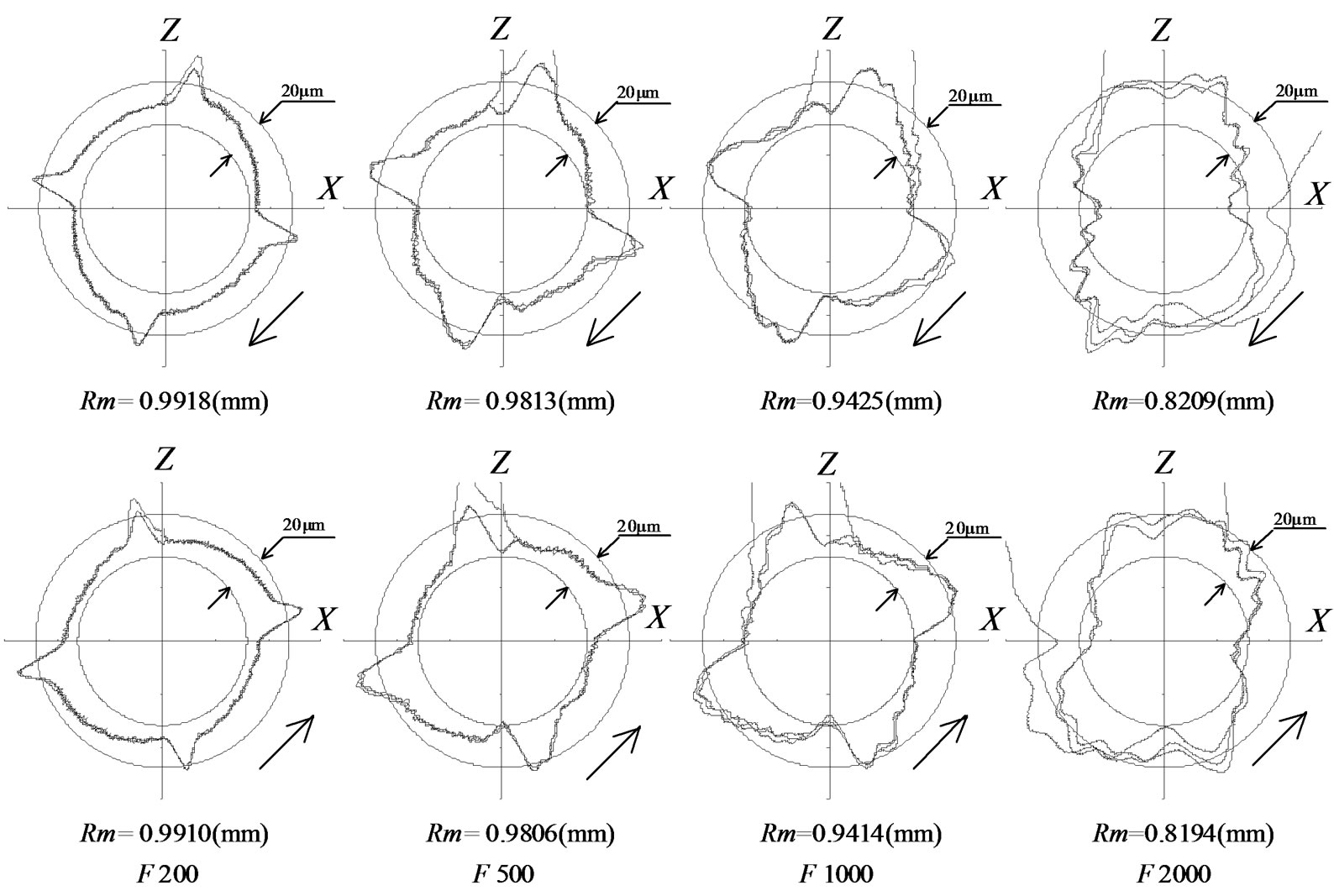
Figure 16. Measured results of the circular motion with a radius of 1 mm located at the central position of (0, -100) on the X-Z plane.

Figure 17. Measured results of the linear interpolation trajectories with a side length of 1 mm located at the central position of (100, 0) on the X-Z plane.


Figure 19. Measured results of the circular motion trajectories with a radius of 2 mm and a feed rate of 500 mm/min located at different central positions on the Y-Z plane.

Figure 20. Comparison of measured circular motion trajectories due to the different linkage posture of the device (on the Y-Z plane with R = 2 mm and F = 500 mm/min).

Figure 21. Setting-up in the machining of workpiece.
a square end mill with a diameter of 3 mm, performs the feature cutting. The feed motion trajectories of the cutter are a circular motion with a radius of 5 mm for the circular shaft and a rectangular motion with a side length of 5 mm for the rectangular hole, respectively. In machining each feature, the cutter is fed for two full revolutions. The cutting conditions are summarized in Table 4. The circular shaft profiles are measured by a roundness measuring machine, Mitsutoyo RA-400, whose probe has a sphere stylus of 1.6 mm diameter, in non-filtering mode. The rectangular hole profiles are measured by a coordinate measuring machine, Mitsutoyo BHN506, to which a probe of sphere stylus with a diameter of 2 mm is attached. The number of measured points along a full contour is 1800. The motion trajectories with respect to three consecutive revolutions are measured and the number of measured points along a full revolution is 3000 for both circular and rectangular motions.
Figure 22 illustrates a comparison between the roundness of the circular shaft and the circular motion trajectory located on the Y-Z plane. Because of the influence of the radius of the cutter and probe stylus, the step noncontinuity of the roundness in the shaft profiles looks slightly smaller than that of the motion trajectories. Except for this difference, the two results match each other very well.
Figure 23 illustrates a comparison of the profile of the rectangular hole with the rectangular motion trajectory located on the X-Z plane. As the offset curves of the cutter motion, the profile of each rectangular hole matches well the corresponding motion trajectory, which consists of the first half and the last half revolution.
For the other motion conditions, the same results are also confirmed. Because of the stipulation of the ISO 230-1:1996 and the high accuracy of the roundness measuring machine and the coordinate measuring machine for form measurement of feature, the measurement results of both machined features of the workpiece can be considered equivalent to the motion trajectories [17]. Therefore, it can be concluded that the measurement results with the improved device are sufficiently accurate and reliable.
4. Conclusions
The following conclusions can be drawn based on the experiment results and discussions:
1) In order to improve the performance for measuring small size motion trajectories of a MC with a high feed rate, effective improvements have been performed on the LM device while maintaining the advantages of the device. Experimental results with the improved device, especially comparing the measured motion trajectories with the profiles of the machined workpiece, have sufficiently confirmed the features of very good response to small displacements close to the device resolution, high precision, repeatability and reliability.
2) The proposed set-up method is very effective and efficient for measuring motion trajectories located on the vertical planes. Little influence from the gravity distribution due to different linkage postures of the device has been observed in the measurement results.
3) Based on the measurement results for a number of trajectories under a wide range of motion conditions, it has been systematically verified that the motion accuracy of the MC tested rapidly deteriorates with the decrease of the movement size and the increase of the feed rate

Figure 22. Comparison of the profiles of circular shaft with the circular motion trajectories.

Figure 23. Comparison of the profiles of rectangular hole with the circular motion trajectories.

Table 4. Machining conditions for the circular axis and rectangular hole.
specified by the NC program in both circular arc and linear segment interpolation motions. This is due to the lack of the servo capacity of the MC for the interpolation motion within a small area. When an excessive feed rate with respect to the motion size is specified, the movement between related servo axes goes out of the required interpolation rule, and furthermore the movement is separated into the independent movement of each axis which is individually performed in turn.
As a result, it can be concluded that the improvement with the LM device is very successful for the purpose. Moreover, the outcomes obtained from the case study on the trajectory error characteristics of small size motions provide a systematic basis for further research on the contouring manufacture accuracy with machining centres.
REFERENCES
- H. D. Kwon and M. Burdekin, “Development and Application of a System for Evaluating the Feed-Drive Errors on Computer Numerically Controlled Machine Tools,” Precision Engineering, Vol. 19, No. 2, 1996, pp. 133- 140.
- H. D. Kwon and M. Burdekin, “Adjustment of CNC Machine Tool Controller Setting Values by an Experimental Method,” International Journal of Machine Tools & Manufacture, Vol. 38, No. 9, 1998, pp. 1045-1065. doi:10.1016/S0890-6955(97)00058-8
- Y. Kakino, Y. Ihara, S. Lin, S. Hayama, K. Kawakami and M. Hamamura, “Measurement of Motion Accuracy and Improvement of Machining Accuracy on Ultra-High Precision NC Machine Tools by Using Cross Grid Encoder Test,” Journal of the Japan Society for Precision Engineering, Vol. 62, No. 11, 1996, pp. 1612-1616. doi:10.2493/jjspe.62.1612
- T. Schmitz and J. Ziegert, “Dynamic Evaluation of Spatial CNC Contouring Accuracy,” Precision Engineering, Vol. 24, No. 2, 2000, pp. 99-118. doi:10.1016/S0141-6359(99)00034-3
- X. Mei, M. Tsutsumi, T. Yamazaki and N. Sun, “Study of the Friction Error for a High-Speed High Precision Table,” International Journal of Machine Tools & Manufacture, Vol. 41, No. 10, 2001, pp. 1405-1415. doi:10.1016/S0890-6955(01)00025-6
- X. Mei, M. Tsutsumi, T. Tao and N. Sun, “Study on the Compensation of Error by Stick-Slip for High-Precision Table,” International Journal of Machine Tools & Manufacture, Vol. 44, No. 6, 2004, pp. 503-510. doi:10.1016/j.ijmachtools.2003.10.027
- Y. Suzuki, A. Matsubara and Y. Kakino, “A Study on Improvement of Contouring Accuracy in Small Circular Motion for NC Machine Tools—Improvement of Accuracy by Altering the Feed Rate Limitation Method,” Journal of the Japan Society for Precision Engineering, Vol. 70, No. 6, 2004, pp. 1266-1270. doi:10.2493/jjspe.70.746
- K. Iwasawa, A. Iwama and K. Mitsui, “Development of a Measuring Method for Several Types of Programmed Tool Paths for NC Machine Tools Using a Laser Displacement Interferometer and a Rotary Encoder,” Precision Engineering, Vol. 28, No. 4, 2004, pp. 399-408. doi:10.1016/j.precisioneng.2004.01.004
- J. H. Lee, Y. Liu and S.-H. Yang, “Accuracy Improvement of Miniaturized Machine Tool: Geometric Error Modelling and Compensation,” International Journal of Machine Tools & Manufacture, Vol. 46, No. 12-13, 2006, pp. 1508-1516. doi:10.1016/j.ijmachtools.2005.09.004
- D. Kono, A. Matsubara, I. Yamaji and T. Fujita, “HighPrecision Machining by Measurement and Compensation of Motion Error,” International Journal of Machine Tools & Manufacture, Vol. 48, No. 10, 2008, pp. 1103-1110. doi:10.1016/j.ijmachtools.2008.02.005
- S. H. H. Zargarbashi and J. R. R. Mayer, “A Model Based Method for Centring Double Ball Bar Test Results Preventing Fictitious Ovalization Effects,” International Journal of Machine Tools & Manufacture, Vol. 45, No. 10, 2005, pp. 1132-1139. doi:10.1016/j.ijmachtools.2005.01.003
- http://www.heidenhain.co.de/
- S. Ibaraki, W. Goto, A. Matsubara, T. Ochi and M. Hamamura, “Self-Calibration of a Cross Grid Encoder,” Journal of the Japan Society of Precision Engineering, Vol. 72, No. 8, 2006, pp. 1032-1037.
- A. Du, S. Zhang and M. Hong, “Development of a Multi-Step Measuring Method for Motion Accuracy of NC Machine Tools Based on Cross Grid Encoder,” International Journal of Machine Tools & Manufacture, Vol. 50, No. 3, 2010, pp. 270-280. doi:10.1016/j.ijmachtools.2009.11.010
- H. Qiu, Y. Li and Y.-B. Li, “A New Method and Device for Motion Accuracy Measurement of NC Machine Tools, Part 1: Principle and Equipment,” International Journal of Machine Tools & Manufacture, Vol. 41, No. 4, 2001, pp. 521-534. doi:10.1016/S0890-6955(00)00092-4
- H. Qiu, Y.-B. Li and Y. Li, “A New Method and Device for Motion Accuracy Measurement of NC Machine Tools, Part 2: Device Error Identification and Trajectory Measurement of General Planar Motions,” International Journal of Machine Tools & Manufacture, Vol. 41, No. 4, 2001, pp. 535-554. doi:10.1016/S0890-6955(00)00093-6
- ISO 230-1, “Test Code for Machine Tools—Part 1: Geometric Accuracy of Machines Operating under No-Load or Finishing Conditions,” 1996.
- H. Qiu, “Velocity Measurement for Planar Motions of Machines Using the LM Measuring Device,” Journal of Robotics and Mechatronics, Vol. 10, No. 4, 1998, pp. 358-363.
- Y. Kakino, Y. Ihara, N. Y. akatsu, M. Yonetani and T. Teshima, “A Study on the Motion Accuracy of NC Machine Tools (4th Report)—Compensating for Decreasing Error of the Circle Radius during Circular Interpolation Motion,” Journal of the Japan Society for Precision Engineering, Vol. 54, No. 6, 1988, pp. 1113-1118. doi:10.2493/jjspe.54.1113
- Y.-T. Shih, C.-S. Chen and A.-C. Lee, “Path Planning for CNC Contouring around a Corner,” JSME International Journal, Series C, Vol. 47, No. 1, 2004, pp. 412-420. doi:10.1299/jsmec.47.412
NOTES
*Corresponding author.