Open Journal of Civil Engineering
Vol.2 No.1(2012), Article ID:17806,9 pages DOI:10.4236/ojce.2012.21001
Prediction of Nonlinear Cyclic Behaviors of Shear Wall Composed of Acacia mangium Framing and Fiber Cement Board Sheathing
Laboratory of Structural Function, Kyoto University, Kyoto, Japan
Email: maryokohadi@gmail.com
Received December 10, 2011; revised January 15, 2012; accepted January 22, 2012
Keywords: Earthquake-Resistant House; Shear Wall; Akasia Wood; FCB
ABSTRACT
The alternative types of composite structure made of wood and cement based building materials needs to meet with the high demand for earthquake-resistant houses in Indonesia. In order to understand the mechanism of earthquake resisting performance of shear wall, it is necessary to investigate not only elastic behavior of shear walls but also non-linear one. In this study, series of full-scale experiments on timber frame shear walls composed of Akasia wood (Acacia mangium) sheathed by Fiber Cement Board (FCB) were carried out. For predicting skeleton curve, a series of theoretical equations was derived, which cannot only solve arbitrary nail pattern shear wall but also nonlinear behavior after yielding. Further, for describing hysteresis loops of shear walls, so-called Normalized Cyclic Loop (NCL) model was adopted. By combining two theoretical approaches, weintended to predict whole cyclic shear wall behaviors tested. Good agreements were obtained from comparison between experiment and prediction. The information obtain by this study will be useful for practical engineers or structural designers to design the high performance earthquake resisting timber houses.
1. Introduction
From recent damage due to earthquakes in various places in Indonesia, it appears that residential houses made of concrete and/or masonry was insufficient and collapsed in severe earthquakes. More than fifteen years ago in Kobe, Japan, there was also a severe earthquake and devastating damage was observed on many timber houses. Since then, not only the Japanese government but also universities, institutes and commercial companies have been paying effort to make timber residential houses stiffer, stronger and tougher. Following this good previous example, an attempt was initiated in Indonesia to make residential houses more capable of surviving severe earthquakes in the future.
This paper aimed for establishing reliable shear walls by using Akasia wood frame, sheathed with Fiber Cement Board (FCB), which is similar to those being used for earthquake-resisting house in Indonesia.
In order to understand the mechanism of earthquake resisting performance of shear wall, we need to investigate non-linear behaviors of shear walls. For this end, the new theoretical equations derived, which can not only solve arbitrary nail pattern shear wall but also nonlinear behavior after yielding for obtaining skeleton curve. In addition to this, the Normalized Cyclic Loop (NCL) models for predicting hysteresis loops were used. And by combining these two theoretical approaches, intended to predict whole non-linear cyclic behaviors of shear walls, which were composed of Akasia wood frame and nail on FCB sheathing.
2. Material and Methods
2.1. Framing Materials
The Indonesian Akasia wood (Acacia mangium) of 40 × 80 × 3000 mm solid timber was used for all of framing member material shown in Figure 1, whose mechanical and physical properties are shown in Table 1.
The Spruce glulam beam of 120 × 120 mm cross-section was used for loading girder.

Figure 1. Akasia wood used as shear wall frames member.

Table 1. Akasia’s wood mechanical and physical of material property.
2.2. Sheathing Materials
The Sheathing material is Fiber Cement Board (FCB), in which Silica (35% by weight), calcium (35% by weight), pulp and wooden fiber (15% by weight) and others (15% by weight) produced by the Japanese commercial company with size of 1800 × 900 × 12 mm shown in Figure 2. The material properties of FCB are given in Table 2.
2.3. Fasteners
Two kinds of nails were used and their specification is shown in Table 3.
The N100 nails, which were used for fastener connection between frame member and the N75 used as fastener of FCB that were attached to the frame member shown in Figure 3.
2.4. Shear Wall Specimen
Two types of specimen were prepared as shown in Figures 4 and 5. Test specimens named, as SWC is conventional type shear wall, which has been used in Indonesia currently; while test specimen named as SWB is an alternative shear wall type, which was proposed in previous study [1]. Nailing pitch in both type of shear walls were 150 mm.
2.5. Testing Methods of Single Shear between Sheathing and Frame Member
The single shear test between Akasia wood and FCB sheathing material was carried out, to obtain non-linear load slip curve, which dominates non-linear behavior of shear wall. Akasia specimen size; 40 × 80 × 150 mm, 12 mm thick of FCB and fastened by N75 nail, shown in Figures 6 and 7. Test speed was 1 mm per minute on Universal Testing Machine (UTM).
2.6. Cyclic Testing Methods
Figure 8 shows testing set-up and location of measuring devices. Loading protocol used in this study was tentatively determined in accordance with usual shear wall testing method in Laboratory of Structural Function, Kyoto University. Therefore, only one cyclic loading in each target deformation angle loop were used, as shown in below.
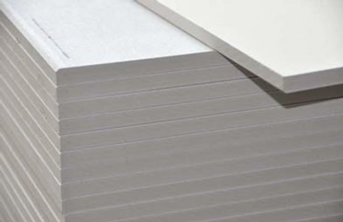
Figure 2. FCB used as frame specimen sheathed.
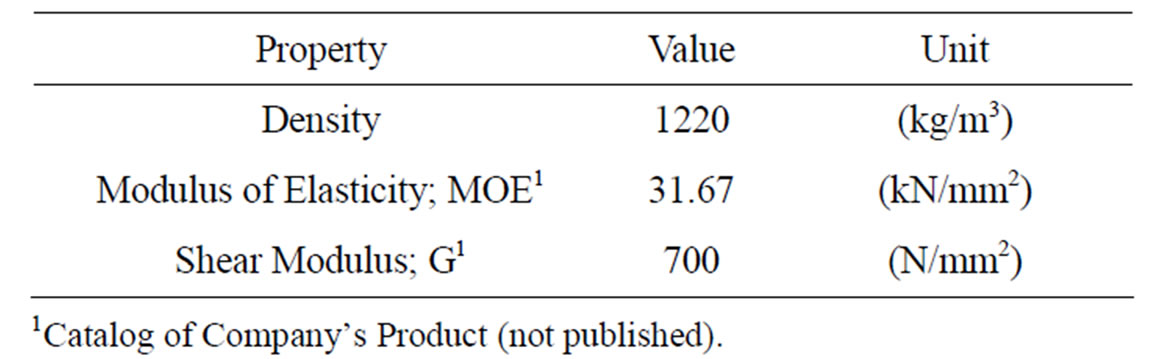
Table 2. Mechanical and physical properties of FCB.

Table 3. Nail specification.

Figure 3. The steel nail used as fastener for all connection.

Figure 4. SWC: the C (Conventional) shear wall frame and nailing pattern.
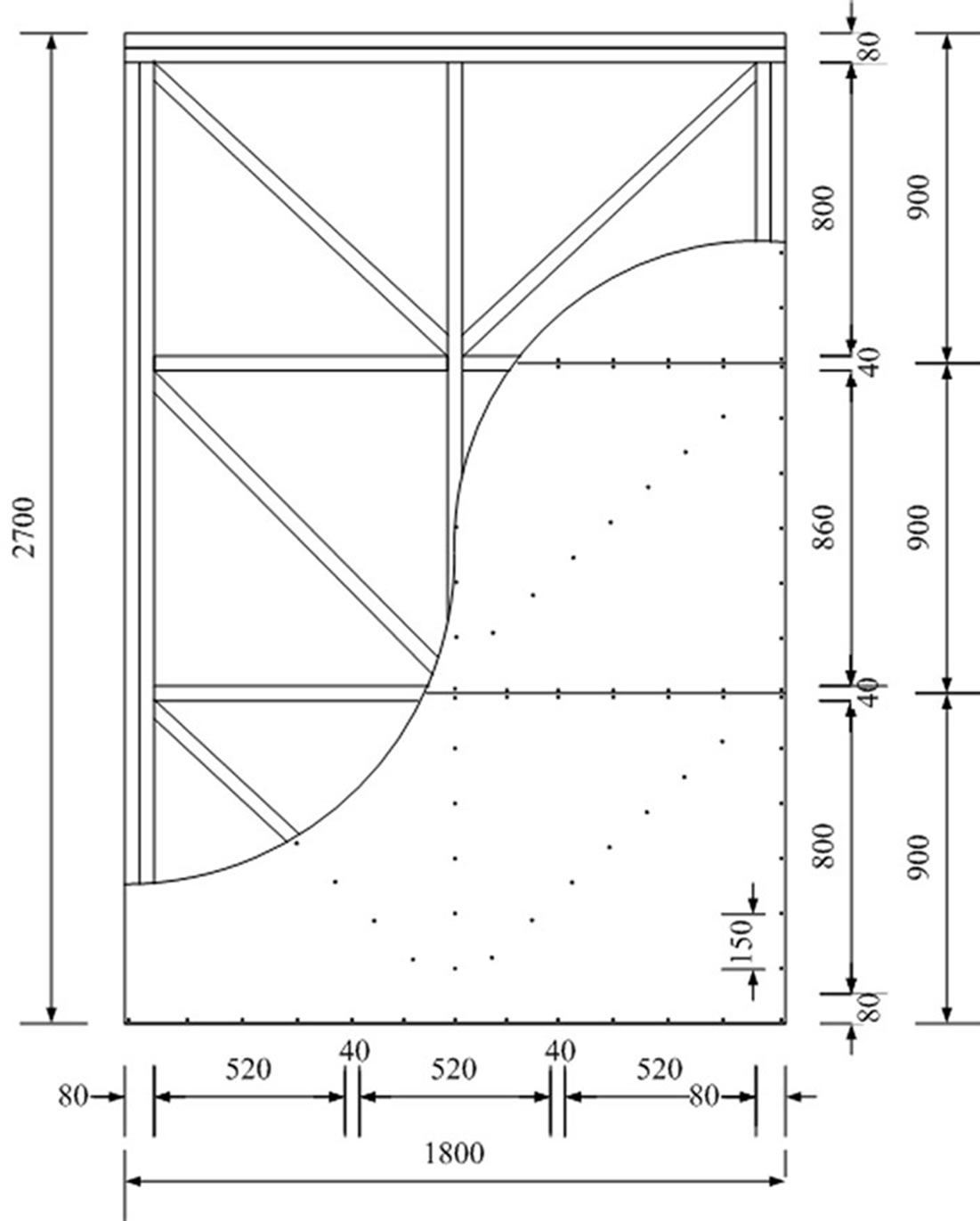
Figure 5. SWB: the V brace shear wall frame and nailing pattern.

Figure 6. Shear test specimen of Akasia wood and FCB fastened by N75 nail.

Figure 7. Shear test specimen of Akasia wood and FCB fastened by N75 nail during test.
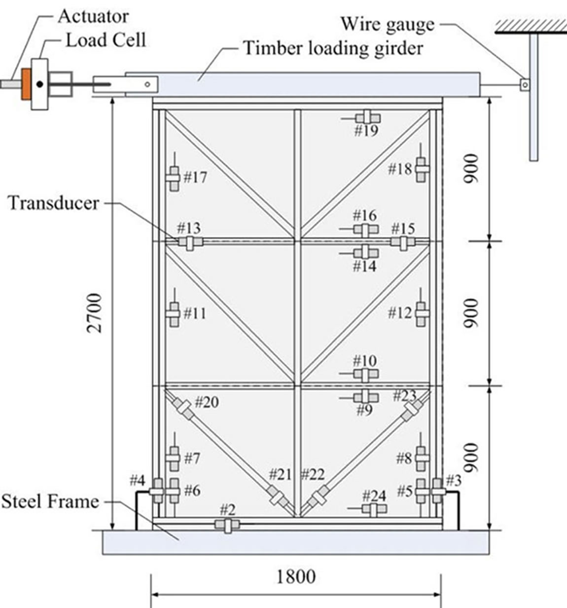
Figure 8. Testing set-up of shear wall specimen.
First loop:  rad Second loop:
  rad Third loop:
  rad Fourth loop:
  rad Fifth loop:
  rad Sixth loop:
  rad Seventh loop:
  rad Eighth loop:
  rad Final loading:
The horizontal push and pull of static cyclic load as represent of earthquake loading was applied using the hydraulic actuator of 500 kN capacity and 500 mm strokes.
The top of shear wall specimen displacement was measured by using displacement-measuring device of 500 mm strokes. Small displacement and rotation of shear wall were measured by using displacement meter of 50 mm strokes. Figures 9 and 10 show the V and C brace and the shear wall specimen during testing.
3. Theory and Calculation
3.1. Analytical Methods for Predicting Envelop Curve
The following nonlinear calculation method was derived based on the article written by Murakami and Inayama [2] but modified so as to be applicable to such nailed-onsheathed shear walls whose nailing pattern are arbitrary arranged.

Figure 9. The V brace frame CFB sheathed during test.

Figure 10. The C brace with CFB sheathed during test.
3.1.1. Derivation of Equations
1) Definition of Nail Position
Figure 11 shows nail positions and rotational center defined in the Cartesian coordinate system where the origin was determined arbitrary to be located at bottom left corner and a total of n nails are located arbitrary starting from I = 1 to nth in a rectangular area of g × L as shown in Figure 11.
Let us assume that slip modulus of nail Ks is not orthotropic but having different values in each nail as this assumption will make it possible to execute step by step nonlinear calculation with considering material nonlinearity of each nail and movement of rotation center from the initial position to any ones which is ought to be determined by equilibrium of nail forces.
2) Derivation of Rotation Center
At first, let us assume a situation that a forced rotational deformation of angle qx was given around the rotation center as shown in Figure 12. Due to this forced
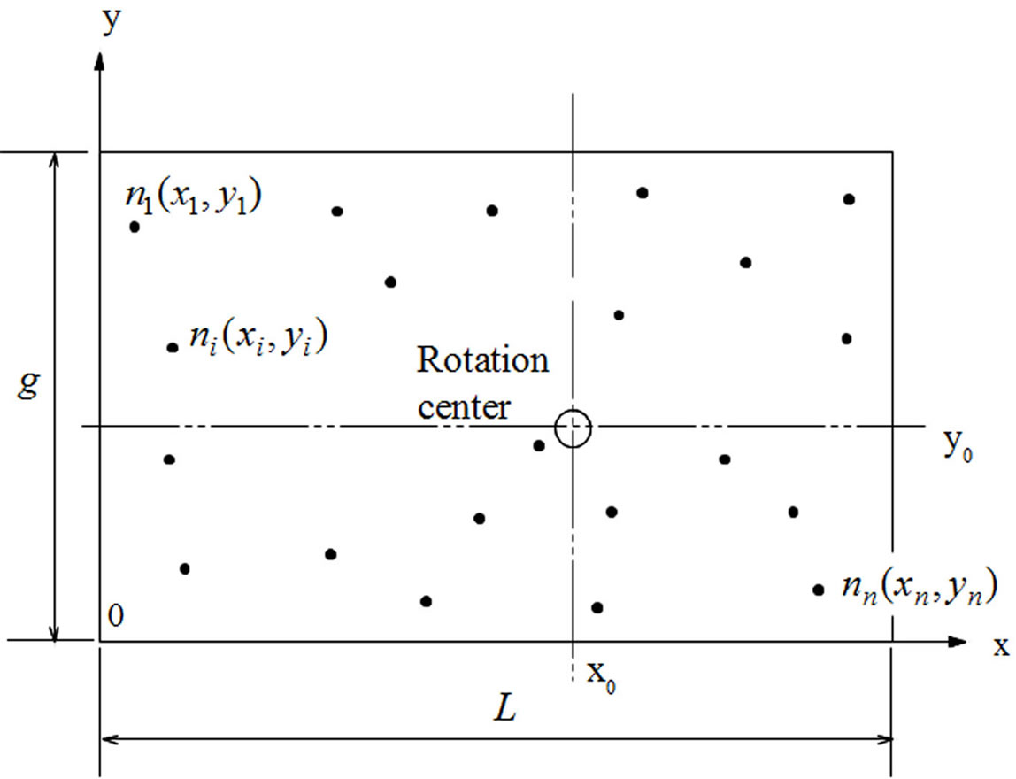
Figure 11. Definition of nail position and rotation center in the Cartesian coordinate system.
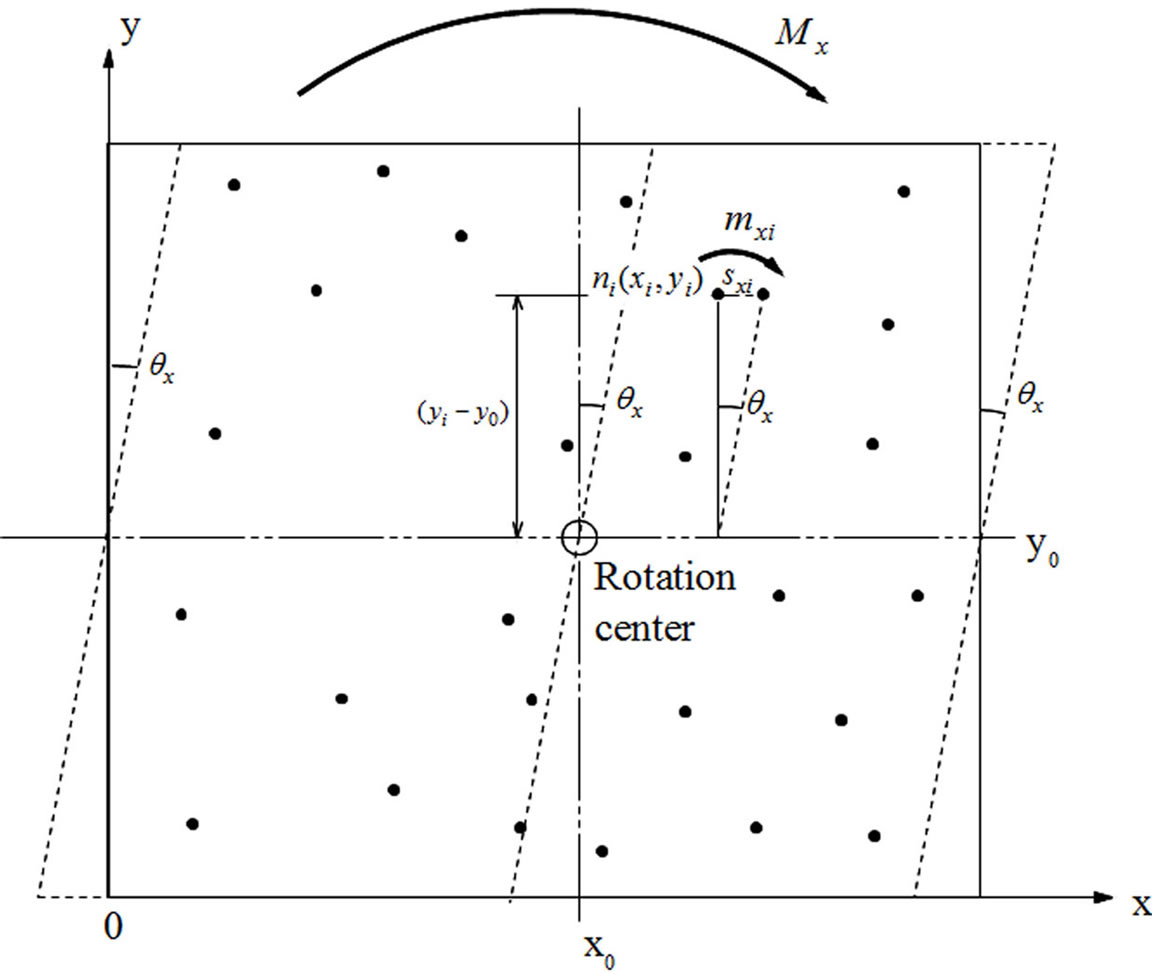
Figure 12. Displacement of ith nail due to forced rotational deformation qx.
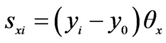
deformation, ith nail ni will be displaced to x-direction by the amount of sxi as shown in Equation (1).
 (1)
(1)
Denoting slip modulus of ith nail as Ksi, the reaction force acting on ith nail can be expressed as Equation (2).
 (2)
(2)
Equilibrium of all pxi along x-direction leads to Equation (3).
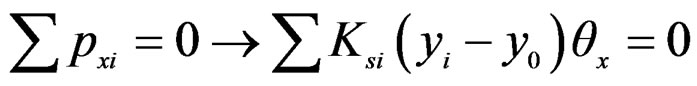 (3)
(3)
As qx is constant, then Equation (3) leads to Equation (4).
 (4)
(4)
From the same derivation process as shown in x-directional case, by assuming forced rotational deformation with angle  as shown in Figure 13, x-directional rotation center can be derived as shown in Equation (5).
 (5)
(5)
3) Derivation of Shear Deformation of Partial Shear Wall
Again let us consider x-directional displacement sxi of ith nail due to qx;
 (6)
(6)
Reaction force acting on the ith nail is;
 (7)
(7)
Individual small rotational moment due to reaction force pxi is;
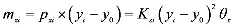 (8)
(8)
x-directional total moment Mx is;
 (9)
(9)
In the same way, y-directional total moment My can be obtained as Equation (10).
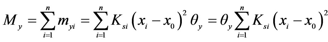 (10)
(10)
As Mx and My must be equilibrium, then Equation (11) should be held good.
 (11)
(11)
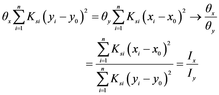 (12)
(12)
While, in Figure 14 shown thatpartial external shear force Q applied on the top of the corresponding shear wall of height “g” gives a rotational moment  and this moment should be equilibrated with each internal moment Mx and My.
 (13)
(13)
The shear deformation angle gn of the shear wall caused
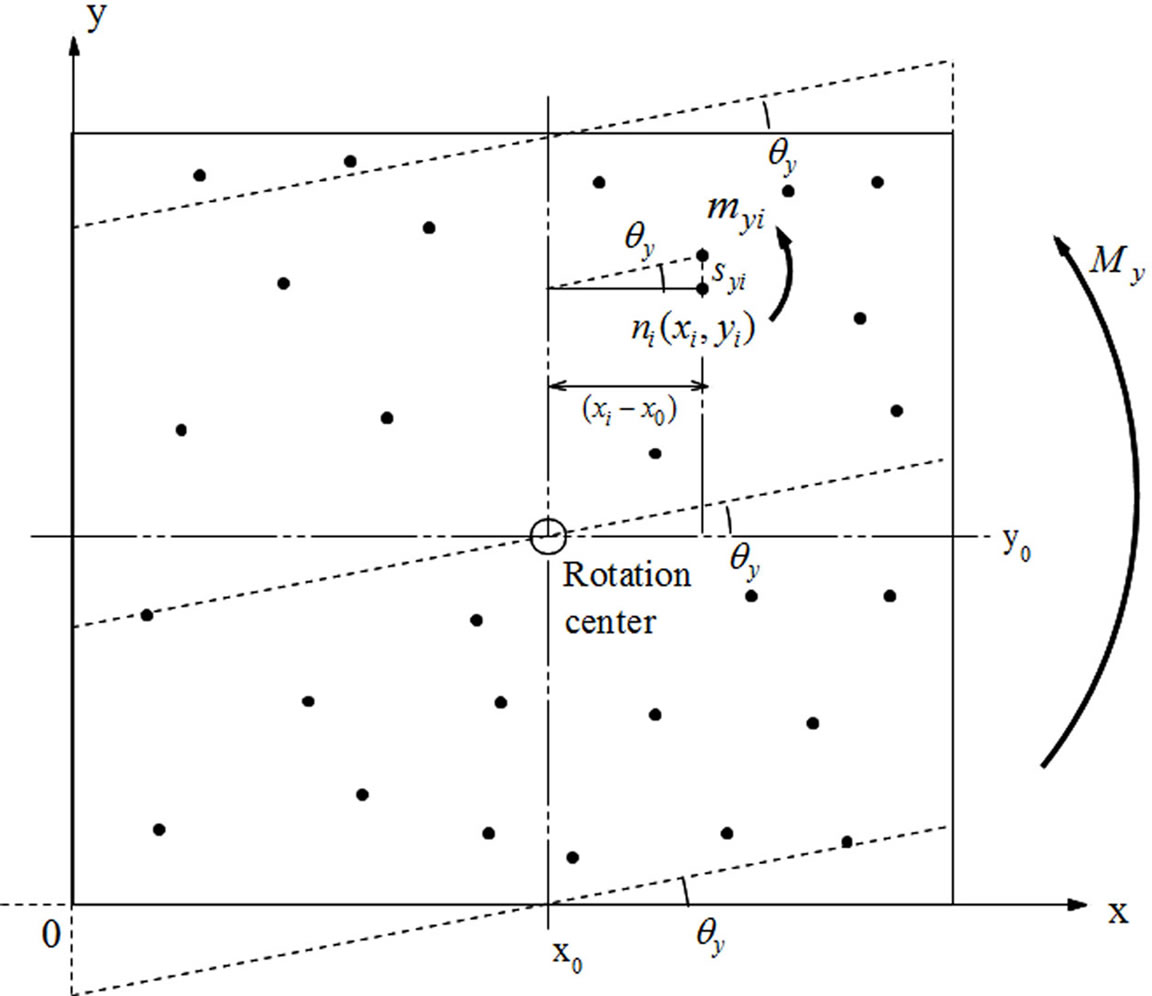
Figure 13. Displacement of ith nail due to forced rotational deformation qy.

Figure 14. Assumed deformation mode in partial shear wall of g × L size.
by nail slip will be defined as the summation of x-directional rotation qx and y-directional rotation qy just same as the definition of shear strain of solid materials, thus,
 (14)
(14)
Substituting Equation (13) into (14), we can get the final relationship between applied shear forces Q and shear deformation angle gn as in Equation (15).
 (15)
(15)
where,

Kn = Shear rigidity component due to nail resistance.
If the shear deformation due to sheathing material itself should be taken into account, the relationship between shear force Q and shear deformation angle gn will be expressed as Equation (16).
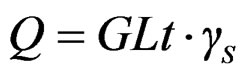 (16)
(16)
where, G is shear rigidity of sheathing materials.
L is length of shear wall.
t is thickness of sheathing materials.
Hence, the total shear deformation angle g of shear wall will be written as the summation of shear deformation angle as;
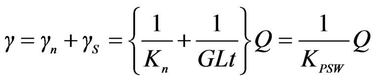 (17)
(17)
where, 
is total shear stiffness of partial shear wall.
4) Derivation of Shear Deformation of Whole Shear Wall
In general, whole shear wall tends to be composed of plural partial shear walls due to unit size of sheathing material as shown in Figure 15.
From equilibrium condition of external and internal moment, Equation (18) should be held good.
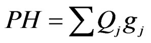 (18)
(18)
The compatibility condition that all partial shear walls should share the same deformation angle will lead to Equation (19),
 (19)
(19)
where, the suffix “j” indicates number of partial shear wall. Substituting Equation (17) into (18) and considering (19), finally we can get Equation (20) for the loadshear deformation relationship of whole shear wall.
 (20)
(20)
3.1.2. Nonlinear Calculation Method
1) Load-Slip Data of Nail for Non-Linear Calculation Method
Figure 16 shows load-slip data of N75 nail taken from single shear test on Akasia wood with FCB sheathing. For this data, a three-parameters exp-equation shown in Equation (21) was fitted up to maximum load for nonlinear calculation. And beyond maximum load level, simple linear equation showed on (22),
 (21)
(21)

Figure 15. Relationship between whole shear wall and partial shear walls.
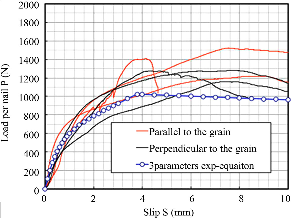
Figure 16. The single nail shear test result.
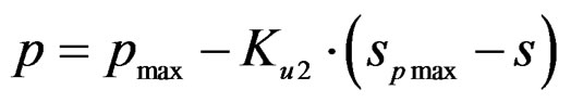 (22)
(22)
where, pu = 550 N, Ku = –10 N/mm, Ks = 1200 N/mm, Ku2 = –10 N/mm.
2) Non-Linear Calculation Procedure
Figure 17 shows flow chart of non-linear calculation procedure in this study.
3.2. Modeling of Hysteresis Loop
In order to analyze dynamic property of shear walls it is necessary to established any appropriate hysteresis loop model. In this study we adopted so-called Normalized Characteristic Loop (NCL) Model that was proposed by Tani and Nomura [3,4] for reinforced concrete structures and recently modified by Matsunaga, Miyazu and Soda [5-7] for timber shear structures.

Figure 17. Flow chart of non-linear calculation procedure.
Figures 18 and 19 show the NCL Model for Akasia frame and FCB sheathing shear wall system were expressed by following Equation (23) in accordance with the studies of Matsunaga, Miyazu and Soda [5-7],
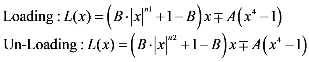 (23)
(23)
where, L(x) and x are normalized load and deformation angle respectively divided by maximum value in each loop and A, B, n1 and n2 are parameters governing shape of hysteretic loop. In the second term of Equation (23), the minus mark should be used in the case of upper curve while plus mark should be used in the case of lower curve. Four parameters are shown in Table 4.

Figure 18. NCL model for conventional type shear wall (SWC).

Figure 19. NCL model for V-brace type shear wall (SWB).

Table 4. Four parameter of NCL model for shear wall.
4. Results and Discussions
4.1. Envelope Curve
Figures 20 and 21 show comparisons between predicted envelope curve and experimental ones. As can be seen from SWC specimens, prediction coincident with experimental ones well, while in the case of SWB specimen, prediction over-estimated performances of shear walls after yielding a little bit. The reason why only one specimen was used for the comparison in SWB specimen is that in experimental procedure, tests were carried out for two specimens without sufficient restriction from up-lift of test specimens. Therefore, the load-deformation curves of those specimens without restriction became abnormal. The rest of one specimen was tested with sufficient restriction for up-lift thus normal load-deformation curve that was usable for the comparison between experiment and prediction was obtained. Therefore, the discrepancy for SWB specimen might be fallen down into the experimental variance.
Figure 22 shows initial failure at edge nail, which occurs at 1/75 radian deformation angle due to insufficient edge distance. This kind of initial failure could not be predicted by the theory derived in this study therefore in order to predict this kind of initial failure precisely, nail shear data having effect of insufficient edge distance should be used in the analysis. Figure 23 shown failure of FCB at 1/15 radian.
4.2. Whole Load Deformation Curve
Figures 24 and 25 show comparisons between experimental

Figure 20. Comparison between predicted envelope curve and experimental result for conventional shear wall (SWC).

Figure 21. Comparison between predicted envelope curve and experimental result for brace type shear wall (SWB).
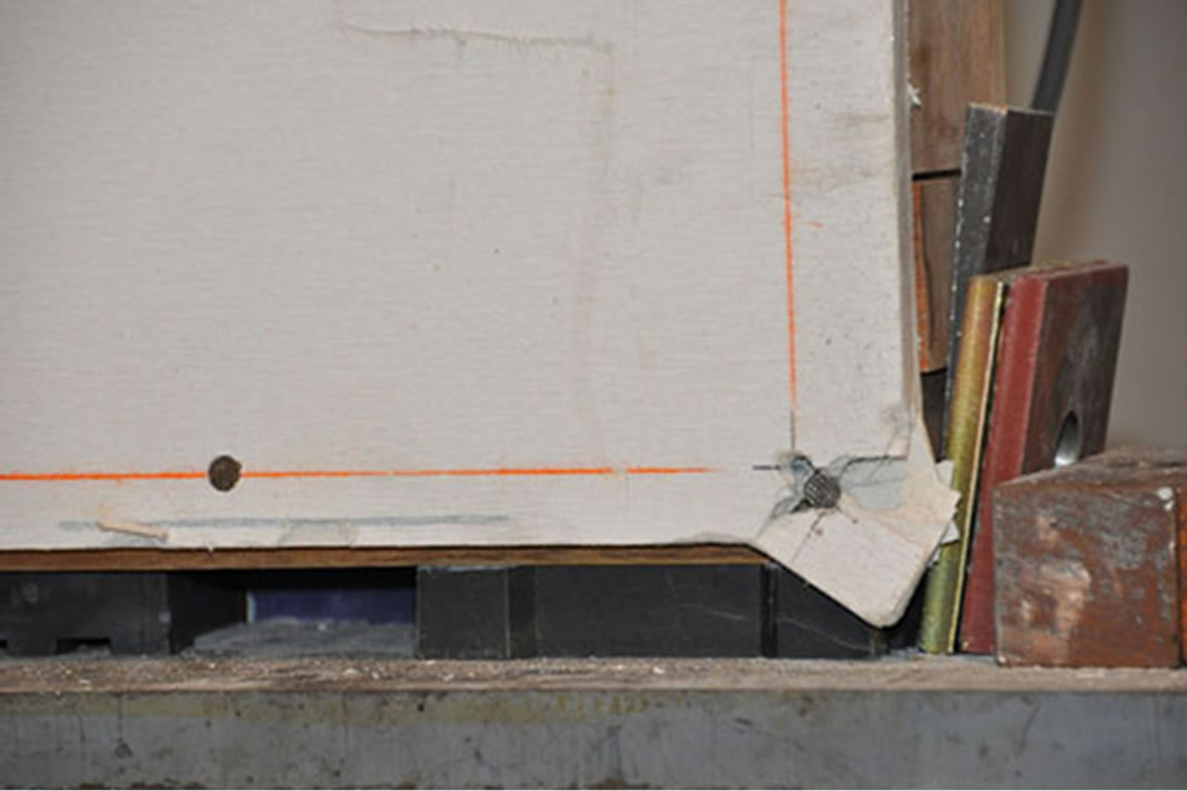
Figure 22. Initial failure at edge nail in 1/75 radian deformation level.

Figure 23. The specimen at final condition in 1/15 radiandeformation level.
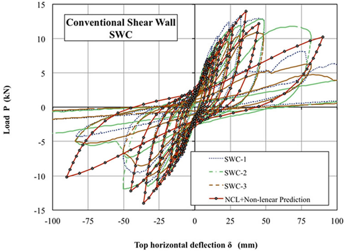
Figure 24. Comparison between predicted load deformation curve and experimental ones for SWC specimen.

Figure 25. Comparison between predicted load deformation curve and experimental ones for SWB specimen.
curve and theoretical prediction, which was obtained by combining, envelop curve with hysteresis NCL Model.
Although there are some sorts of discrepancy between prediction and experimental results, comparisons shown in this study seemed to be fairy good at least for predicting whole nonlinear behaviors of wooden shear walls whose nailing pattern are arbitrary arranged. These comparisons might suggest that better prediction will be obtained by paying careful attention to nail shear data so as to be reflected by in sufficient edge distance effect.
5. Conclusion
In this study we derived a non-linear calculation method for predicting whole load-deformation curve of FCB sheathed nail-on shear wall made by Akasia wood frame.
NCL Model formulated hysteresis loops. By combining these two theoretical methods we could predict whole nonlinear cyclic load-deformation behavior of specimens. Although there were some discrepancies between prediction and experimental observations, further better prediction might be obtain by paying careful attentions to nail shear data so as to be reflected in sufficient edge distance effect.
6. Acknowledgements
We would like to express our sincere thanks to JSPS for Ronpaku program, Structural Function Laboratory, RISH, Kyoto University, Japan, Dr. Akihisa Kitamori, Structural Function Laboratory, RISH, Kyoto University, Japanand RIHS, Ministry of Public Works of Indonesia for all research activity.
REFERENCES
- M. Hadi, S. Murakami, A. Kitamori, W.-S. Chang and K. Komatsu, “Performance of Shear Wall Composed of LVL and Cement Fiber Board Sheathing,” Journal of Asian Architecture and Building Engineering, Vol. 9, No. 2, 2010, pp. 463-469. doi:10.3130/jaabe.9.463
- M. Murakami and M. Inayama, “Formulae to Predict the Elastic and Plastic Behaviour of Shearwall with Any Nailing Arrangement Pattern,” Journal of Structural and Construction Engineering, Transactions of AIJ, Vol. 519, 1999, pp. 87-93.
- S. Tani, S. Nomura, T. Nagasawa and A. Hiramatsu, “Restoring Force Characteristics of Reinforced Concrete Aseismatic Elements (Part 1): Restoring Force Characteristics and Metallization,” Transactions of Architectural Institute of Japan, Vol. 202, 1972, pp. 11-19.
- S. Tani, S. Nomura, T. Nagasawa and A. Hiramatsu, “Restoring Force Characteristics of Reinforced Concrete Seismic Elements (Part 3): Restoring Force Characteristics on Dynamic Response of Structure,” Transactions of Architectural Institute of Japan, Vol. 228, 1975, pp. 39-48.
- H. Matsunaga, S. Soda and Y. Miyazu, “Modeling of Restoring Force Characteristics of Wooden Structures and Its Application to Dynamic Analyses,” Proceeding of the 78th Architectural Research Meetings, 2007, Architectural Institute of Japan, Kanto Chapter, 2008, pp. 201-204.
- H. Matsunaga, Y. Miyazu and S. Soda, “Time History Seismic Response Analysis for Wooden Structure Applied Extended NCL Model,” Summaries of Technical Papers of Annual Meeting Architectural Institute of Japan. C-1, Structures III, 2008, pp. 181-182.
- H. Matsunaga, Y. Miyazu and S. Soda, “A Universal Modeling Method for Wooden Shear/Nonshear Walls,” Journal of Structural and Construction Engineering, Transactions of AIJ, No. 639, 2009, pp. 889-896.