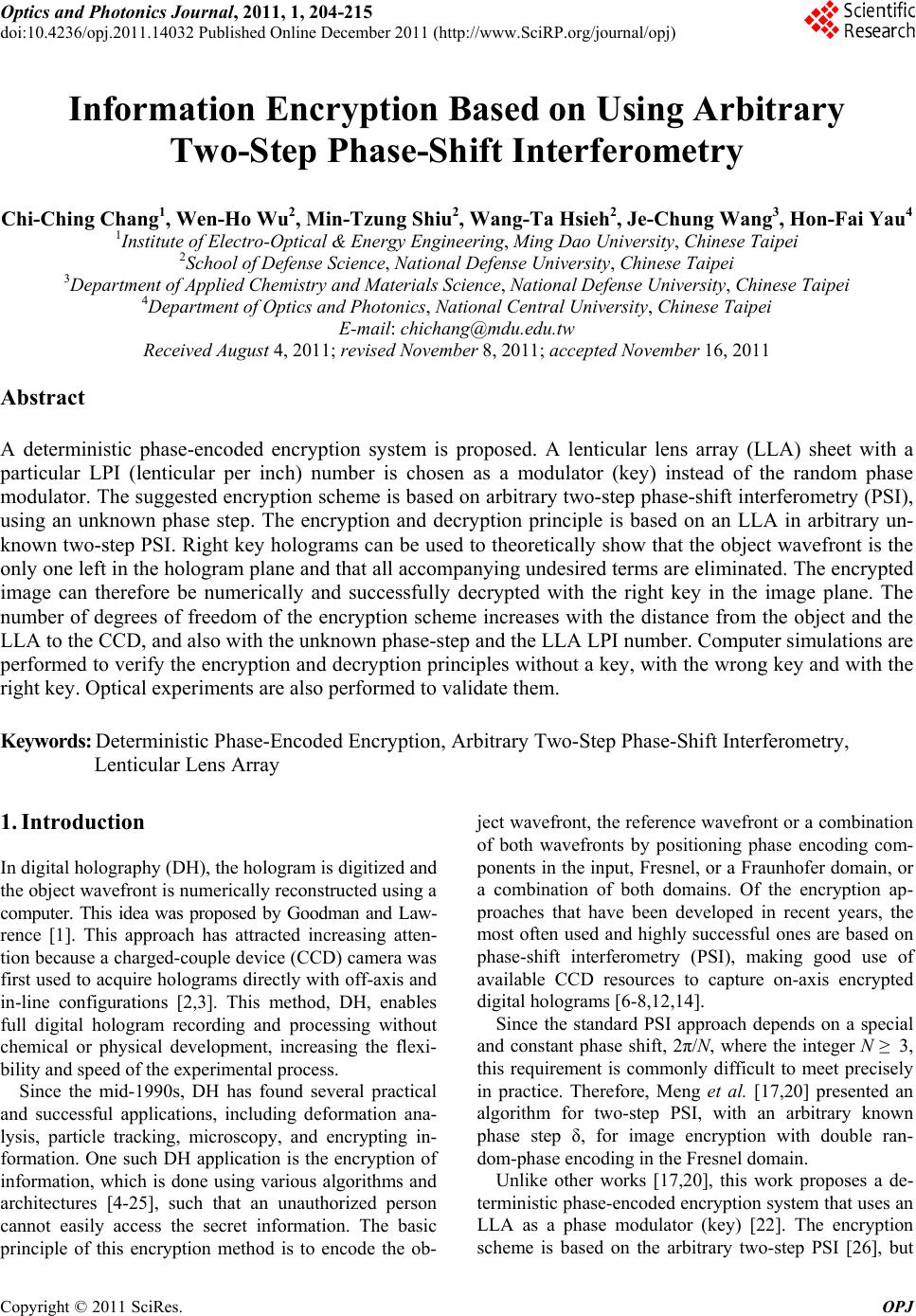
 Optics and Photonics Journal, 2011, 1, 204-215 doi:10.4236/opj.2011.14032 Published Online December 2011 (http://www.SciRP.org/journal/opj) Copyright © 2011 SciRes. OPJ Information Encryption Based on Using Arbitrary Two-Step Phase-Shift Interferometry Chi-Ching Chang1, Wen-Ho Wu2, Min-Tzung Shiu2, Wang-Ta Hsieh2, Je-Chung Wang3, Hon-Fai Yau4 1Institute of Electro-Optical & Energy Engineering, Ming Dao University, Chinese Taipei 2School of Defense Science, National Defense University, Chinese Taipei 3Department of Applied Chemistry and Materials Science, National Defense University, Chinese Taipei 4Department of Optics and Photonics, National Central University, Chinese Taipei E-mail: chichang@mdu.edu.tw Received August 4, 2011; revised November 8, 2011; accepted November 16, 2011 Abstract A deterministic phase-encoded encryption system is proposed. A lenticular lens array (LLA) sheet with a particular LPI (lenticular per inch) number is chosen as a modulator (key) instead of the random phase modulator. The suggested encryption scheme is based on arbitrary two-step phase-shift interferometry (PSI), using an unknown phase step. The encryption and decryption principle is based on an LLA in arbitrary un- known two-step PSI. Right key holograms can be used to theoretically show that the object wavefront is the only one left in the hologram plane and that all accompanying undesired terms are eliminated. The encrypted image can therefore be numerically and successfully decrypted with the right key in the image plane. The number of degrees of freedom of the encryption scheme increases with the distance from the object and the LLA to the CCD, and also with the unknown phase-step and the LLA LPI number. Computer simulations are performed to verify the encryption and decryption principles without a key, with the wrong key and with the right key. Optical experiments are also performed to validate them. Keywords: Deterministic Phase-Encoded Encryption, Arbitrary Two-Step Phase-Shift Interferometry, Lenticular Lens Array 1. Introduction In digital holography (DH), the hologram is digitized and the object wavefront is numerically reconstructed using a computer. This idea was proposed by Goodman and Law- rence [1]. This approach has attracted increasing atten- tion because a charged-couple device (CCD) camera was first used to acquire holograms directly with off-axis and in-line configurations [2,3]. This method, DH, enables full digital hologram recording and processing without chemical or physical development, increasing the flexi- bility and speed of the experimental process. Since the mid-1990s, DH has found several practical and successful applications, including deformation ana- lysis, particle tracking, microscopy, and encrypting in- formation. One such DH application is the encryption of information, which is done using various algorithms and architectures [4-25], such that an unauthorized person cannot easily access the secret information. The basic principle of this encryption method is to encode the ob- ject wavefront, the reference wavefront or a combination of both wavefronts by positioning phase encoding com- ponents in the input, Fresnel, or a Fraunhofer domain, or a combination of both domains. Of the encryption ap- proaches that have been developed in recent years, the most often used and highly successful ones are based on phase-shift interferometry (PSI), making good use of available CCD resources to capture on-axis encrypted digital holograms [6-8,12,14]. Since the standard PSI approach depends on a special and constant phase shift, 2π/N, where the integer N ≥ 3, this requirement is commonly difficult to meet precisely in practice. Therefore, Meng et al. [17,20] presented an algorithm for two-step PSI, with an arbitrary known phase step δ, for image encryption with double ran- dom-phase encoding in the Fresnel domain. Unlike other works [17,20], this work proposes a de- terministic phase-encoded encryption system that uses an LLA as a phase modulator (key) [22]. The encryption scheme is based on the arbitrary two-step PSI [26], but 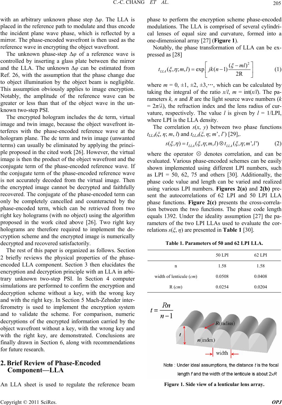 205 C.-C. CHANG ET AL. with an arbitrary unknown phase step Δφ. The LLA is placed in the reference path to modulate and thus encode the incident plane wave phase, which is reflected by a mirror. The phase-encoded wavefront is then used as the reference wave in encrypting the object wavefront. The unknown phase-step Δφ of a reference wave is controlled by inserting a glass plate between the mirror and the LLA. The unknown Δφ can be estimated from Ref. 26, with the assumption that the phase change due to object illumination by the object beam is negligible. This assumption obviously applies to image encryption. Notably, the amplitude of the reference wave can be greater or less than that of the object wave in the un- known two-step PSI. The encrypted hologram includes the dc term, virtual image and twin image, because the object wavefront in- terferes with the phase-encoded reference wave at the hologram plane. The dc term and twin image (unwanted terms) can usually be eliminated by applying the princi- ple proposed in the cited work [26]. However, the virtual image is then the product of the object wavefront and the conjugate term of the phase-encoded reference wave. If the conjugate term of the phase-encoded reference wave is not accurately decoded from the virtual image. Then the encrypted image cannot be decrypted and faithfully recovered. The conjugate of the phase-encoded term can only be completely cancelled and counteracted by the phase-encoded term, which can be retrieved from two right key holograms (with no object) using the algorithm proposed in the work cited above [26]. Two right key holograms are therefore required to implement the de- cryption scheme and the encrypted image is numerically decrypted and recovered satisfactorily. The rest of this paper is organized as follows. Section 2 briefly reviews the physical properties of the phase- encoded LLA component. Section 3 then elucidates the encryption and decryption principle with an LLA in arbi- trary unknown two-step PSI. In Section 4 computer simulations are performed to confirm the encryption and decryption scheme without a key, with the wrong key and with the right key. In Section 5 Mach-Zehnder inter- ferometry is used to implement the encryption system and to validate the scheme. For comparison, numeric decryptions of the encrypted information carried by the object wavefront without a key, with the wrong key and with the right key, are demonstrated. Conclusions are finally drawn in Section 6, along with recommendations for future research. 2. Brief Review of Phase-Encoded Component—LLA An LLA sheet is used to regulate the reference beam phase to perform the encryption scheme phase-encoded modulations. The LLA is comprised of several cylindri- cal lenses of equal size and curvature, formed into a one-dimensional array [27] (Figure 1). Notably, the phase transformation of LLA can be ex- pressed as [28] 2 () (,; ,)exp(1)2R LLA ml tml jkn (1) where m = 0, ±1, ±2, ±3,…, which can be calculated by taking the integral of the ratio x/l, m = int(x/l). The pa- rameters k, n and R are the light source wave numbers (k = 2π/λ), the refraction index and the lens radius of cur- vature, respectively. The value l is given by l = 1/LPI, where LPI is the LLA density. The correlation s(x, y) between two phase functions tLLA(ξ, η; m, l) and tLLA(ξ, η; m’, l’) [29],. (,)(,; ,)(,;',') LLA LLA tmltml (2) where the operator ○ × denotes correlation, and can be evaluated. Various phase-encoded schemes can be easily shown implemented using different LPI numbers, such as LPI = 50, 62, 75 and others [30]. Additionally, the phase code value and length can be varied and realized using various LPI numbers. Figures 2(a) and 2(b) pre- sent the autocorrelations of 62 LPI and 50 LPI LLA phase functions. Figure 2(c) presents the cross-correla- tion between the two functions. The phase code length equals 1392. Under the ideality assumption [27] the pa- rameters of the two LPI LLAs used to evaluate the cor- relations s(ξ, η) are presented in Table 1 [30]. Table 1. Parameters of 50 and 62 LPI LLA. 50 LPI 62 LPI n 1.58 1.58 width of lenticule (cm) 0.0508 0.0408 R (cm) 0.0254 0.0204 Figure 1. Side view of a lenticular lens array. Copyright © 2011 SciRes. OPJ 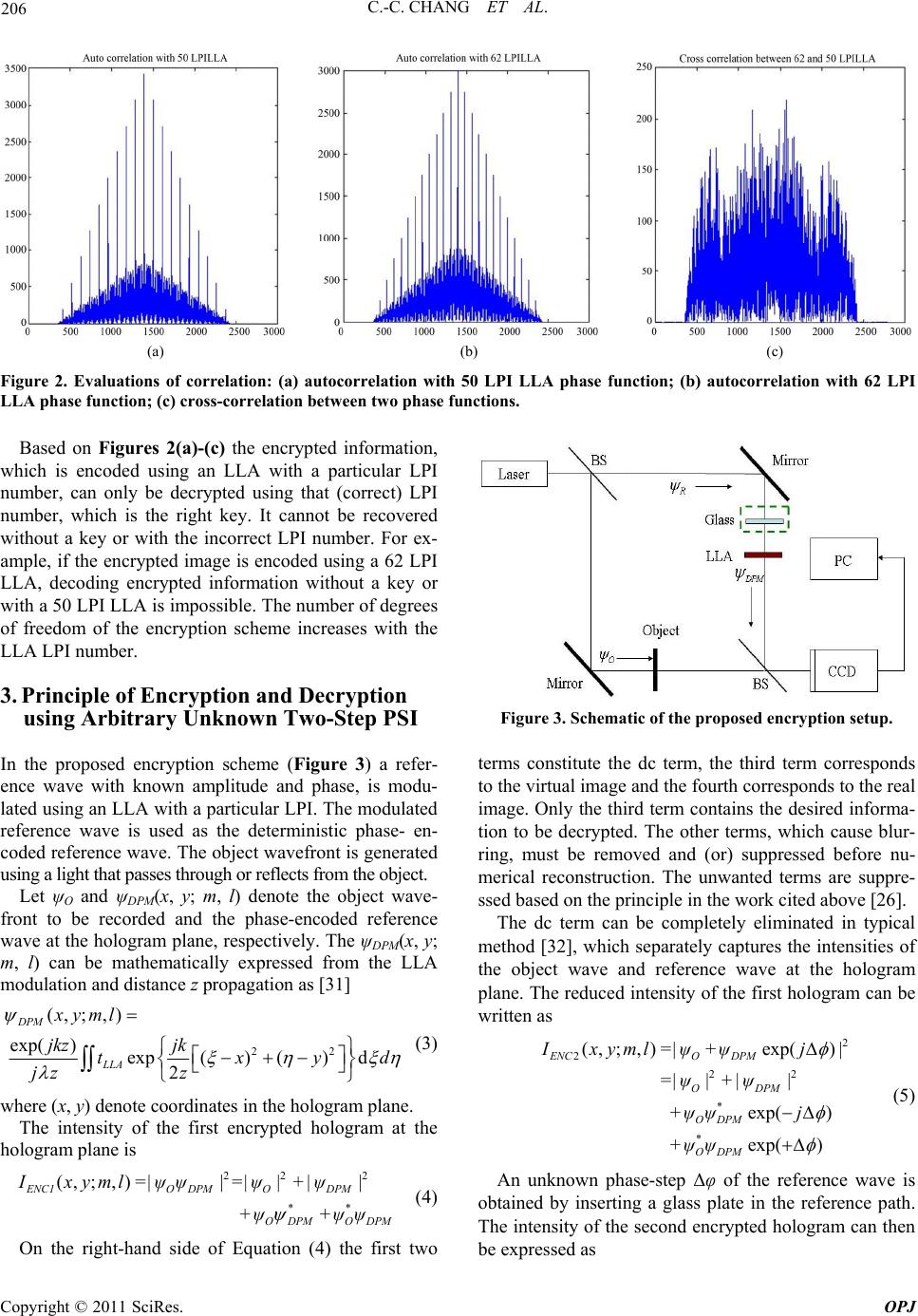 C.-C. CHANG ET AL. Copyright © 2011 SciRes. OPJ 206 (a) (b) (c) Figure 2. Evaluations of correlation: (a) autocorrelation with 50 LPI LLA phase function; (b) autocorrelation with 62 LPI LLA phase function; (c) cross-correlation between two phase functions. Based on Figures 2(a)-(c) the encrypted information, which is encoded using an LLA with a particular LPI number, can only be decrypted using that (correct) LPI number, which is the right key. It cannot be recovered without a key or with the incorrect LPI number. For ex- ample, if the encrypted image is encoded using a 62 LPI LLA, decoding encrypted information without a key or with a 50 LPI LLA is impossible. The number of degrees of freedom of the encryption scheme increases with the LLA LPI number. 3. Principle of Encryption and Decryption using Arbitrary Unknown Two-Step PSI Figure 3. Schematic of the proposed encryption setup. terms constitute the dc term, the third term corresponds to the virtual image and the fourth corresponds to the real image. Only the third term contains the desired informa- tion to be decrypted. The other terms, which cause blur- ring, must be removed and (or) suppressed before nu- merical reconstruction. The unwanted terms are suppre- ssed based on the principle in the work cited above [26]. In the proposed encryption scheme (Figure 3) a refer- ence wave with known amplitude and phase, is modu- lated using an LLA with a particular LPI. The modulated reference wave is used as the deterministic phase- en- coded reference wave. The object wavefront is generated using a light that passes through or reflects from the object. Let ψO and ψDPM(x, y; m, l) denote the object wave- front to be recorded and the phase-encoded reference wave at the hologram plane, respectively. The ψDPM(x, y; m, l) can be mathematically expressed from the LLA modulation and distance z propagation as [31] 22 (, ;,) exp( )exp() ()d 2 DPM LLA xyml jkz jk txy jz z The dc term can be completely eliminated in typical method [32], which separately captures the intensities of the object wave and reference wave at the hologram plane. The reduced intensity of the first hologram can be written as d (3) 2 2 22 * * (, ;,)exp() exp( ) exp( ) ENCO DPM ODPM ODPM ODPM Ixyml=|ψ+ψj| =| ψ|+|ψ| +ψψ j +ψψ (5) where (x, y) denote coordinates in the hologram plane. The intensity of the first encrypted hologram at the hologram plane is An unknown phase-step Δφ of the reference wave is obtained by inserting a glass plate in the reference path. The intensity of the second encrypted hologram can then be expressed as 22 2 ** (, ;,) ENC1O DPMODPM ODPM ODPM Ixyml=|ψψ |=|ψ|+|ψ| +ψ+ψψ (4) On the right-hand side of Equation (4) the first two  207 C.-C. CHANG ET AL. 2 2 22 * * (, ;,)exp() exp( ) exp( ) ENCO DPM ODPM ODPM ODPM Ixyml=|ψ+ψj| =| ψ|+|ψ| +ψψ j +ψψ (6) Similarly, when the dc term is completely suppressed, the reduced intensity of the second hologram is given by '* 2 * (,;, )exp() exp( ) ENCO DPM ODPM Ixyml=ψψj +ψψ (7) From the simple argument in the cited work [26], the unknown phase-step can be easily estimated with limited pixels near the optical axis (in discrete form) as '(,) cos[( , )] '(,) ENC2 ENC1 Ipq pq Ipq (8) where p = 1,…, M and q = 1,…, N and M × N is the number of light-sensitive pixels on the CCD, respec- tively. Alternatively, Δφ can be estimated using the Fou- rier transform ratio of their reduced intensities with the same approximations, 1 'cos( ) ' ENC2 ENC I I (9) Let Equation (7) be multiplied by the term exp(–jΔφ) and then subtracted from Equation (5). The following equation is obtained. * * 'exp() '1exp(2) (,)(,; ,) ENC1 ENC2 ODPM ODPM IjI j pq pqml (10) since Δφ can be regarded as fixed in the recording stage in the arbitrary two phase-step approach, the twin-image is satisfactorily and completely eliminated by the nu- merical operations performed using the reduced intensi- ties of the two holograms and the estimated value of Δφ. However, the right-hand side of Equation (10) is now seen to be composed of the object wavefront ψO and the conjugate term of ψDPM(p, q; m, l), which is abbreviated as ψDPM(m, l) hereafter. If the conjugate term of ψDPM(m, l) cannot be determined by decoding the virtual image and thus separated from ψO, the encrypted image will then not to be decrypted or faithfully recovered from the encrypted holograms. To accurately decode the conju- gate term of ψDPM(m, l) from Equation (10), two addi- tional right key holograms must be recorded using the right key, which can be easily and mathematically con- firmed by the arguments below. For comparison, the encrypted information about the object wavefront will be numerically decrypted without a key, with a wrong key and with the right key. 3.1. Decryption without Key For decryption with no key, the abbreviation * (,; ,)(,)(,) ENCh ODPM Upqmlpq ml (11) is applied in the hologram plane. Then, let UENC be di- rectly reconstructed in the image plane using the convo- lution approach [33] * (,)(,)( ) -1 ODPMi ENC pqml=Uhz d (12) where h (z = d) represents the impulse response through a distance z = d. As expected, the left-hand side of Equation (12) still contains the product of ψO and the conjugate term of ψDPM(m, l), so the encrypted image is not successfully decrypted in this case. 3.2. Decryption with Wrong Key - Incorrect LPI LLA (m’≠m and l’≠l) Let two wrong key (incorrect LPI LLA) holograms (with no object), IKEY1(m’, l’) and IKEY2(m’, l’), be captured by the arbitrary two-step PSI method. According to similar nu- merical procedures derived from Equations (10)-(12), the phase-encoded pattern term ψDPM(m’, l’ ) and reconstructed object wavefront can be straightforward written down ( ',')'( ',')exp()'(',') (',') KEYh KEY1KEY2 DPM UmlImlj Iml ml (13a) * ,; ,,',' (,) ,',' Oi -1 ODPM DPM ψpqmlm l =pqmlm hz d l (14a) Based on the right-hand side of Equation (14a), if the incorrect LPI LLA (wrong key) is used, the conjugate term of ψDPM(m, l) will not be fully separated from the object wavefront term. Since the conjugate term cannot be completely cancelled by ψDPM(m’, l’), the encrypted image cannot be recovered from the encrypted holo- grams with the aid of a wrong key. 3.3. Decryption with Right Key - Correct LPI LLA (m’=m and l’=l) Let two wrong key (incorrect LPI LLA) holograms (with no object), IKEY1(m’, l’) and IKEY2(m’, l’), be captured by the arbitrary two-step PSI method. According to similar numerical procedures derived from Equations (10)-(12), the phase-encoded pattern term ψDPM(m’, l’) and recon- structed object wavefront can be straightforward written down Copyright © 2011 SciRes. OPJ 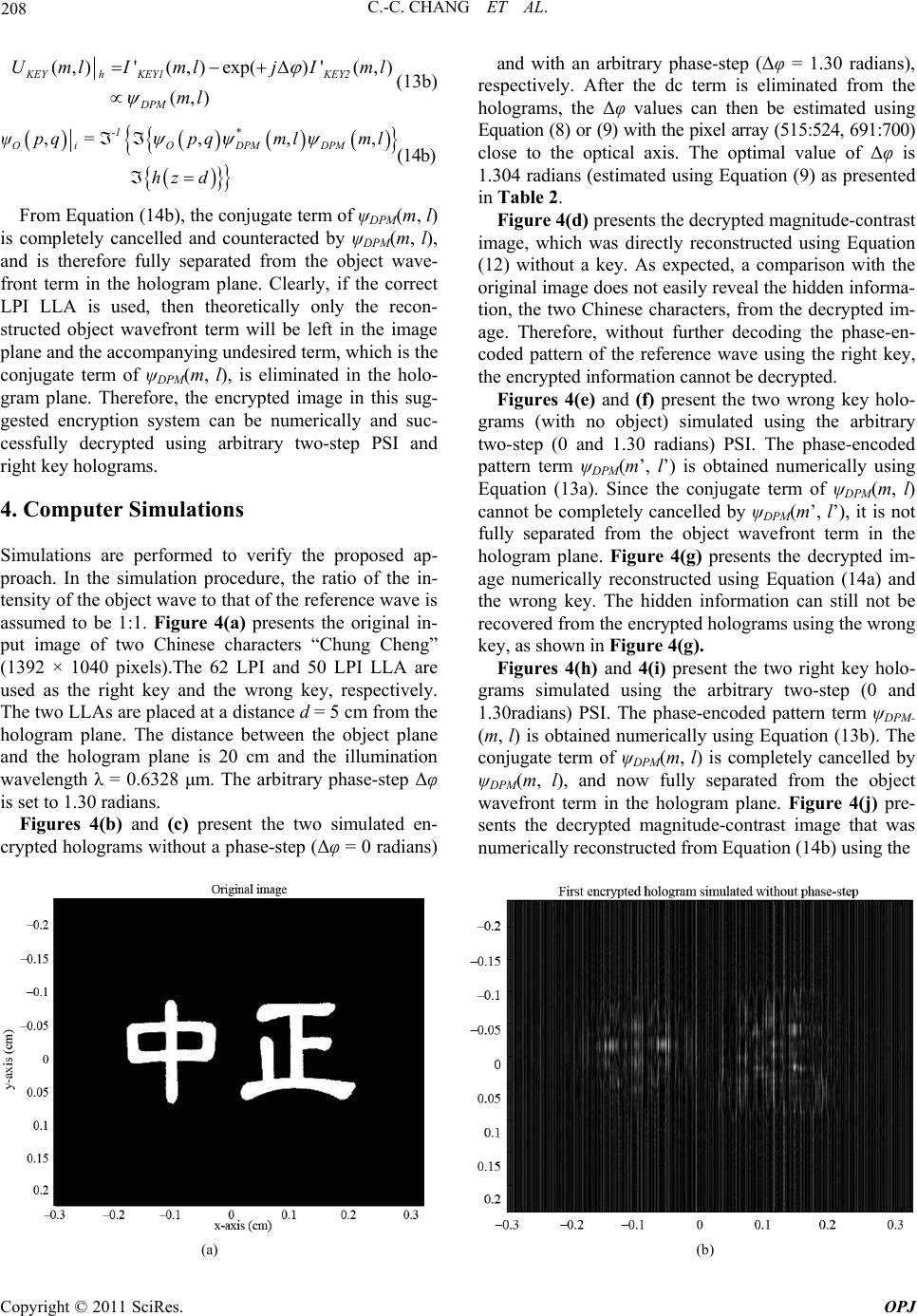 C.-C. CHANG ET AL. Copyright © 2011 SciRes. OPJ 208 (,)'(,)exp()'(,) (,) KEYh KEY1KEY2 DPM UmlImlj Iml ml (13b) * ,,, -1 OiODPM DPM ψpq =pqmlml hz d , (14b) and with an arbitrary phase-step (Δφ = 1.30 radians), respectively. After the dc term is eliminated from the holograms, the Δφ values can then be estimated using Equation (8) or (9) with the pixel array (515:524, 691:700) close to the optical axis. The optimal value of Δφ is 1.304 radians (estimated using Equation (9) as presented in Table 2. From Equation (14b), the conjugate term of ψDPM(m, l) is completely cancelled and counteracted by ψDPM(m, l), and is therefore fully separated from the object wave- front term in the hologram plane. Clearly, if the correct LPI LLA is used, then theoretically only the recon- structed object wavefront term will be left in the image plane and the accompanying undesired term, which is the conjugate term of ψDPM(m, l), is eliminated in the holo- gram plane. Therefore, the encrypted image in this sug- gested encryption system can be numerically and suc- cessfully decrypted using arbitrary two-step PSI and right key holograms. Figure 4(d) presents the decrypted magnitude-contrast image, which was directly reconstructed using Equation (12) without a key. As expected, a comparison with the original image does not easily reveal the hidden informa- tion, the two Chinese characters, from the decrypted im- age. Therefore, without further decoding the phase-en- coded pattern of the reference wave using the right key, the encrypted information cannot be decrypted. Figures 4(e) and (f) present the two wrong key holo- grams (with no object) simulated using the arbitrary two-step (0 and 1.30 radians) PSI. The phase-encoded pattern term ψDPM(m’, l’) is obtained numerically using Equation (13a). Since the conjugate term of ψDPM(m, l) cannot be completely cancelled by ψDPM(m’, l’), it is not fully separated from the object wavefront term in the hologram plane. Figure 4(g) presents the decrypted im- age numerically reconstructed using Equation (14a) and the wrong key. The hidden information can still not be recovered from the encrypted holograms using the wrong key, as shown in Figure 4(g). 4. Computer Simulations Simulations are performed to verify the proposed ap- proach. In the simulation procedure, the ratio of the in- tensity of the object wave to that of the reference wave is assumed to be 1:1. Figure 4(a) presents the original in- put image of two Chinese characters “Chung Cheng” (1392 × 1040 pixels).The 62 LPI and 50 LPI LLA are used as the right key and the wrong key, respectively. The two LLAs are placed at a distance d = 5 cm from the hologram plane. The distance between the object plane and the hologram plane is 20 cm and the illumination wavelength λ = 0.6328 μm. The arbitrary phase-step Δφ is set to 1.30 radians. Figures 4(h) and 4(i) present the two right key holo- grams simulated using the arbitrary two-step (0 and 1.30radians) PSI. The phase-encoded pattern term ψDPM- (m, l) is obtained numerically using Equation (13b). The conjugate term of ψDPM(m, l) is completely cancelled by ψDPM(m, l), and now fully separated from the object wavefront term in the hologram plane. Figure 4(j) pre- sents the decrypted magnitude-contrast image that was numerically reconstructed from Equation (14b) using the Figures 4(b) and (c) present the two simulated en- crypted holograms without a phase-step (Δφ = 0 radians) (a) (b) 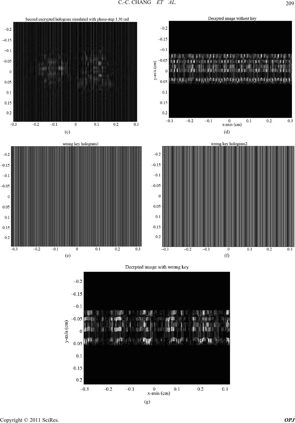 209 C.-C. CHANG ET AL. (c) (d) (e) (f) (g) Copyright © 2011 SciRes. OPJ 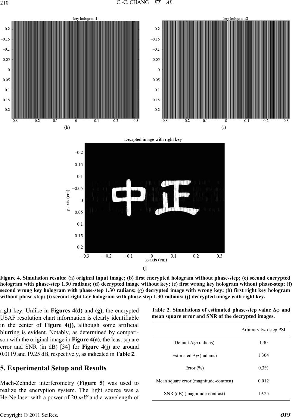 C.-C. CHANG ET AL. Copyright © 2011 SciRes. OPJ 210 (h) (i) (j) Figure 4. Simulation results: (a) original input image; (b) first encrypted hologram without phase-step; (c) second encrypted hologram with phase-step 1.30 radians; (d) decrypted image without key; (e) first wrong key hologram without phase-step; (f) second wrong key hologram with phase-step 1.30 radians; (g) decrypted image with wrong key; (h) first right key hologram without phase-step; (i) second right key hologram with phase-step 1.30 radians; (j) decrypted image with right key. Table 2. Simulations of estimated phase-step value Δφ and mean square error and SNR of the decrypted images. right key. Unlike in Figures 4(d) and (g), the encrypted USAF resolution chart information is clearly identifiable in the center of Figure 4(j), although some artificial blurring is evident. Notably, as determined by compari- son with the original image in Figure 4(a), the least square error and SNR (in dB) [34] for Figure 4(j) are around 0.0119 and 19.25 dB, respectively, as indicated in Table 2. Arbitrary two-step PSI Default (radians) 1.30 Estimated (radians) 1.304 Error (%) 0.3% Mean square error (magnitude-contrast) 0.012 SNR (dB) (magnitude-contrast) 19.25 5. Experimental Setup and Results Mach-Zehnder interferometry (Figure 5) was used to realize the encryption system. The light source was a He-Ne laser with a power of 20 mW and a wavelength of 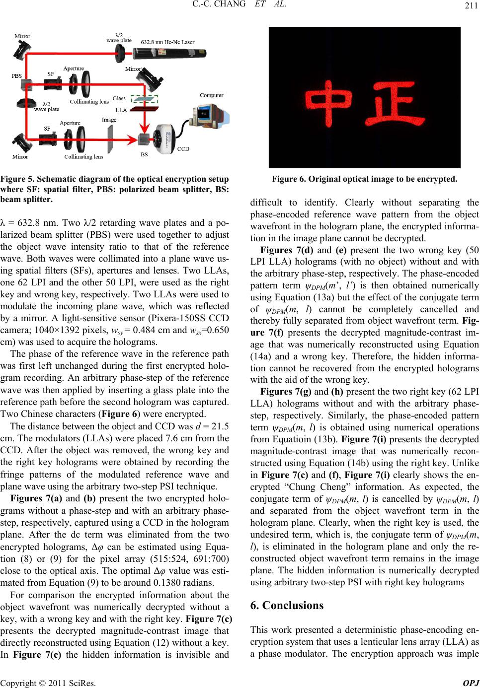 211 C.-C. CHANG ET AL. Figure 5. Schematic diagram of the optical encryption setup where SF: spatial filter, PBS: polarized beam splitter, BS: beam splitter. λ = 632.8 nm. Two λ/2 retarding wave plates and a po- larized beam splitter (PBS) were used together to adjust the object wave intensity ratio to that of the reference wave. Both waves were collimated into a plane wave us- ing spatial filters (SFs), apertures and lenses. Two LLAs, one 62 LPI and the other 50 LPI, were used as the right key and wrong key, respectively. Two LLAs were used to modulate the incoming plane wave, which was reflected by a mirror. A light-sensitive sensor (Pixera-150SS CCD camera; 1040×1392 pixels, wsy = 0.484 cm and wsx=0.650 cm) was used to acquire the holograms. The phase of the reference wave in the reference path was first left unchanged during the first encrypted holo- gram recording. An arbitrary phase-step of the reference wave was then applied by inserting a glass plate into the reference path before the second hologram was captured. Two Chinese characters (Figure 6) were encrypted. The distance between the object and CCD was d = 21.5 cm. The modulators (LLAs) were placed 7.6 cm from the CCD. After the object was removed, the wrong key and the right key holograms were obtained by recording the fringe patterns of the modulated reference wave and plane wave using the arbitrary two-step PSI technique. Figures 7(a) and (b) present the two encrypted holo- grams without a phase-step and with an arbitrary phase- step, respectively, captured using a CCD in the hologram plane. After the dc term was eliminated from the two encrypted holograms, Δφ can be estimated using Equa- tion (8) or (9) for the pixel array (515:524, 691:700) close to the optical axis. The optimal Δφ value was esti- mated from Equation (9) to be around 0.1380 radians. For comparison the encrypted information about the object wavefront was numerically decrypted without a key, with a wrong key and with the right key. Figure 7(c) presents the decrypted magnitude-contrast image that directly reconstructed using Equation (12) without a key. Figure 6. Original optical image to be encrypted. di icthe d a deterministic phase-encoding en- ff ult to identify. Clearly without separating phase-encoded reference wave pattern from the object wavefront in the hologram plane, the encrypted informa- tion in the image plane cannot be decrypted. Figures 7(d) and (e) present the two wrong key (50 LPI LLA) holograms (with no object) without and with the arbitrary phase-step, respectively. The phase-encoded pattern term ψDPM(m’, l’) is then obtained numerically using Equation (13a) but the effect of the conjugate term of ψDPM(m, l) cannot be completely cancelled and thereby fully separated from object wavefront term. Fig- ure 7(f) presents the decrypted magnitude-contrast im- age that was numerically reconstructed using Equation (14a) and a wrong key. Therefore, the hidden informa- tion cannot be recovered from the encrypted holograms with the aid of the wrong key. Figures 7(g) and (h) present the two right key (62 LPI LLA) holograms without and with the arbitrary phase- step, respectively. Similarly, the phase-encoded pattern term ψDPM(m, l) is obtained using numerical operations from Equatioin (13b). Figure 7(i) presents the decrypted magnitude-contrast image that was numerically recon- structed using Equation (14b) using the right key. Unlike in Figure 7(c) and (f), Figure 7(i) clearly shows the en- crypted “Chung Cheng” information. As expected, the conjugate term of ψDPM(m, l) is cancelled by ψDPM(m, l) and separated from the object wavefront term in the hologram plane. Clearly, when the right key is used, the undesired term, which is, the conjugate term of ψDPM(m, l), is eliminated in the hologram plane and only the re- constructed object wavefront term remains in the image plane. The hidden information is numerically decrypted using arbitrary two-step PSI with right key holograms 6. Conclusions This work presente cryption system that uses a lenticular lens array (LLA) as a phase modulator. The encryption approach was imple In Figure 7(c) the hidden information is invisible and Copyright © 2011 SciRes. OPJ 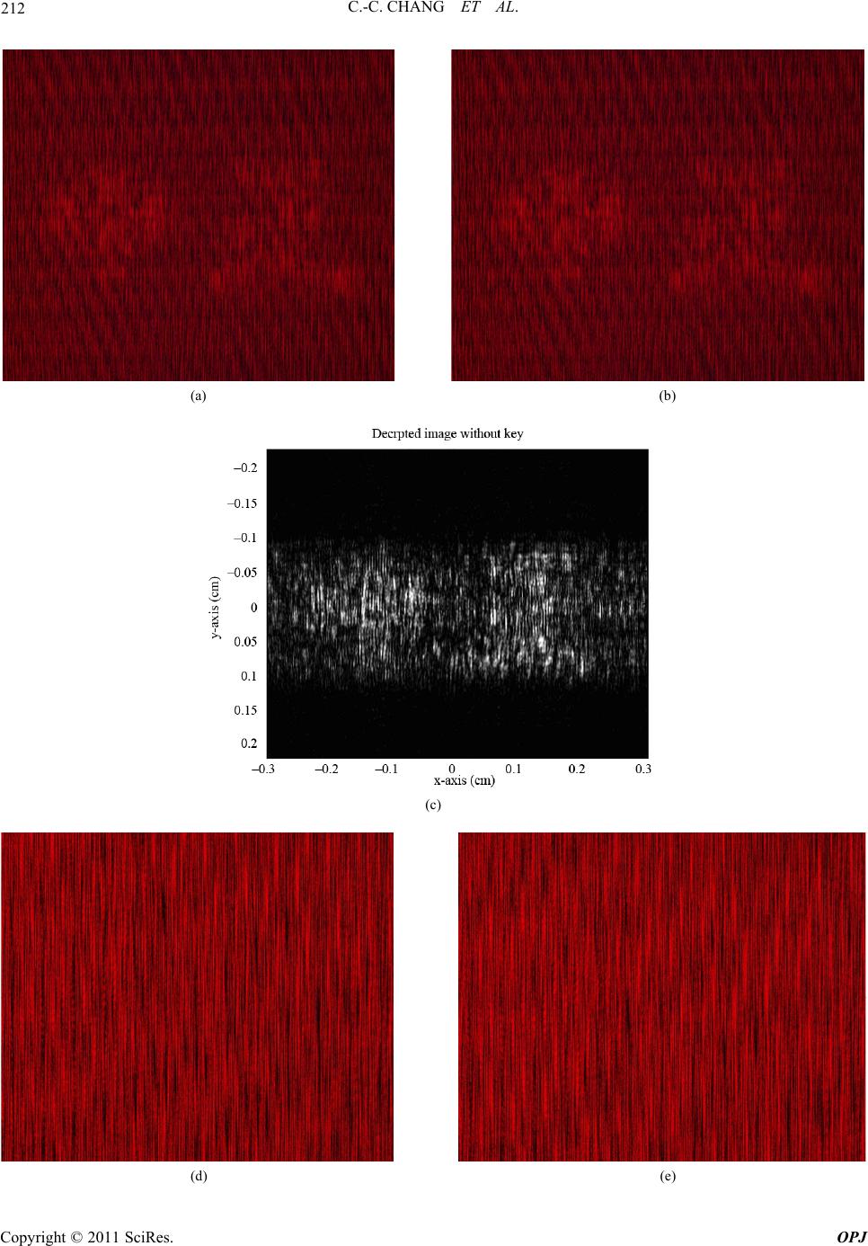 C.-C. CHANG ET AL. Copyright © 2011 SciRes. OPJ 212 (a) (b) (c) (d) (e) 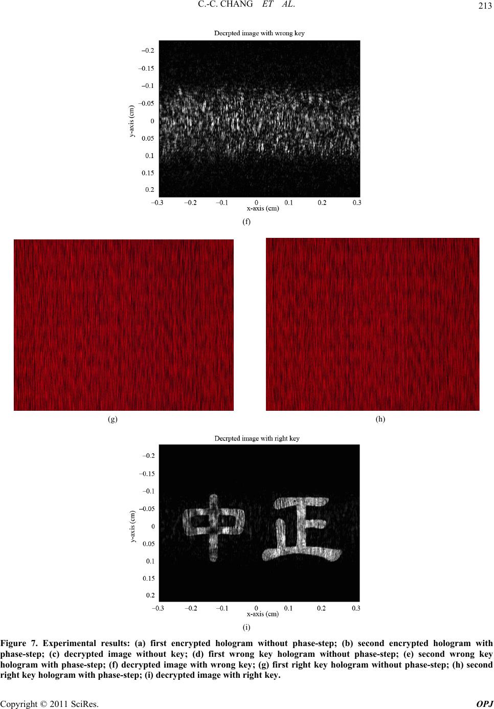 213 C.-C. CHANG ET AL. (f) (g) (h) (i) Figure 7. Experimental results: (a) first encrypted hologram without phase-step; (b) second encrypted hologram with phase-step; (c) decrypted image without key; (d) first wrong key hologram without phase-step; (e) second wrong key hologram with phase-step; (f) decrypted image with wrong key; (g) first right key hologram without phase-step; (h) second right key hologram with phase-step; (i) decrypted image with right key. Copyright © 2011 SciRes. OPJ  C.-C. CHANG ET AL. Copyright © 2011 SciRes. OPJ 214 mented using arbitrary two-step PSI with an unknown phase-step. The encrypted information that was encoded using some LPI number LLA was theoretically deter- mined to be decryptable only using the correct LPI number or the right key and cannot be recovered without a key or with an incorrect LPI number. The number of degrees of freedom in the encryption scheme increase with the distances between the object and LLA from the CCD, and also an unknown phase-step and the LPI num- ber of the LLA. Therefore, the confidential information is not easily accessible by an unauthorized person. 7. Acknowledgements The authors would like to thank the National Science Council of the Republic of China, Taiwan, for financially ting thsupporis research under Contract No. NSC 100-2221-E-451-007. . References 8 [1] J. W. Goodman and R. W. Lawrence, “Digital Image Formation from Electronically Detected Hologram,” Ap- plied Physics Letters, Vol. 11, No. 3, 1967, pp. 77-79. doi:10.1063/1.1755043 [2] U. Schnars and W. Juptner, “Direct Recording of Holo- grams by a CCD Target and Numerical Reconstruction,” Applied Optics, Vol. 33, No. 2, 1994, pp. 179-181. doi:10.1364/AO.33.000179 [3] I. Yamaguchi and T. Zhang, “Phase-Shifting Digital Holography,” Optics Letters, Vol. 22, No. 16, 1997, pp. 1268-1270. doi:10.1364/OL.22.001268 [4] B. Javidi, G. Zhang and J. tion of the Random Phase Li, “Experimental Demonstra- Encoding Technique for Image Encryption and Security Verification,” Optical Engi- neering, Vol. 35, No. 9, 1996, pp. 2506-2512. doi:10.1117/1.600854 [5] B. Javidi and T. Nomura, “Securing Information by Use of Digital Holograp 2000, pp. 28-30. hy,” Optics Letters, Vol. 25, No. 1, /OL.25.000028 doi:10.1364 , O. Matoba, S. C. Verrall and B. Javidi, formation Encryption with Phase-Shifting [6] E. Tajahuerce “Optoelectronic In Interferometry,” Applied Optics, Vol. 39, No. 14, 2000, pp. 2313-2320. doi:10.1364/AO.39.002313 [7] E. Tajahuerce and B. Javidi, “Encrypting Three-Dime sional Information with n- Digital Holography,” Applied Optics, Vol. 39, No. 35, 2000, pp. 6595-6601. doi:10.1364/AO.39.006595 [8] S. Lai and M. A. Neifeld, “Digital Wavefront R struction and Its Application econ- to Image Encryption,” Op- tics Communications, Vol. 178, No. 4-6, 2000, pp. 283- 289. doi:10.1016/S0030-4018(00)00641-6 [9] E. Tajahuerce, J. Lancis, B. Javidi and P. Andres, “Opti- cal Security and Encryption with Totally Incoherent Light,” Optics Letters, Vol. 26, No. 10, 2001, pp. 678- 680. doi:10.1364/OL.26.000678 [10] B. M. Hennelly, J. T. Sheridan, “Image Encryption and The Fractional Fourier Transform,” Optik, Vol. 114, No. 6, 2003, pp. 251-265. doi:10.1078/0030-4026-00257 [11] R. Arizaga., R. Henao, R. Torroba, “Fully Digital En- cryption Technique,” Optics Communications, Vol. 221, No. 1-3, 2003, pp. 43-47. doi:10.1016/S0030-4018(03)01462-7 [12] L. Z. Cai, M. Z. He, Q. Liu, and X. L. Yang, “Digital Image Encryption and Watermarking by Phase-Shifting Interferometry,” Applied Optics, Vol. 43, No. 15, 2004, pp. 3078-3084. doi:10.1364/AO.43.003078 [13] N. K. Nishchal, J. Joseph and K. Singh, “Fully Phase Encryption Using Digital Holography,” Optical Engi- neering, Vol. 43 No. 12, 2004, pp. 2959-2966. doi:10.1117/1.1811085 [14] T. J. Naughton and B. Javidi, “Compression of Encrypted Three-Dimensional Objects Using Digital Holography,” Optical Engineering, Vol. 43, No. 10, 2004, pp. 2233- 2238. doi:10.1117/1.1783280 [15] A. Carnicer, M. M.-Usategui, S. Arcos, and I. Juvells, p. 1644- 0.001644 “Vulnerability to Chosen-Cyphertext Attacks of Optical Encryption Schemes Based on Double Random Phase Keys,” Optics Letters, Vol. 30, No. 13, 2005, p 1646. doi:10.1364/OL.3 438 [16] L. Chen and D. Zhao, “Optical Image Encryption with Hartley Transforms,” Optics Letters, Vol. 31, No. 23, 2006, pp. 3438-3440. doi:10.1364/OL.31.003 14-1416. [17] X. F. Meng, L. Z. Cai, X. F. Xu, X. L. Yang, X. X. Shen, G. Y. Dong and Y. R. Wang, “Two-Step Phase-Shifting Interferometry and Its Application in Image Encryption,” Optics Letters, Vol. 31, No. 10, 2006, pp. 14 doi:10.1364/OL.31.001414 [18] X. Peng, H. H. Wei and P. Zhang, “Chosen-Plaintext Attack on Lensless Double-Random Phase En the Fresnel Domain,” Optics coding in Letters, Vol. 31, No. 22, 2006, pp. 3261-3263. doi:10.1364/OL.31.003261 [19] X. C. Cheng, L. Z. Cai, Y. R. Wang, X. F. Meng, H. Zhang, X. F. Xu, X. X. Shen, and G. Y. Dong, “Security Enhancement of Double-Random Phase Encryption by Amplitude Modulation,” Optics Letters, Vol. 33, No. 14, 2008, pp. 1575-1577. doi:10.1364/OL.33.001575 [20] X. F. Meng, L. H. Cai, X. F. Xu, X. L. Yang, X. X. Shen, G. Y. Dong and H. Zhang, “Full-Phase Image Encryption by Two-Step Phase-Shifting Interferometry,” Optik, Vol. 119, No. 9, 2008, pp. 434-440. doi:10.1016/j.ijleo.2007.02.003 [21] A. Nelleri, J. Joseph and K. Singh, “Lensless Complex Data Encoding for Digital Holographic Whole Informa- tion Security,” Optical E 2008, pp. 115801-115809. ngineering, Vol. 47, No. 11, /1.3028351doi:10.1117 3201-5 [22] G. L. Chen, W. K. Yang, J. C. Wang and C. C. Chang, “Deterministic Phase Encoding Encryption in Single Shot Digital Holography,” Applied Physics B, Vol. 93, No. 2-3, 2008, pp. 473-479. doi:10.1007/s00340-008- [23] Y. Zhang and B. Wang, “Optical Image Encryption  215 C.-C. CHANG ET AL. Based on Interference,” Optics Letters, Vol. 33, No. 21, 2008, pp. 2443-2445. doi:10.1364/OL.33.002443 [24] Y. L. Xiao, X. Zhou, Q. H. Wang, S. Yuan, Chen, “Optical Image E and Y. Y. ncryption Topology,” Optics Let- ters, Vol. 34, No. 20, 2009, pp. 3223-3225. doi:10.1364/OL.34.003223 [25] O. Matoba, E. Tajahuerce, E. Perez-Cabre, M. S. Millan and B. Javidi, “Optical Techniques for Information Secu- rity,” Proceedings of the IEEE, Vol. 97, No. 6, 2009, pp. 1128-1148. doi:10.1109/JPROC.2009.2018367 [26] W. T. Hsieh, M. K. Kuo, H. F. Yau and C. C. Chang, “A Simple Arbitrary Phase-Step Digital Holographic Recon- struction Approach without Blurring Using Two Holo- grams,” Optical Review, Vol. 16, No. 4, 2009, pp. 466- 471. doi:10.1007/s10043-009-0090-8 [27] R. B. Johnson and G. A. Jacobsen, “Advances in Len- . K. Yang, C. Y. Lin, H. F. Review, ticular Lens Arrays for Visual Display,” Proceedings of SPIE, Current Developments in Lens Design and Optical Engineering VI, San Diego, 2-4 August 2005, paper No. 5874-06. [28] C. C. Chang, G. L. Chen, W Yau, “Deterministic Phase Encoded Holographic Data Storage Using Lenticular Lens Array,” Optical Vol. 14, No. 4, 2007, pp. 214-218. doi:10.1007/s10043-007-0214-y [29] T. C. Poon and P. P. Banerjee, “Contemp Image Processing with MATLAB,” orary Optical Elsevier, New York, tics,” 2nd 2001, pp. 4-6. [30] “Pacur Lenstar Lenticular,” 2005. http://www.pacur.com/pdf/lenstar.pdf [31] J. W. Goodman, “Introduction to Fourier Op Edition, McGraw-Hill, Singapore, 1996, pp. 66-67. [32] Y. Takaki, H. Kawai, and H. Ohzu, “Hybrid Holographic Microscopy Free of Conjugate and Zero-Order Images,” Applied Optics, Vol. 23, No. 15, 1999, pp. 4990-4996. doi:10.1364/AO.38.004990 [33] U. Schnars and W. Juptner, “Digital Recording and Nu- merical Reconstruction of Holograms,” Measurement Science and Technology, Vol. 13, No. 9, 2002, pp. R85- R101. doi:10.1088/0957-0233/13/9/201 [34] W. K. Pratt, “Digital Image Processing,” 4th Edition, Wiley, New York, 2007, pp. 759-760. doi:10.1002/9780470097434.app3 Copyright © 2011 SciRes. OPJ
|