Computational Comparison of One Piece Metacarpo-Phalangeal/Phalangeal-Phalangeal Total Joint Replacements ()
1. Introduction
1.1. Anatomy
Trauma, osteoarthritis and rheumatoid arthritis can destroy the articulating cartilage in small and large joints, especially in metacarpo [tarso] phalangeal (MCP/MTP) and phalangeal-phalangeal (PIP) joints, which are crucial for object manipulation and interaction of the patient with the environment in contemporary society.
The palm of the hand is made of five metacarpal bones, the distal ends of which articulate with the proximal ends of the phalanges of the fingers, forming the MCP joints. The fingers contain three phalanges each: the proximal, middle and distal phalanges.
A metacarpal bone is composed of a shaft (shortened version of a long bone), with articulating surfaces at either end. The proximal end of the bone is the concave base (socket), and the distal end is the head (a convex surface, similar to a ball joint). Clinical data have shown that the transition area between the ends and the shaft is the neck to have a high incidence of fracturing.
The phalanges are composed of the same regions, with the addition of another geometric marker on the distal phalanges. The tuberosity of the bone, a bulbous protrusion at the end of the bone, allows for the connection of all soft tissue to the bone in this region.
The articulations between the proximal and middle phalanges are classified as the proximal interphalangeal joints (PIP), and the articulations between the middle and distal phalanges are classified as the distal interphalangeal joints (DIP). The MCP and MTP joints are similar in structure and function.
The digits of the hand are stabilized primarily by the digital collateral ligaments, on the dorsal side of the fingers. Each MCP has a fibrocartilaginous plate on the palmar side, called the palmar plate, which is attached to the proximal phalange by checkrein ligaments at the neck of the bone, and to the metacarpal more loosely. A tendon sheath contains tendons at the joints, allowing for the tendons to act as pulleys. These sheaths, fibrous digital sheaths, are attached to the palmar plates at each joint, and to form tunnels for the flexor muscles.
The main motion of the joints is flexion and extension, with limits on the range of these movements, controlled by two major muscle groups of the same name, flexors and extensors [1] -[8] . Abduction-adduction is the second main volitional motion of the MCP.
Additionally, there is substantial accessory motion that occurs. When the MCP is relaxed, the joint can be distracted compressed, translated anterioposteriorly and medial-laterally and axially rotated. As with the arches of the hand, these accessory motions are used to better manipulate objects. The more ulnar MCP joints (4, 5 digits) are able to be rotated and can undergo more flexion-extension. Table 1 shows the range of motion.
The range of motion for the DIP and PIP joints is different from this, with no adduction-abduction available in a normal range of biomechanics. Table 2 shows the range of motion for these joints.
Under external loaded conditions of 1 N from an external source, the joint forces on the MCP joint have been found to range from 5 N to 24 N [9] . The position of the phalange in relation to the metacarpal bone has some effect on the force. At 0˚ flexion (finger pointing) the force on the MCP is 14 N and at 45˚ flexion the force has increased to 17.5 N [10] [11] .
1.2. Joint Damage
In the United States, 80% of all amputations are due to inadequately treated fractures, which is approximately

Table 1. The overall range of motion for the index and little finger MCP joints (F-E: flexion extension; A-A: abductionadduction).
Table 2. The range of motion for DIP and PIP joints of the digits.
57,000 amputations per year. Of these, approximately 25% involve the toe or finger (US Population Incidnence Rates per 100,000 [1996]) [12] . For surfaces that are fractured, the healing of the bone results in uneven surfaces that are not smooth when compared with the original. These uneven surfaces may result in pain, restricted motion and migration of tendons leading to deformities.
A common condition that may result from the total destruction of articulating cartilage, resulting in the contact between the two articulating surfaces of the bones is osteoarthrosis is a degenerative, chronic, non-inflammatory disease due to the total destruction of articulating cartilage and the resulting contact between the two bone surfaces wearing against each other. Degenerative joint disease (osteoarthritis) is the deterioration of the hyaline articulating cartilage, a dense collagen matrix that prevents loss of both functionality and material, of synovial joints in addition to the condyles of the bones in the joint. It degrades the integrity and composition of the cartilage [5] [9] .
Arthritis, most notably rheumatoid arthritis, can destroy the surfaces of the bones and may completely compromise the articular cartilage of the joint surface [13] . These conditions remove the smooth surface of the bone as the force is applied to the joint surface. This results in the smooth surface of the joints being destroyed by repetition of the applied force from movement. As the surface heals, the joint surface is no longer slickly smooth; instead there are ridges and bumps that cause painful motion. Not only does motion become painful and difficult for the joint, it also causes physical disfigurement and pain without motion. This condition affects not only the bones and their articulating surfaces, but also the connective and stabilizing tissue that crosses joint.
Rheumatoid arthritis often causes distortion of the MCP joints in patients, with presentations of ulnar drift, Swan-neck deformity, boutonniere deformity and palmar dislocation of the MCP joint. This condition also causes the reduction of the tensile strength of the connective tissue of the articulating joints. With the degradation of the connective tendons, the joints begin to permanently degrade or deform are worn away. The palmar dislocation of the MCP joint affects the flexion of the fingers during gripping. During this motion, the flexor digitorum superficialis and profundus deflect towards the palmar region of the MCP, causing a bowstring force to develop, which places the collateral ligaments in tension. In a normal hand, the force associated with this transfers from the flexor to the palmar plate, then to the collateral ligaments and finally to the posterior tubercle of the metacarpal head. In arthritic patients, the elasticity and strength of the supporting tissues is compromised due to constant force being applied to the collateral ligaments, which may resulting in rupturing and eventual migration of the phalanges towards the metacarpal bone, resulting in total dislocation of the MCP.
Even in normal, healthy hands there are factors of ulnar deviation in the posture of the rays, due to gravity, asymmetrics of the joints, patient-specific trends in the pull of the extrinisic flexor tendons passing over the MCP, and most importantly, from the every-day usage of the hand, especially large gripping forces between the digits and the thumb. The drifting of the MCP joints is again due to the bowstring forces present on the MCP due to deflection of the extensor digitorum tendons, which does not occur in healthy hands due to the collateral ligaments (radial, mainly) and dorsal hood maintaining the location of the tendon anterior to the joint. In severe cases of rheumatoid arthritis, the radial transverse fibers of the dorsal hood are damaged, ruptured or stretched, which causes the tendon to slip to the ulnar side of the joint, pulling on the MCP. The deviation of the joint is caused by the moment arm generated by the location of the tendon relative to the bone, which enters into a positive feedback system: as the ulnar deviation increases, the moment arm increases which then increases the ulnar deviation, and may eventually result of rupturing the collateral ligaments, leading to total joint dislocation [13] -[20] .
1.3. Treatments
Total joint replacement is the ideal treatment for permanent joint damage in the hands. Surface arthroplasty designs can restore functionality, reduce pain and correct aesthetic issues, with problems on contemporary designs including decreased stability, increased range of motion, and fixation failures in vivo.
While the most popular implants are the soft, elastomeric one piece designs, there are many issues with such implants that make them undesirable. By comparison, surface arthroplasty methods offer several distinct advantages: matching material properties, joint functionality restoration after implantation and pain management equivalent to that of the soft implants. Despite these advantages, there are problems that need to be addressed with these designs, especially in the failure mechanisms compared between designs, which to our knowledge have only been examined in explanted analysis and clinical follow up studies. The analysis of failure mechanisms in contemporary designs is of use in determining both limitations in the devices as well as possible avenues for further improvement in TJR designs [13] -[20] .
2. Methods and Materials
2.1. Geometry Modeling
Simplified analysis comparing the one piece analysis with a standard representing a natural, healthy joint and the surface arthroplasty designs laterally and posteriorly. Superposition was used to take the summation of various forces exerted by different structures in order to generate a model that made use of the main movements of the joint rather than individual muscles.
From a literature survey, a Swanson based geometry, a NeuFlex based geometry and a Sutter approximation (Avanta) shown by Meroli were selected for examination.
Specific geometries were made from sizes given for individual parts where available, photographic comparisons between devices and were scaled to the natural geometry used as a standard. The developed models are shown in Figure 1.
Material selection was done on the basis of specifications for each design: ultrahigh molecular weight polyethylene (UHMWPE), pyrolytic carbon, titanium alloy, and cobalt alloy.
Mechanical properties were assigned based upon standard values from literature for orthopedic implant materials, and were taken as standard to the solid model library when not specified as different.
2.2. Computational Analysis
Solidworks and ANSYS solid modelers were used to check the results found via numerical analysis, and to further examine the failure mechanisms of the joints under two loading conditions: a flexing load applied perpendicular to the length of the implant and medial-lateral displacement loading that created a three point bending scenario. Loading of 50 N was used as the initial comparison between geometries to determine the stress concentrating regions and behaviors. This load was correlated with forces experienced on the joint due to small loads on the surface of the finger (~5 N external loads). Failure of the simulations due to large scale displacements (on the order to centimeters) forced loads of 10 N to be used when necessary.
The behavior of the natural standard was compared to clinical data for failure to determine the approximations accuracy and viability as a model. Crucial failure locations are at the interface between the diaphysis and the epiphysis of the bone and at the interface between the edges of the articulating surfaces. Fixation of the model created stress concentrator regions at the proximal surface of the bone (fixed surface), which were taken as interference in the model and otherwise ignored.
The same scenarios were used for the examined geometries.
Based upon anatomical data, such as the range of motion and the types of motion on the joints, flexion loading and medial-lateral loading were selected. Due to a lack of fixation of the prostheses at the implant site, the models are considered initially unflexed.
3. Results
3.1. Geometric Modeling
Two dimensional comparisons were made of a natural joint, a one piece implant, and surface arthroplasty implants to compare basic behavior, force distribution and contributions to the models.
Basic mechanical analysis of the devices was done to correlate with the computational models. All examination was done in the elastic region of the material, to simplify the analysis. General deformation and stress were calculated for each model.
Based upon surgical procedure and comparison between a natural joint and an implanted single piece implant, the frictional force between implant and the bone holds the device stationary. Numerical analysis of the implants shows that, assuming an isotropic material, that the center of the joint will be an area of stress concentration.
3.2. Flexion Loading
Computational modeling of the flexion loads, shown in Figure 2, showed that the single piece implant has stress concentrations in the arm with the applied flexion load and the center of the joint. The fixed arm had no mea-
 (a)
(a) (b)
(b) (c)
(c)
Figure 1. The geometries of the (a) Avanta (Sutter), (b) NeuFlex, (c) Swanson representative geometries, assembled in Solidworks and exported as solid meshes to ANSYS mechanical analysis. The dimensions used for developing the models were the same as those for the numerical analysis.

Figure 2. The computational stress concentrations across the models, under flexion extension simulated loading at 10 N of force. The stress concentrations for the Swanson are seen at the interface of the distal arm and the flexion center, with no large concentrations found in the center or other regions of the joint. The Sutter device had stress along the entire proximal arm, and at the flexion center of the joint, on both the palmar and dorsal aspects. The NeuFlex device had stress concentrations at the fixation point on the proximal arm, similar to the Sutter, and slight concentrations seen at the flexion center of the joint.
surable stress in it. The NeuFlex implant had stress concentrations in the arm with the applied load, and some at the vertex of the center. The Swanson implant had no stress in the center of the joint, with all measurable stress occurring at the interface between the arm with the applied stress and center of the joint.
3.3. Medial-Lateral Loading
Medial-lateral loading, shown in Figure 3, for the single piece implant showed stress concentrations in the center of the joint, at the interfaces arms with the center and along the arms. The joint deformed along the arm proximal to the fixed end, with highest concentrations of stress at the fixed end and along the arm. The NeuFlex had measurable stress only at the vertex of the joint center, with no deformation or rotation of the joint during loading. The stress extended at the same magnitude along the entire vertex. The Swanson representative had stress concentrations at the transition between the thin and thickening portions of the implant arms, and at the interface between the arms and the joint center.
4. Discussion
The computational analysis of the joints indicates that stress concentrations are at the interfaces between the arms and the joint centers, as well as at the flexion centers of the Neuflex and Sutter approximation. Table 3 shows the peak stress values for each geometry, all of which occurred in the flexion-extension loading. The maximum stress forces were more than an order of magnitude higher for each geometry in flexion-extension than for the medial lateral loading. The stress concentrators seen at proximal to the ends of the arms are due to interference from constraining the model, in order to simulate conditions. In actuality, these implants are not fixed, thus allowing for greater motion at the implant site which makes these procedures essentially useful for pain management and aesthetics. However, clinical data has shown that the failure of the Swanson implant, the most popular of the three examined, fails at the interface between the arms and joint center, as shown here.
This may be due to the design of the joint not allowing for proper flexion of the joint center when implanted; instead the arms of the joint move from the implant channels and flex under loading, generating stress concentrators at the center. Additionally, as these implants are not restrained in the joint, loading from the top of the


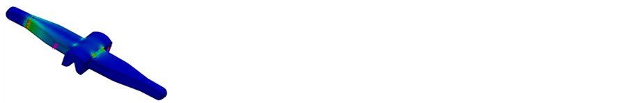
Figure 3. The The stress contour plots for the three geometries under medial-lateral loading. Dark blue shows minimal stress, with the lighter colored areas showing higher stress concentrations. The proximal end of each implant was fixed for these simulations.
Table 3. The peak stress values found for the simulations, under a 50 N load. Peak values were recorded for flexion-extension simulations as being more than an order of magnitude greater than those for the medial-lateral loading scheme.
joint would generate a shear force, as shown in the medial-lateral loading, that would cause implant failure. Joyce found that failure at the interface occurs for both the Sutter and the Swanson in a study of explanted devices. Continuous loading in these manners is the most likely cause of failure in the joints over time, which explains failure rates of approximately two thirds [16] [17] [19] -[21] .
5. Conclusions
In recent years, single piece elastomeric implants have taken control of the market for finger prostheses, with some European studies showing as many as 98% of all procedures being done with soft material single piece implants. The determination of the cause of failure in such joints is necessary to improve upon products that may impact a large portion of the population. As of now, there is still no available joint that restores aesthetics and functionality while managing pain.
There is currently some debate among researchers as to whether the inclusion of gromets with the Swanson implant improves the behavior of the joint. Further examination of this is required. Also, other loading mechanisms could be examined to ascertain other, if any, causes of catastrophic failure in finger prostheses. Clincal data reported in literature have found that the Sutter (Avanta) implant shows significant failure at the interface between the implant arm and flexion center, the same as presented in our study. Not only does this validate our model, but it also shows that the main mechanism for failure is the flexion/extension motion that is inherent in all finger joints. The abduction/adduction motion of the joint does not seem to provide the main loading on the joint. Since all finger joint replacement procedures will provide restoration of this motion to the patient, this failure mechanism will occur in most joints until changes are made to the design or material. It can be assumed that this would be the same for the other examined joints as well. Finally, there are many other commercially available single piece implants, those examined within where were found from a literature to be the most widespread with clinical relevance.
Acknowledgements
The authors would like to thank Mercer University and the School of Engineering for providing the resources and funding for this pursuit.
Abbreviations
metacar-Pophalangeal—MCP metatarso-Phalangeal—MTP proximal interphalangeal—PIP distal interphalangeal—DIP Flexion extension motion—F-E abduction adduction motion—A-A