1. Introduction
Emplacement of dykes is a very complex hydro and thermodynamic process. There exists a wide variety of research papers on this subject where a lot of data are published. The process when the local density difference controls the height of magma ascent is investigated in [1]. They find that the magma can reach few kilometres above neutral buoyancy level. [2] published data for two kimberlite dyke swarms. They find average thick-nesses of the dykes to be 0.64 and 0.40 meters respectively, with variations of the same order of magnitude. In [3], Gudmundsson discusses the formation of dykes in Iceland and concludes that the minimum tensile strength makes them intrude the subvertical joints in lava flows but only 1% - 2% reach the surface. In [4] are observations of dykes width in three intra-plate volcanoes and it is found to increase linearly as a function of distance from the volcanic centre. This is explained by decreasing intrusion frequency.
The dyke emplacement is a process controlled by the stresses and strains in the host rock and this is the subject of numerous papers. In [5] the magma flow in a crack is modelled, producing many interesting results such as the equilibrium width dyke where the flow resistance at the walls is exactly balanced by the buoyancy of the warm magma. The influence of the viscosity is clearly stated in [6]. According to [7], the fracture resistance of the elastic medium can be neglected, and this is followed here, and they furthermore show that the propagation of the fracture is limited by the viscosity of the magma. Professor Walker has written numerous papers on the geology of Iceland, especially the eastern county. Of his numerous papers, only [8] is listed here.
The following treatment is based on the translatory wave theory. It is a fluid flow theory, specially constructed for isolated flow disturbances. It is therefore very suitable for flows penetrating an unusual environment like floods running over dry land [9], density driven gravity waves [10] and tsunamis [11]; it has not been used before on the dyke emplacement problem.
2. Lithostatic Considerations
In a rock formation overlaying a magma chamber or a sill, the stress situation can be described as Figure 1(a). The vertical stress, considered here as the largest principal stress, is the weight of the overburden (rh the density
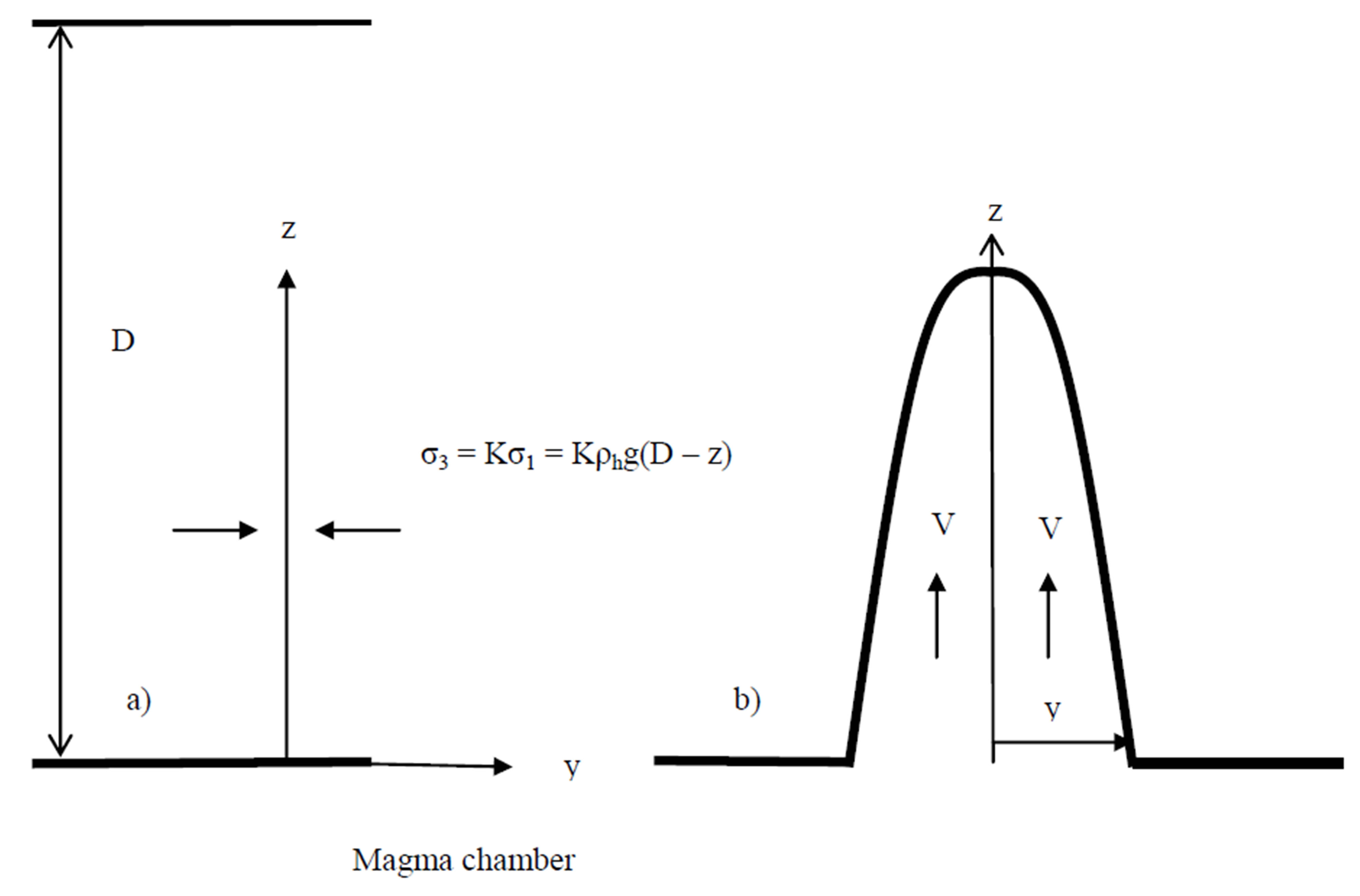
Figure 1. (a) Before onset of intrusion formation; (b) The intrusion process.
of the host rock) and the smaller lateral principal stress is proportional to it with an unknown proportionality factor K. In a formation in a positive strain situation (elongation) we will have Ka < K < Ko where index “a” refers to active stress, but “o” to neutral stress (no strain) situation. In a negative strain situation (compression) we will have Ko < K < Kp where index “p” refers to passive stress.
The onset of a dyke intrusion may be due to several reasons, all beyond the scope of this paper. The dyke originates from the magma chamber (or the sill), it is supposed to supply fluid magma to the dyke without significant pressure changes at the source. When in progress, the intrusion will let hydrostatic magma pressure of the order of magnitude s1 = rhgD into a fracture that progresses upwards.
As s1 > s2 the stress difference will push the walls of the fracture outward to a distance y from the original position (Figure 1(b)). The displacement of the walls will evoke a reaction stress sr = Sy where S is a stiffness coefficient. As long as y is small and transient pressure changes or permanent (plastic) deformation of the host rock has not taken place, the deformation is elastic and S is independent of y.
3. Fluid Dynamics of an Intrusion
Pressure and shear can be supposed to dominate acceleration forces in the migration of the intrusion upwards. Here the intrusion is supposed to migrate like a translatory wave with constant celerity up the fracture in the host rock.
In Figure 1 the static pressure p(z) (corresponding to V = 0) in the intrusion can be assumed somewhat higher than the horizontal stress, or
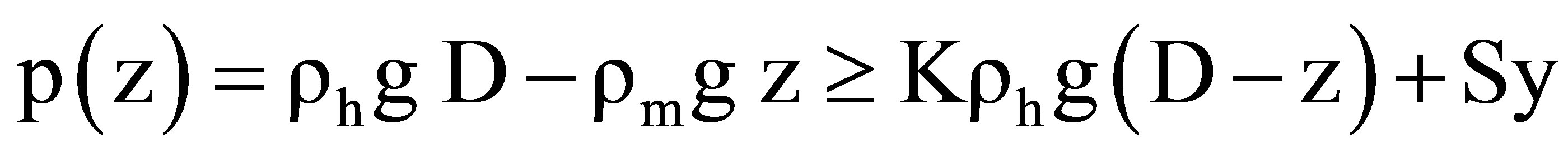 . The difference is due to the pressure gradient in the flow. The magma is a very viscous substance so when V > 0 (Figure 1(b)) we will have:
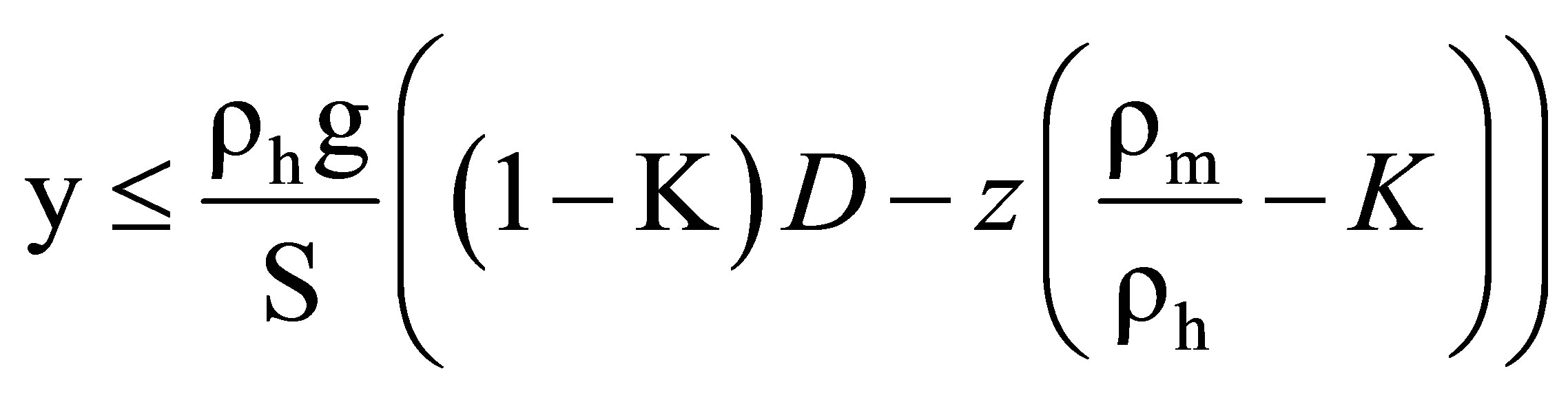 (1)
(1)
The equal sign is valid in the no flow (V = 0) situation.  is most likely positive as the density ratio is only slightly different from one, so for constant S, the intrusion width will decrease upwards. Variable S will be considered later.
The wave form progresses with more or less constant form and velocity V (Figure 1(b)), so the velocity of the fluid will also be V. Then the cross-section integrated continuity equation:
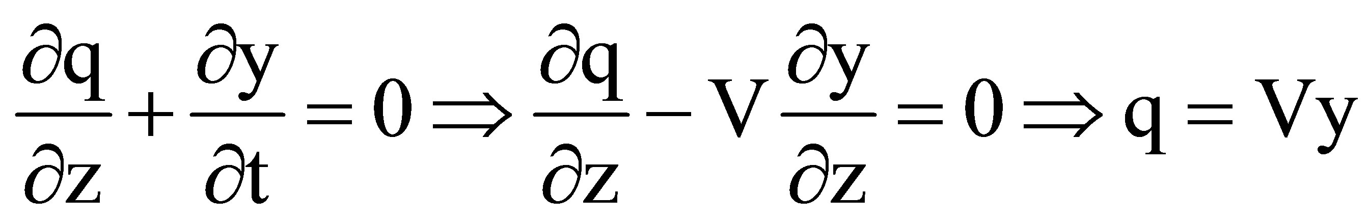
allows the solution:
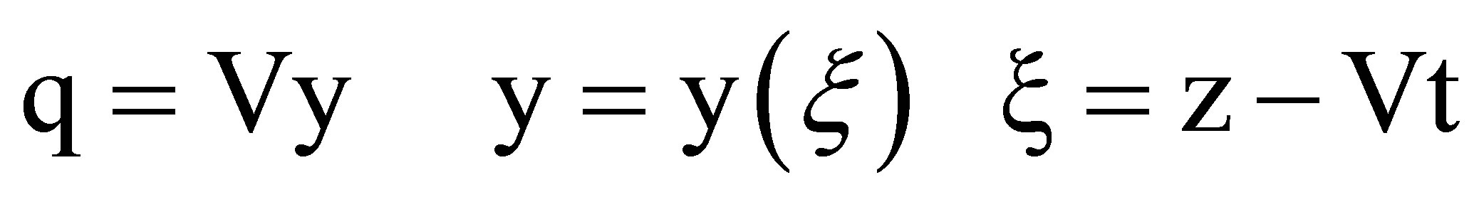 (2)
(2)
The continuity equation for the flow will then be automatically fulfilled when V is constant. Momentum loss is caused by the friction against the walls.
When the lateral pressure in the host rock and in the flowing magma is assumed equal the momentum equation becomes.
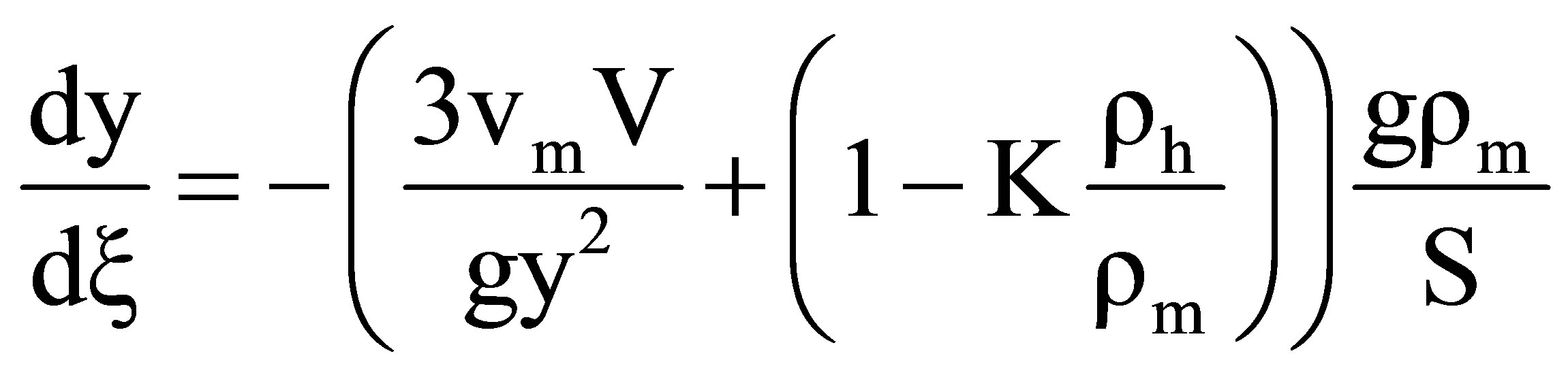 (3)
(3)
This equation integrates to the static value of y (equal sign in Equation (1)) in the case V = 0. For V positive, the equation can also be integrated. Defining following constants
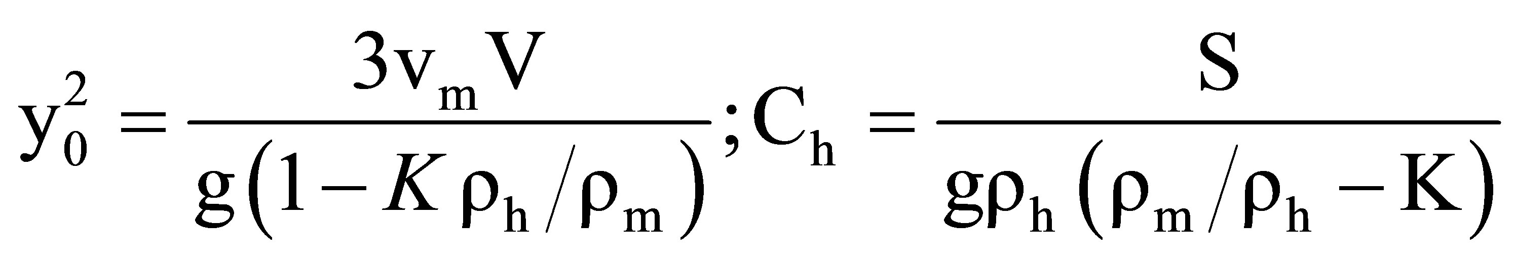 (4)
(4)
We call y0 the width scale and Ch the composite stiffness of the host rock.
Integrating Equation (3) we obtain
 (5)
(5)
The function Equation (5) has very different properties for y/y0 large and small respectively. It should be noted that x takes only negative values in z < D as z = Vt is the top of the intrusion. In applying limits to Equation (5) it must be noted that p(z) cannot exceed the static value and this sets a limit on y, ymax that has to be deducted from Equation (1) (equal sign). When this happens the flow can become buoyant and Equation (5) will no longer be valid. If the flow continues, ymax progresses upwards with V and for the flow below the value of z where the constant width starts, the equations in [5] for buoyant magma flows will be valid.
We have considered S to be a constant, that is necessary to do, but only piecewise. If S changes when the dyke breaks from one rock layer into another with different S, the width scale and the composite stiffness will change, but after a small intermediate z-distance the process will adapt to the new values. E.g. when S diminishes the width scale and the composite stiffness will go down and the dyke widens upwards. If it stops a little later, we may have the well-known teardrop shaped intrusions [12].
4. Limiting Values and Estimations of Parameters
4.1. Dyke Dimensions
At the level z = 0 the pressure is the lithostatic pressure in all directions as the magma is liquid. This sets the maximum value y can take as the biggest possible halfwidth of the intrusion, it will be in z = 0. Naming it W/2 we will have:
 (6)
(6)
When Equation (5) reaches this value in z = 0 at time t, the dyke is L = Vt high up in the host rock. Inserting Equation (6) in Equation (5) and evaluating gives,
 (7)
(7)
The relative density difference (rh – rm)/rh is called D. There is nothing in the fluid mechanics to stop the dyke from penetrating the surface, so Equation (7) may be evaluated for L = D. This gives.
 (8)
(8)
As D/(1–K) is a small number, ymax > y0. When the right side of Equation (8) is known, finding y0 is not a problem. For ymax/y0 > 3 - 5, inserting arctan(ymax/y0) = p/2 will give sufficiently accurate results for ymax/y0. Then y0 is found and from it the velocity V by using the definition of the dyke width scale.
4.2. Composite Stiffness
The liquid magma seeks out cracks and other weaknesses in the host rock, there are enough of them. In a crack or a fault there is no tensile strength, any pressure above the lithostatic will cause them to yield. Properties for igneous rocks do therefore not apply; this is clearly stated in [5].
The elastic deformation of the dyke’s wall’s follows Hook’s law. The total deformation is y, the length of influence where this deformation is taken up by the rock is L, say, then S = E/L. The most likely measurements available to estimate seem to the storage coefficients inferred from short time pumping tests into 2 - 3 km deep confined aquifers as there is direct linear relationship between the storage coefficient and E. Sandstones and unconsolidated lava rocks usually have E of the order of magnitude 10 GPa. L is estimated equal to the depth to the magma, which in this case will be set to 3 km as the pumping tests wells reach this maximum depth. This yields S = 3.3 MPa/m The analogy between water and magma injection may seem farfetched, but in the short term this is the same displacement process. In the long term however there is a large difference. When pumping a water slug into an aquifer, we will have elastic deformation just around the injection point and a sudden rise in the pressure. When time goes the water in the slug will percolate away and the pressure differences evened out in transient pressure variations. The magma cannot do this. But the strain it creates may very well undergo transient changes because of fluid flow in the rock. This contributes to regenerating the pressure field by spreading the pressure disturbance of the dyke to a larger area after the dyke has frozen in place.
The K factor is somewhere between 0, 3 and 1. The estimate K = 0.6 is used. This gives us the dimensionless composite stiffness:
Ch = 128
4.3. Upwards Dyke Slope
Equation (5) gives = 0 in y = 0 (i.e. z = Vt). As may be seen from Equations (4) and (5), the dy/dz becomes negative small for large y, so the dykes walls will slope gently together in the upwards direction. The arctan function never becomes larger than p/2, and in that limit we will have a slope:
IDyke = 1/Ch (9)
This according to the previously estimated Ch value is of the order 1 meter for each 100 meters in elevation difference. This is not easy to observe in the field, local weaknesses in the host rock make the dyke walls depart from a straight line, and high vertical walls with dykes accessible for measurements are uncommon. Besides, if S changes to a lower value the width may increase upwards locally.
4.4. Viscosity and Density
Viscosity of a flowing basalt intrusion is very difficult to estimate. The magma must be assumed to cool down on its way up. When crystalization begins the flow can stop suddenly if the critical shear stress (yield stress) rises above the shear stress of the flow at the wall. From data in [6] pp. 607-608 the viscosity values in Table 1 are derived.
To make an intrusion the dyke has to penetrate the regions of ductile and brittle rock in order to reach the host rock. In these layers the viscosity is very high. The viscosity of the magma that reaches host rock with the properties of Equation (1) in [6] is therefore very difficult to predict. In the following the values n = 0.4 m2/s, density rm = 2600 kg/m3 and rh 100 kg/m3 higher, will be used as an example.
4.5. Width Scale and Velocity
Using Equations (4), (6) and (8), the example values and limiting rules obtained, following values are deductedymax = 9.7 m y0 = 0.57 m V = 1.0 m As may be seen the magma flows very fast even at this high viscosity, which belongs to the range where the viscosity is very temperature sensitive. This supports the conclusion reach by many earth scientists, that the intrusion process is mainly governed by the magma viscosity which is very temperature dependent.
5. Variations in the Parameters
5.1. Variable Stiffness
If the stiffness decreases upwards, the flow will at some point go from one formation with value S1, to another with value S2 < S1. As the pressure does not change across the boundary line and the flow Vy is constant too, we will have:
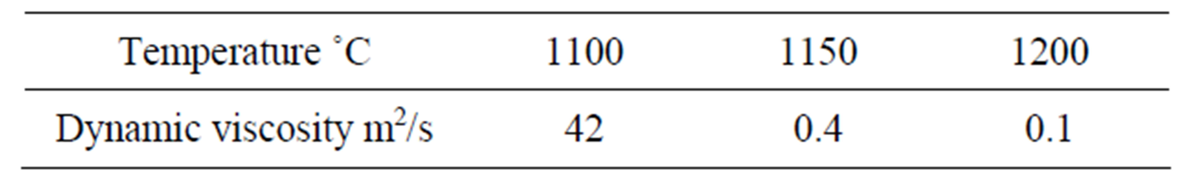
Table 1. Viscosity of basalt magma.
y2 = y1S1/S2, V2 = V1S2/S1
The width goes up and the velocity goes down. There will be an elevation range between level 1 and level 2 where the flow adapts to the new environment and in this range Equation (5) does not apply. The length of this range may be estimated of the order of magnitude ~ ymax.
5.2. Variations in Lithostatic Pressure
An intrusion of a dyke changes the strain rate of the host rock and therefore the lithostatic pressure. This increases the K value temporarily to almost 1 so new intrusion will have smaller thickness. When the dyke width scale gets too small the intrusion activity can nothing but stop, but field investigations show that intrusions just few centimeter thick do exist. If the example parameters previously estimated are used, he K value would have to be around 0.99 for so narrow dykes to be formed.
Equation (1) tells us that when a dyke freezes in place, the ratio K = s3/s1 becomes very close to 1 in the vicinity of the new dyke. This will happen in an area of influence that in the first approximation can be viewed as a circle with radius R of the order of magnitude long, as the length of the dyke, see Figure 2 in [5] and discussion. Further away the pressure disturbance from the emplacement of the dyke will diminish as 1/R for a big dike, but as 1/R2 for a small one. This is the initial stress-increase disturbance in the host rock; later this disturbance will diminish with time due to transient pressure changes from fluid flow (upper layers) or local plastic deformations.
This is particularly interesting in rift zones like Iceland where the plates are diverging with 1 or 2 centimeters/y. Such a deformation would mean a stress reduction of 0.5 KPa in a host rock of the previously estimated elasticity (10 GPa) in a 30 - 40 km wide rift zone. This is not a large annual pressure change, but would mean a regeneration of a K increased to a value around 1, back to about 0.6 in 40 - 50 years. Counting the transient pressure changes too, the regeneration of the K value could be a lot quicker. No further conclusions can be drawn at the present stage of research, however.
6. Dykes That Freeze in Place
When the dyke cools down and the flows stop it must be assumed to happen first at the top. If the top does stop, the flow will not stop immediately but keep going until it has widened the intrusion up to the static (V = 0 or the
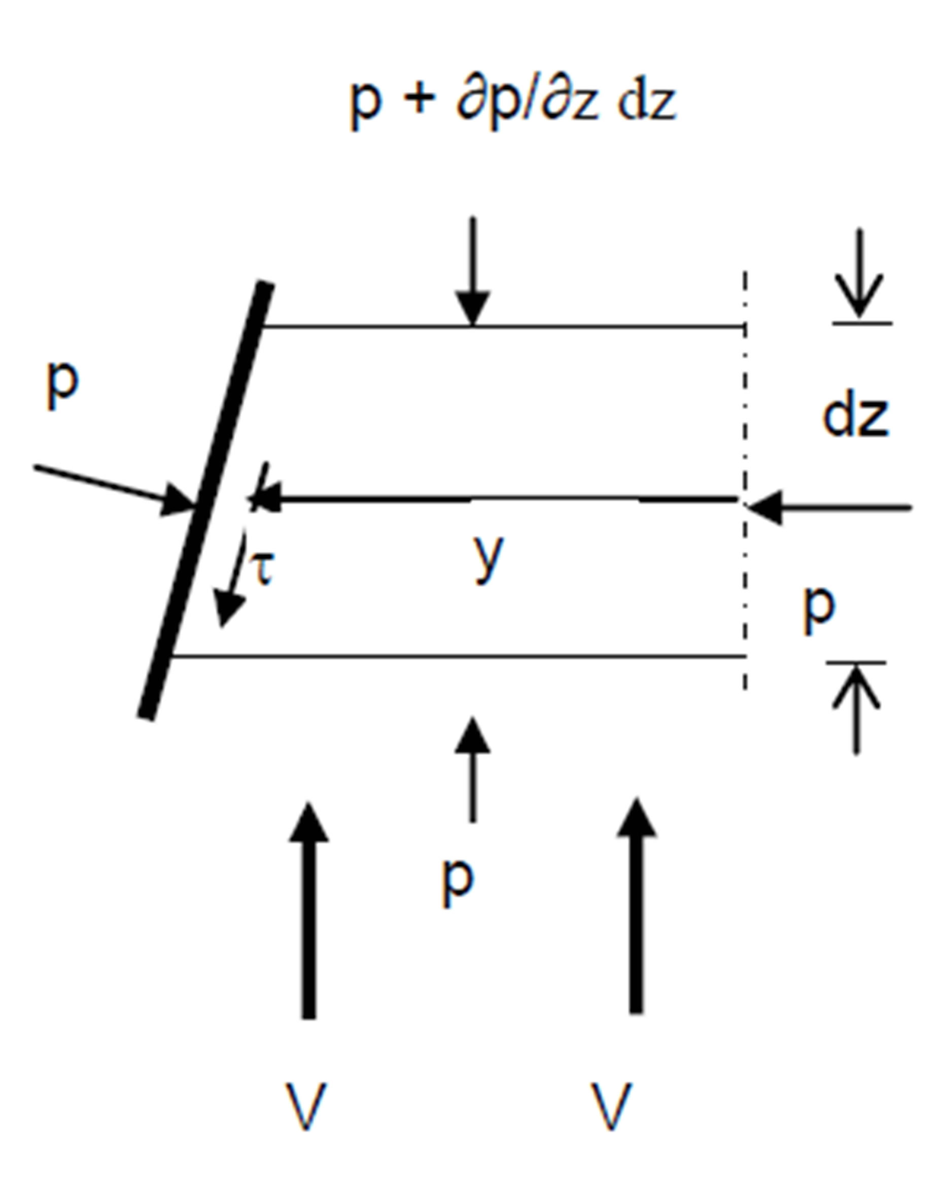
Figure 2. Force balance in the magma flow.
equal sign in Equation (1)) value. Calculating the slope of the walls in that situation, we find the exactly same value as Equation (6). This equation is produced by assuming Arctan (ymax/y0) ≈ p/2. This means that the form of the dyke is already very close to the static form in most of its height, so very little flow is needed to widen the intrusion. The dyke will, for all practical purposes freeze in place, if just the head is stopped. If the dykes head hits a water on its way up that stops it, the entire dyke stops. The magma flow cannot widen the fissure and get past the plug.
7. Comparing Dyke Data
Measuring dyke thicknesses and frequency is standard practice in geological investigations of dyke swarms. If thickness of the same dyke is measured in different elevations the composite stiffness (Ch value) of the host rock can be calculated and the S estimated. Varying thicknesses will give information on the K value.
As an example Figure 3 shows a dyke flow from formation 1 to formation 2. In the basalt formations of in east Iceland there is a number of dyke swarms. The geology has been adequately described by Prof. G. P. L. Walker in a series of papers, see [8]. In Table 2 there is an investigation of the Berufjördur complex provided by Magnus Olafsson [13].
It is very uncertain if the increase in dyke thickness from series B to series C is significant. There are 96 dykes in the B series but only 32 in the C series about 500 meters higher up. Of the 96 there are 69 accessible in the A series and if the change in average thickness from A to B is deemed significant, this would indicate a 15% decrease in the stiffness S and the velocity from layer 1 (Figure 1) to layer 2.
8. Conclusions
The translator wave theory works very well for the dyke emplacement process. The stress balance between the host rock and the flowing magma is very delicate and very difficult to handle except assuming a piecewise lin-
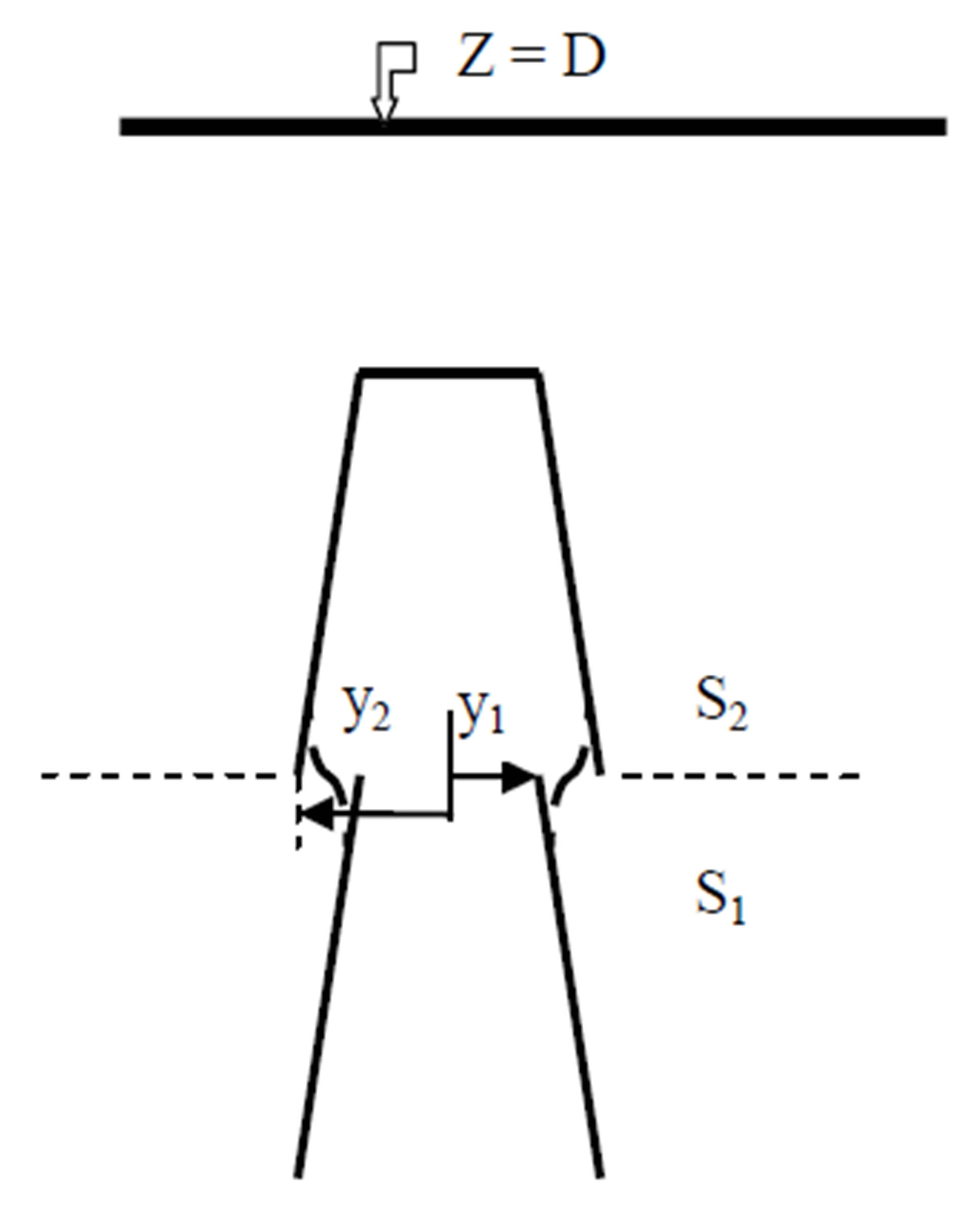
Figure 3. Change of stiffness from S1 > S2.
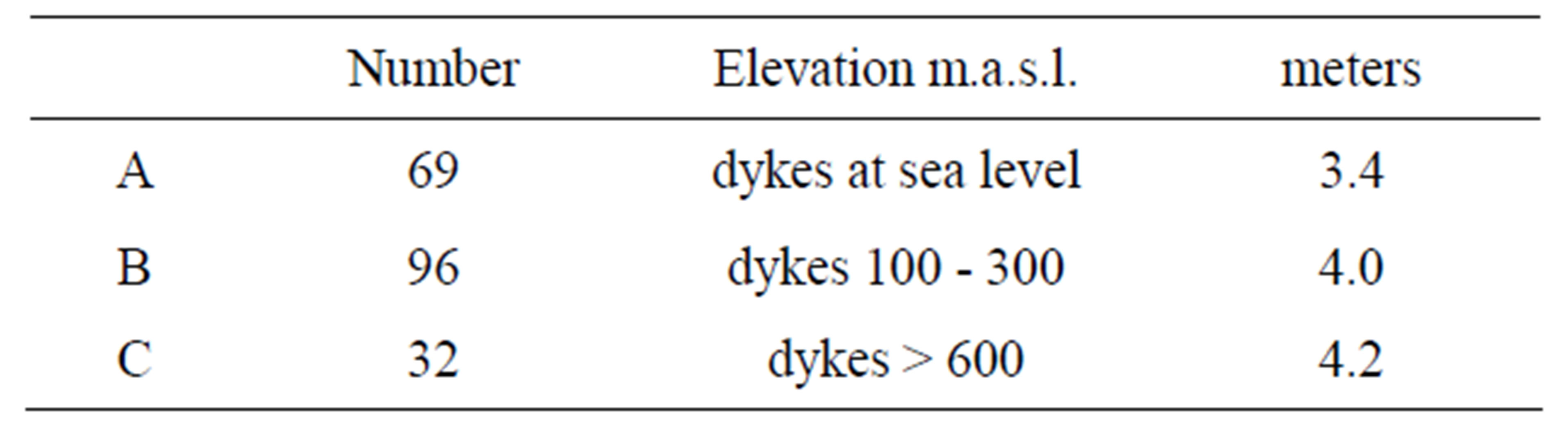
Table 2. Average dyke thickness in the Berufjördur complex.
ear relationship between stresses and strain and most researchers do that.
The result of the analysis produces the rather difficult looking Equation (5) for the development of the form of the dyke with time. A closer evaluation shows that the arctangent function can be replaced by its maximum value in most of the dyke’s length and has only to be considered in the immediate neighborhood of the head penetrating into the host rock.
Two main parameters control the flow, y0 the width scale and Ch the composite stiffness of the host rock. They represent the properties of the host rock and the magma, such as elasticity and viscosity.
The theory explains interesting features, known from geological investigations, such as:
1) Dykes have an almost constant thickness, but very variable from dyke to dyke.
2) Viscosity is a very dominating factor.
3) Dykes can widen upwards (teardrop shape).
4) Dykes can freeze in place.
The explanations to these features are following:
1) In a host rock of constant elasticity upwards slope is very small, order of 1%.
2) Higher viscosity increases y0 and the stress situation does not allow that.
3) Local width of dyke increases suddenly if the dyke runs into lower elasticity.
4. Width of dyke is very close to the static maximum, the dykes freeze in place if the head stops, e.g. due to cooling.
Following additions that appear to be new are suggested:
The dyke can penetrate the host rock with constant velocity from bottom to top if the width scale and the composite stiffness of the rock stay constant.
Ch, the composite stiffness of the host rock, is the inclination of the dyke walls. If the inclination can be successfully observed, this important parameter can be observed in the field.