Optimum Distribution of Two Different Phase Change Materials between Various Components of Roof Air-Conditioned Room, Suitable to Reduce Annual Energy Consumption ()
1. Introduction
Recently, modern lifestyle leads to a huge problem of energy consumption worldwide. Especially, the excessive climatic conditions produce discomfort situation, which requires frequently using air conditioning systems, subsequently results in increasing of domestic energy consumption. Hence, this involves an increasing interest in thermal correction of building designs to create comfort situations. In order to save this energy exhaustion, among best known solutions proposed are: Use insulated walls/ roofs in building [1], use of reflective color outdoor surfaces [2] and use of energy storage devices in the building structure [3]. As it is predicted in the literature, the mismatch that is often found between the supply and demand of energy can be corrected by these systems which provide a valuable solution. This is concerned against waste energy by storing and to restore it after, which are as important as developing new sources of energy. Hence the thermal energy storage systems such as phase change materials (PCMs) provide the potential to attain energy savings, which in turn reduce the environment problems due to conventional energy use.
Currently, the research about use of the phase change material (PCM) was increasingly under consideration especially for latent heat accumulator [4,5], solar heating system [6], building energy conservation and waste heat recovery [3,7,8]. The phase change material use, aims to reduce waste of energy by storing and restoring it after, when it is needed to consumption. Due to its important thermal energy storage as latent heat of fusion, that is advantageous over sensible heat because of its high storage density and the isothermal characteristics of charging and discharging process. Moreover, latent heat storage has the capacity to store heat of fusion at a constant or near temperature which corresponds to the phase change material (PCM). In fact, there are large numbers of PCMs [9,10] that melt and solidify at a wide range of temperatures, making them attractive in a number of building applications [10].
Generally building thermal performance evaluation of roof envelope with or without PCM has focused to optimize a suitable roof for air-conditioned rooms. Scientist research about this problem is carried out in the periodic external climatic conditions, depending on the building material choice, and also the internal level of comfort required [11-15]. The procedure applied by many authors is numerical study of one dimensional heat transfer through a wall/roof under convection boundary conditions, for air-conditioned rooms [5,7,16,17]. For roof with PCM, the works carried out a parametric study using enthalpy formulation taking into account heat latent of phase change material. Among technical procedure to operate the PCM in building there are two principal ways. Whatever, composites such as the PCM mixture with other construction compound called shape-stabilized PCM (SSPCM) [18] or well PCM coated in a thin metal container [19].
The main reason of using PCM in building [8,20,21] as energy storage devices in multilayer wall/roofs is to decrease the external climate effect on the inner surface of roof including PCM. Thus the heat energy will be absorbed both latent and sensible heat. But, this is not checked during all months of the year because the melting temperature of one PCM is not suitable for annual variations outside temperature. Hence, providing constant temperature in air-conditioned room without spending a large energy amount throughout the year requires to investigate the effect of two different PCMs in roof/walls building. This trend is expected narrowing of the heat transferred to local for all seasons. This technique was investigated by Pasupathy and Velraj [15]. The authors studied, firstly one layer of PCM kept in a residential building roof, after that, two PCMs with different melting points are incorporated in the roof. This solution leads to roof with two PCMs thicker than one without PCM; however, the effect of PCMs location is not studied.
Hence, this work studies the improvement of classical roof taken as reference, constituted by usual building materials. Two different phase change materials are introduced as several combinations of PCMs between referential roof layers in different positions. Thus, energy consumption to maintain the constant indoor air temperature is used as evaluation parameter. This parameter has also been used as criterion for insulation efficiency studied by G. Barrios et al. [1,22], and the effect of PCM ceiling panels investigated by N.A. Yahaya et al. [23]. Then, the energy consumption will assess for roofs kept in same total thickness with and without PCMs. The numerical simulation of roof thermal behavior over all year allows the achievement of annual energy consumption amount of air-conditioning room. Further, in order to determine optimal position of PCMs, this work is performed for three different configurations composites. The results obtained are taken for selecting the suitable combination of PCMs and also the optimal configuration. This is allows determining the criteria for selecting the PCMs likely to ensure the energy economy specified before.
2. Illustration of the Problem Studied
2.1. Statement of Roofs
The roof geometry used as reference is shown schematically in Figure 1. It is multilayer structure of thickness L = 30 cm, consisting of Plaster eP = 5 cm, Cement Rendering eCR = 5 cm and Concrete of thickness eC = 20 cm.
The roof is studied under external climatic conditions (convection, solar radiation) while its internal surface is in contact with a local temperature conditioned. Latitude and longitude coordinates used to identify roof site designed to be in Casablanca city are respectively: Latitude 33˚32'N and Longitude 7˚41'W.
The improvement of reference roof undergoes this conditions during all year, requires to incorporate two phase change materials (PCM1 and PCM2) of thicknesses em1 = em2 = 3 cm. The integration of these materials is achieved without changing the basic structure. For this, the thickness of the concrete is maintained constant eC = 20 cm, but the layers of Plaster and Cement Rendering are reduced from 5 cm to 2 cm. When PCMs are inserted, the thickness of Plaster and Cement Rendering becomes respectively eP = 2 cm and eCR = 2 cm.
Hence three configurations schematized in Figure 2 are considered according to location of phase change materials integrated in reference roof. In configuration 1 the both PCMs are separated by concrete, while configurations 2 and 3 are respectively for the cases where the PCMs are above and below concrete. Each PCMs pair, leads to two ways of insertion for each configuration by inverting the PCMs which result six combinations. These different combinations are considered and studied in order to ensure minimum energy consumption provided by the air conditioner, knowing that this investigation occurs during 12 months. Thus, it is expected that the effect of the external environment will be less noticeable on the roof due to the presence of PCM.
Requirements determined by studying of this problem
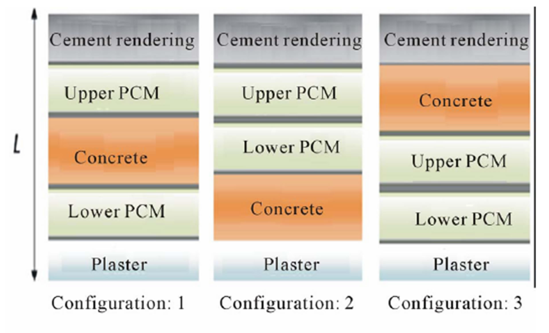
Figure 2. Positions of PCMs integration in referential roof.
lead to development of the following assumptions to define the numerical model:
• In your paper title, if the words “that uses” can accurately replace the word “using”, capitalize the “u”; if not, keep using lower-cased.
• The heat conduction in the composite wall is one dimensional and the end effects are neglected.
• The PCM is homogeneous and isotropic.
• The interfacial resistances are negligible.
• All physical properties of both liquid and solid material are constant.
• The volume expansion is neglected during melting of the PCM.
• The effects of natural convection in the liquid phase of the PCM are negligible. This hypothesis is admitted for thin PCM thickness [5,24]. In this study, the aspect ratio is ~0.01.
2.2. Mathematical Model
Solving the equation of problem for different roof materials and PCM is given by equation (1). Hence the dimensional equation of energy in different parts of system is written as:
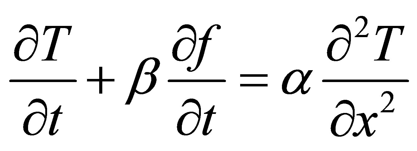 (1)
(1)
 is the thermal diffusivity of i-th material layer,
  the temperature,
  the time, and
  the position which varies inside the layer.
The term  is present only for phase change material PCM during melting at
 , characterized by melting ratio
 , such
  is the latent heat of PCM and
  is the specific heat.
The melting thermal diffusivity of PCM  during melting is calculated using the following equations:
 .
.
Such as the indices , and
, and  indicate respectively solid and liquid phase.
Continuity of temperature and flux are applied in all unions between i-th and (i+1)-th layers according equations (2) and (3) respectively.
 (2)
(2)
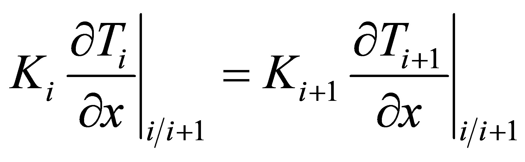 (3)
(3)
where: ,
,  and
and ,
,  are respectively temperatures and thermal conductivities of the i-th and (i+1)-th layers respectively.
  denotes that the calculation is evaluated in the interface between the i-th and (i+1)-th layers.
The boundary conditions on both sides of the roof are respectively:
• Indoor boundary condition :
 (4)
(4)
where  is the thermal conductivity of the indoor layer and
  is the indoor heat transfer coefficient,
  is the indoor air temperature and
  is the temperature on the indoor surface.
• Outdoor boundary condition:
 (5)
(5)
where  is the thermal conductivity of the outdoor layer and
  is the outdoor convection coefficient,
  is the temperature on the outdoor surface,
  is the outdoor air temperature.
  is the solar absorptivity of the outside surface,
  is the solar radiation and
  is the radiation exchange with the sky. These last parameters affecting outdoor boundary condition are calculated for horizontal roofs in Casablanca by using the ASHRAE model [25,26].
The previous system of equation (1) associated to interfaces (Equations (2) and (3)) and boundary conditions (Equations (4) and (5)), has been solved by implicit finite difference scheme. This stable and convergent scheme is able to occur the evolution of temperature profile at each point of the roof.
2.3. Validation of Numerical Solution
The Before presenting the numerical results for the phase change system, the numerical code must be validated by comparison with analytical solution available in the literature.
First, the phase-change model was checked against the classical Newman problem. The PCM is initially at melting temperature  in semi-infinite long rectangular with a uniform cross section. At
 , the surface is kept at a temperature
  and liquefaction of PCM takes place. Position of solid-liquid interface versus time is calculated by numerical code and compared to its analytical values given by the function [17]:
  where
where  is an unknown to be determined by solving the following equation (6) [17]:
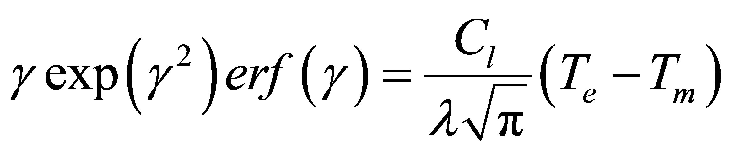 (6)
(6)
Result of comparison between numerical and analytical solutions is reported in Figure 3. It can be seen that the present model agrees well with the results of this study.
The second validation reported in Figure 4 is a comparison of the numerical code with the numerical and experimental results obtained by the study carried out by Amir et al. [3] using the paraffin n-octadecane such as phase change material of melting temperature Tm = 28˚C. The operation of storing electrical energy during about four hours is followed by a release of energy during sixteen hours. The end of the process of storage and the beginning of energy releasing appear in the Figure 4 by a peak representing the maximum value of the PCM temperature. The numerical code is suitable to the same operating conditions carried on a building configuration used in thermal analysis electric heating floor panels with daily heat storage [3]. The results of the comparison between the experimental and numerical temperatures profiles within the PCM show good agreement between the results of this study and the current numerical model. The results depicted in Figure 4 prove that their reliability and accuracy are assured; furthermore this numerical model can give the results to a multilayer roof/wall.
3. Parametric Study and Discussion
Simulation results of the developed numerical code are relating to all months of year. The various configurations shown schematically above (Figure 2) as well as reference roof (Figure 1) have been treated for similar thermal conditions imposed.
The internal temperature is expected to be maintained at a constant temperature  whereas the external temperature follows a sinusoidal temporal evolution which profile is given for extreme period as follows:
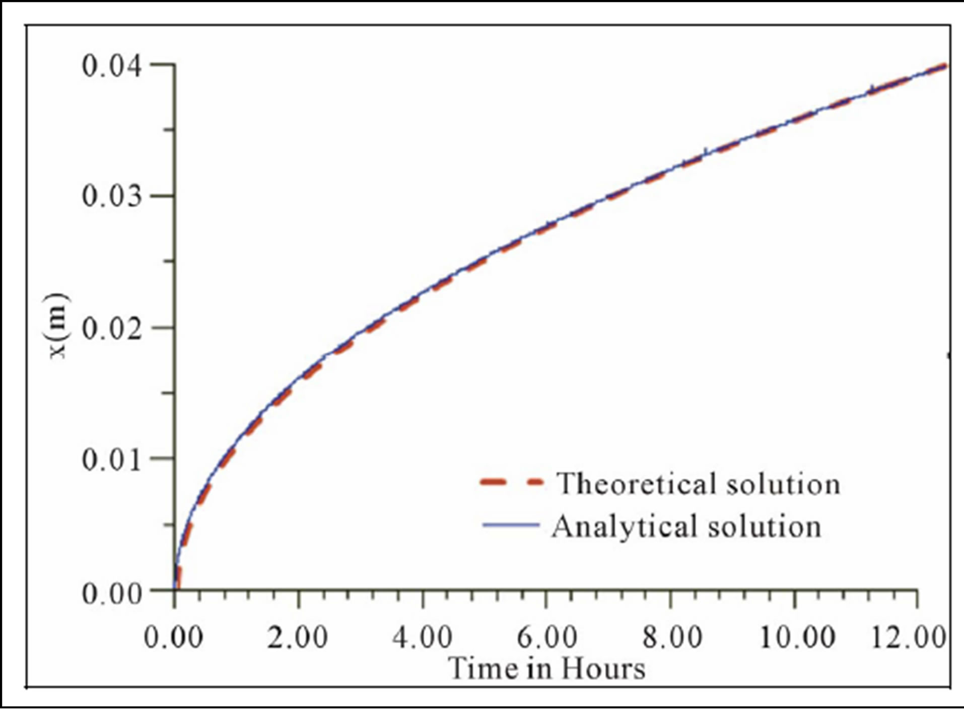
Figure 3. Evolving of melting front position with time.
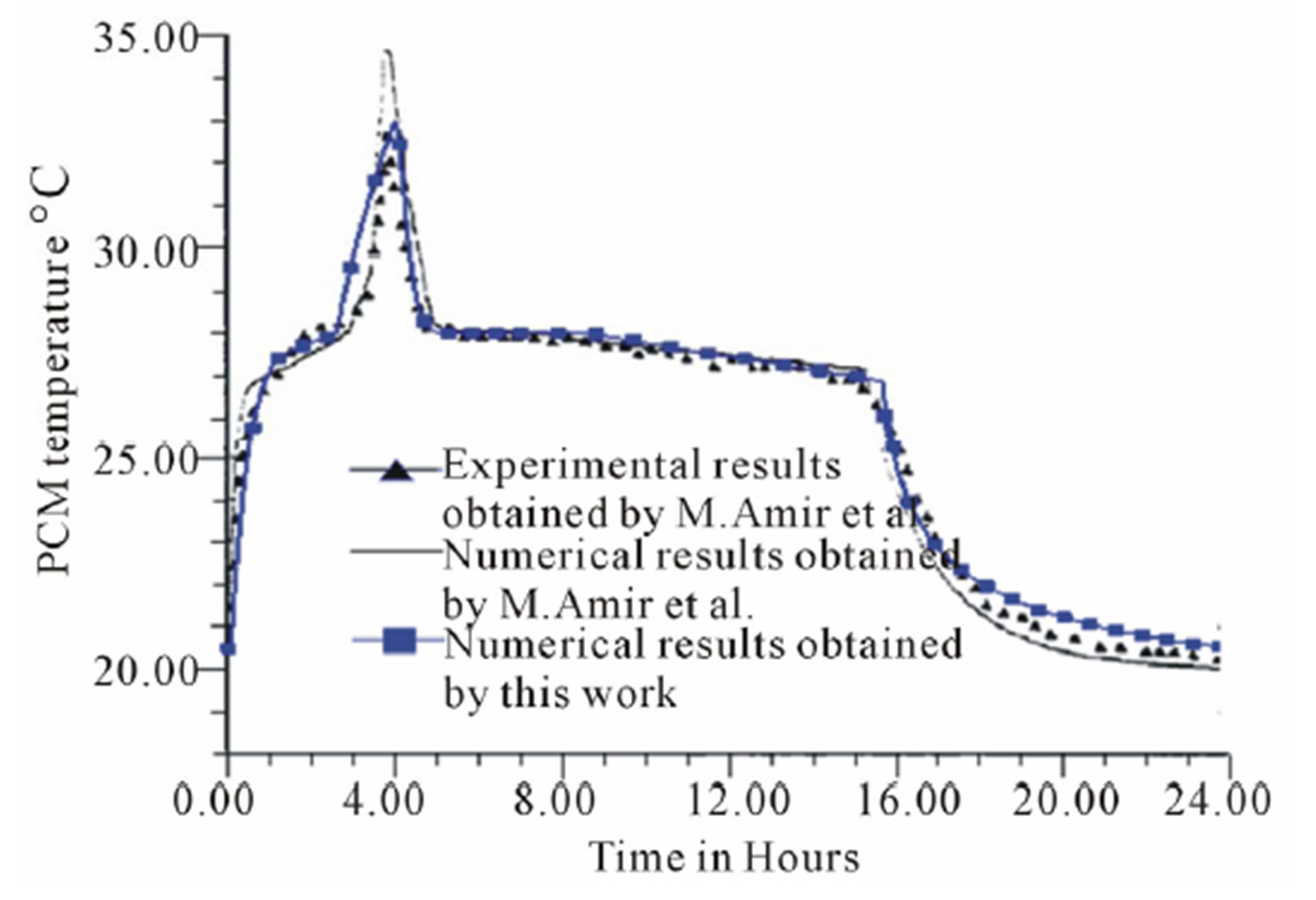
Figure 4. Temperature profile during a cycle of storagerelease.
In summer (hottest period):
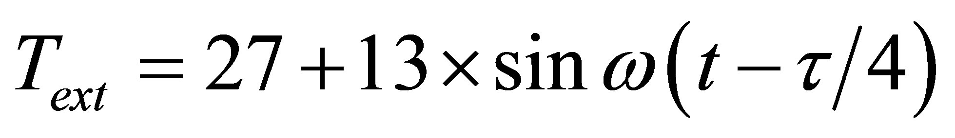 (7)
(7)
In winter (coldest period):
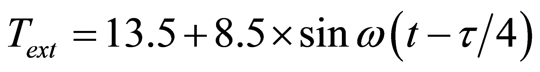 (8)
(8)
With: ,
,  are respectively daily period and pulsation.
In addition to the effect of the variation of the outdoor temperature, the terrace is subjected to the action of solar radiation, approached by the Mediterranean ASHRAE model [25,26].
The effect of these outside conditions at inside roof surface appeared as a heat flow fluctuations. The fluctuations transfer leads to important energy consumption of air conditioner able to ensure an inside constant temperature. This energy consumption is calculated as an average daily at inside roof surface by Equation (9) and also its annual accumulation defined by Equation (10).
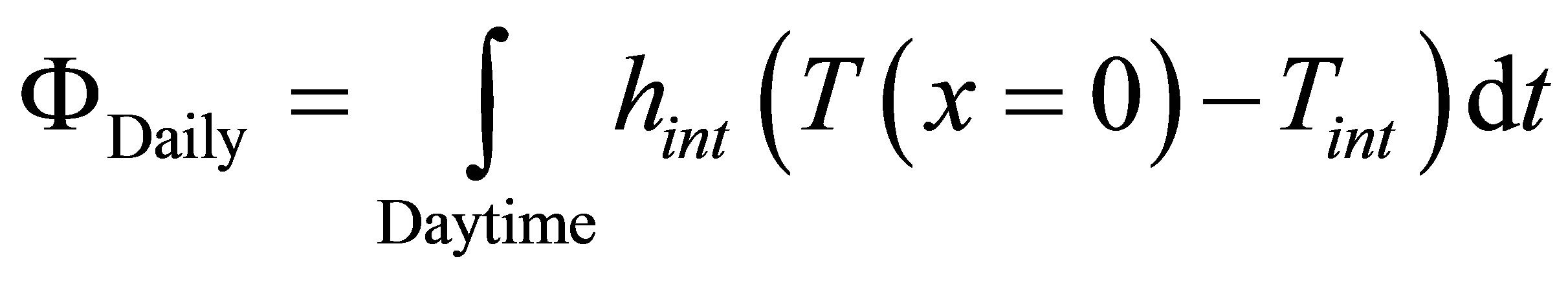 (9)
(9)
x = 0 corresponds to the inner section of the roof
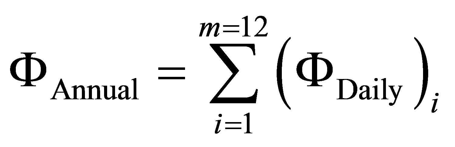 (10)
(10)
Such, that i means the month that varies from January until December.
3.1. Study of Reference Roof
The referential roof is constituted by three different building materials of physical properties summarized in Table 1. This system of roof without PCM undergoes outdoor periodic climate conditions which affects interior comfort. Therefore the annual energy consumption, defined by equation (10), needed to keep the indoor air temperature constant 20˚C, reached 3.686 kWh/m2. Hence it is interesting to check whether the inclusion of PCMs layers at the interfaces of the roof schematized above in Figure 1 can reduce this energy consumption. In order to determine phase changes materials most suitable to reduce the consumption of energy, it requires carrying out a thermal behavior analysis of the referential roof. Temperature evolution studied for two extreme periods; one is hottest, while other is coldest, allows determination of temperature range applicable in all months of year. Levels to take the temperature are chosen according for location designed to insertion of phase change materials that are localized between the concrete and cement rendering, and also between the concrete and plaster. The results summarized in the following Table 2 show that the choice of the most suitable PCM for the warm period is that which at a melting temperature between 24˚C and 34˚C, while the coldest period requires a choice between 17˚C and 23˚C. Hence, it is provided that choice of two PCMs having melting temperature between 17˚C and 34˚C, can achieve most suitable result during all the year. Finally, PCMs added are then a combination of PCMs of melting temperature in range of hottest period with other corresponds coldest period.
Although the literature [9,10] presents a variety of phase change materials, an unavailability of certain physical properties necessary for the numerical study limits the choice of operating PCMs. The phase change materials selected are given in Table 3. There are two kinds of PCMs: one suitable for space cooling and other suitable for space heating. Therefore, it is convenient to modify the design of the referential roof, by inserting two layers of materials as the phase change material (PCM) can store the both hot and cold energy in order to restore it later for minimizing the transmission of outside climate energy in indoor.
Indeed for a conventional roof without PCM, the amount of consumption energy is obviously influenced by the evolving external thermal conditions but also there is physical properties effect of roof components. Cer-
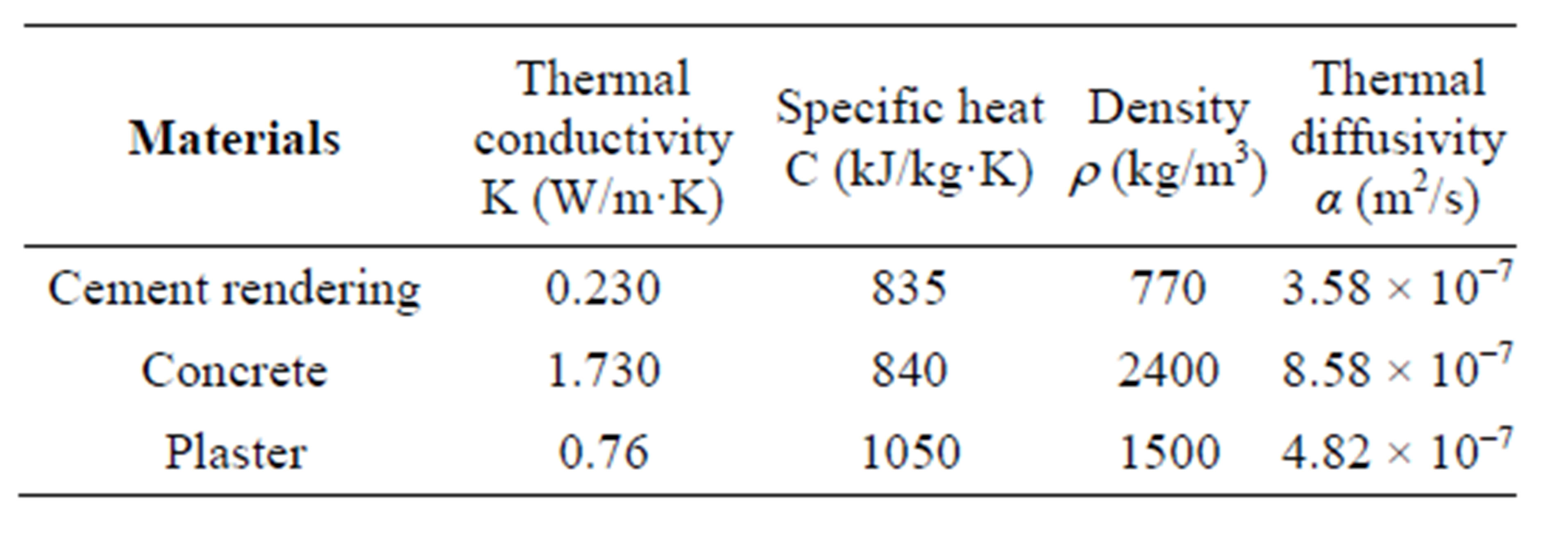
Table 1. Physical properties of different building materials used in the study.
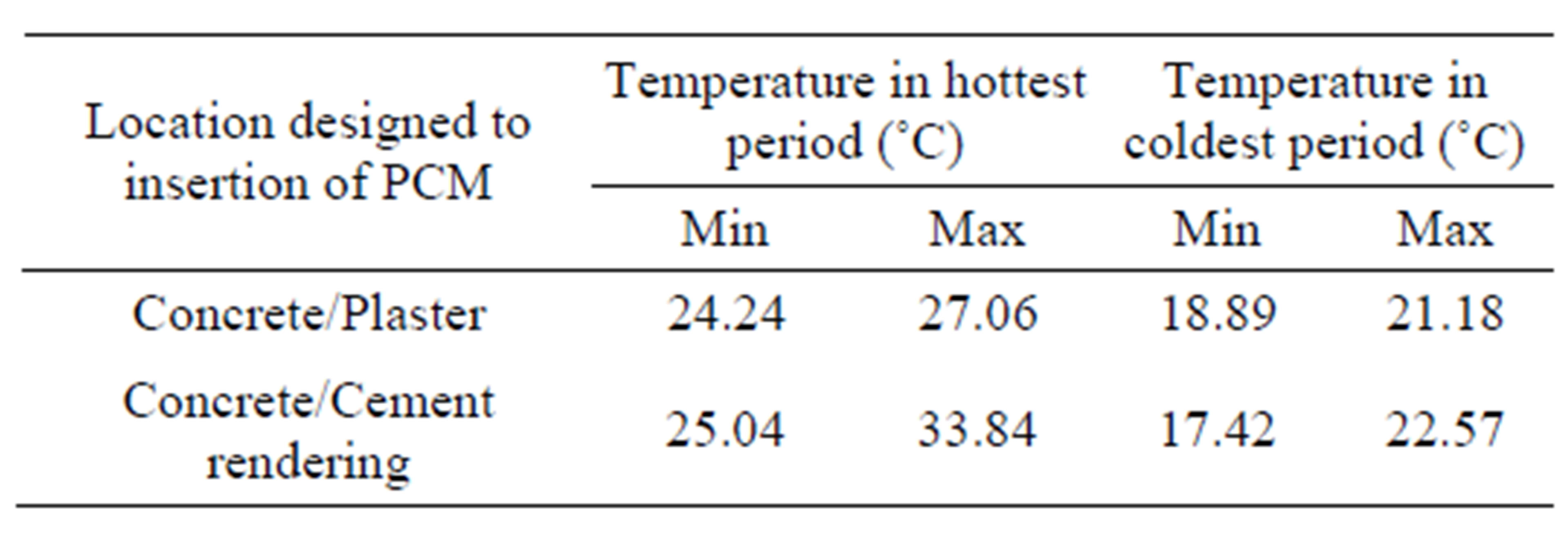
Table 2. Temperature evolution for two extreme periods; one is hottest, while other is coldest.
tainly, the thermal inertia of traditional building compounds used in this study, cheek an important role in delaying the transition of heat flow fluctuations. From Table 1, it is found that the values of thermal diffusivity and thermal conductivity of concrete which possesses thicker part of the roof are higher compared to same physical properties of cement rendering and plaster. Hence lower thermal conductivities and diffusivities of plaster and cement rendering lead to protection around concrete layer against outside climate conditions. This protection can be improved by replacing part of the Cement Rendering and Plaster by a same size of PCMs layers with requirement to keep the same total thickness of the roof. According to Table 3, the thermo physical properties of PCMs provide generally a low thermal conductivity and a less thermal diffusivity which allows to improvement prediction of the thermal behavior roof.
3.2. Comparative Study of the Annual Internal Flux of Different Combinations of Phase Change Materials (PCM)
Numerical study focuses on roof thermal behavior simulation for each combination of selected PCMs. The aim is to determine that which be able to reduce the effect of outside climate energy fluctuations during all year on the air-conditioning energy consumption. The configurations schematized in Figure 2 are carried out in periodic regime laid, under same external environmental conditions. This study includes the various configurations analyzed and processed for all selected PCMs, such as one PCM selected for hottest period is combined with all PCMs selected for coldest period, with swapping of PCMs. The same procedure is repeated for all PCMs of coldest period, where each PCM is combined with others of hottest period. Thus, there are three different configurations with
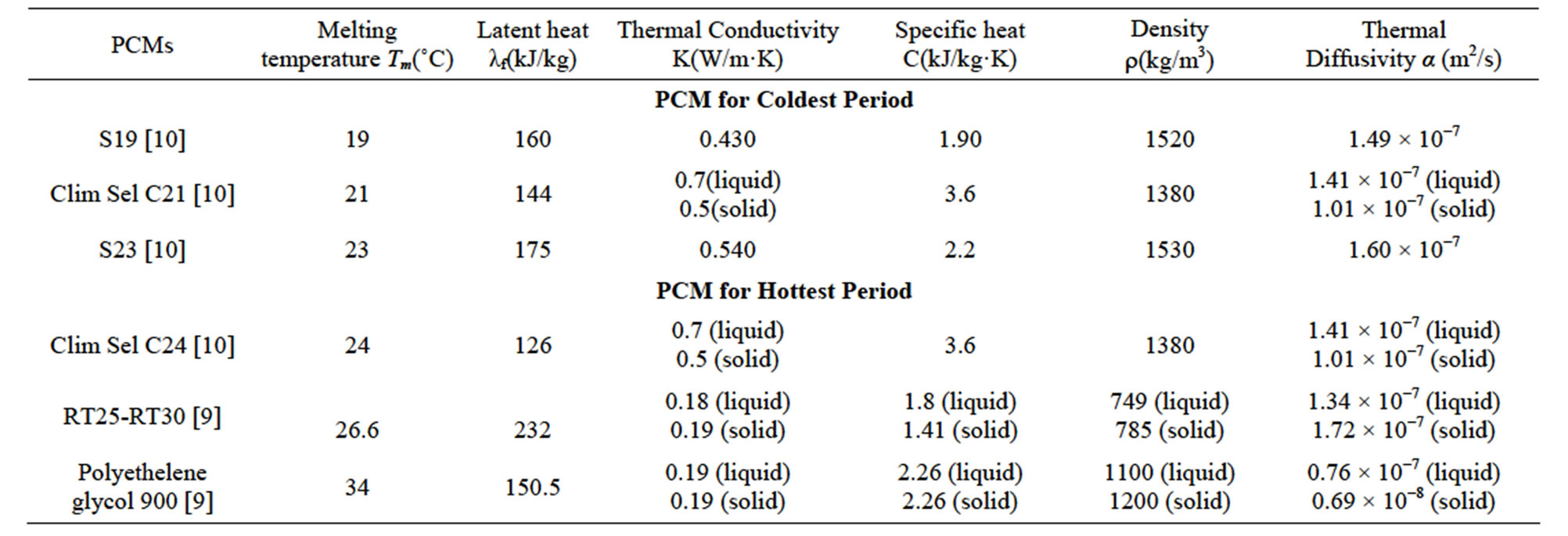
Table 3. Physical properties of selected PCMs.
swapping of PCM selected, such as:
Configuration 1: Both PCMs are separated by concrete layer.
Configuration 2: Both PCMs are above concrete layer.
Configuration 3: Both PCMs are below concrete layer.
Further, these last configurations are compared with referential roof without PCM under the same external conditions and for the same thickness of concrete layer.
The annual energy consumption, defined by equation 10, is calculated for all PCMs combination formed in each configuration and also for roof without PCM. The annual accumulation of the monthly average of daily heat flow is given in (kWh/m2), at the inner face of the roof that is mean in contact with the room at x = 0, where the temperature is kept at 20˚C. Hence its data summarizes  as total of daily energy
  calculated for each months by equation (9), at the inner surface for different cases.
The first observation is that the combination of the same PCM with other PCMs gives different results in terms of energy consumption, to ensure internal temperature fixed at 20˚C. This is also remarkable when going from one configuration to another for the same combination. Generally the annual energy consumption is often shows that the integration of PCMs, improves the residential buildings roof by reducing the energy consumption. This decrease can reach until 0.61 kWh/m2, when PCM of melting temperature 34˚C is up and PCM of melting temperature 21˚C is lower in configuration 2 such as the both PCMs are over concrete, while the referential roof without PCM uses about 3.686 kWh/m2, i.e. reduction of 83%. The importance of studying these combinations in details is summarized in the next section.
3.3. Combination Analysis
In order to assess the study mentioned previously, the results achieved are presented in Figures 5-10. These Figures enable analysis of annual energy consumption
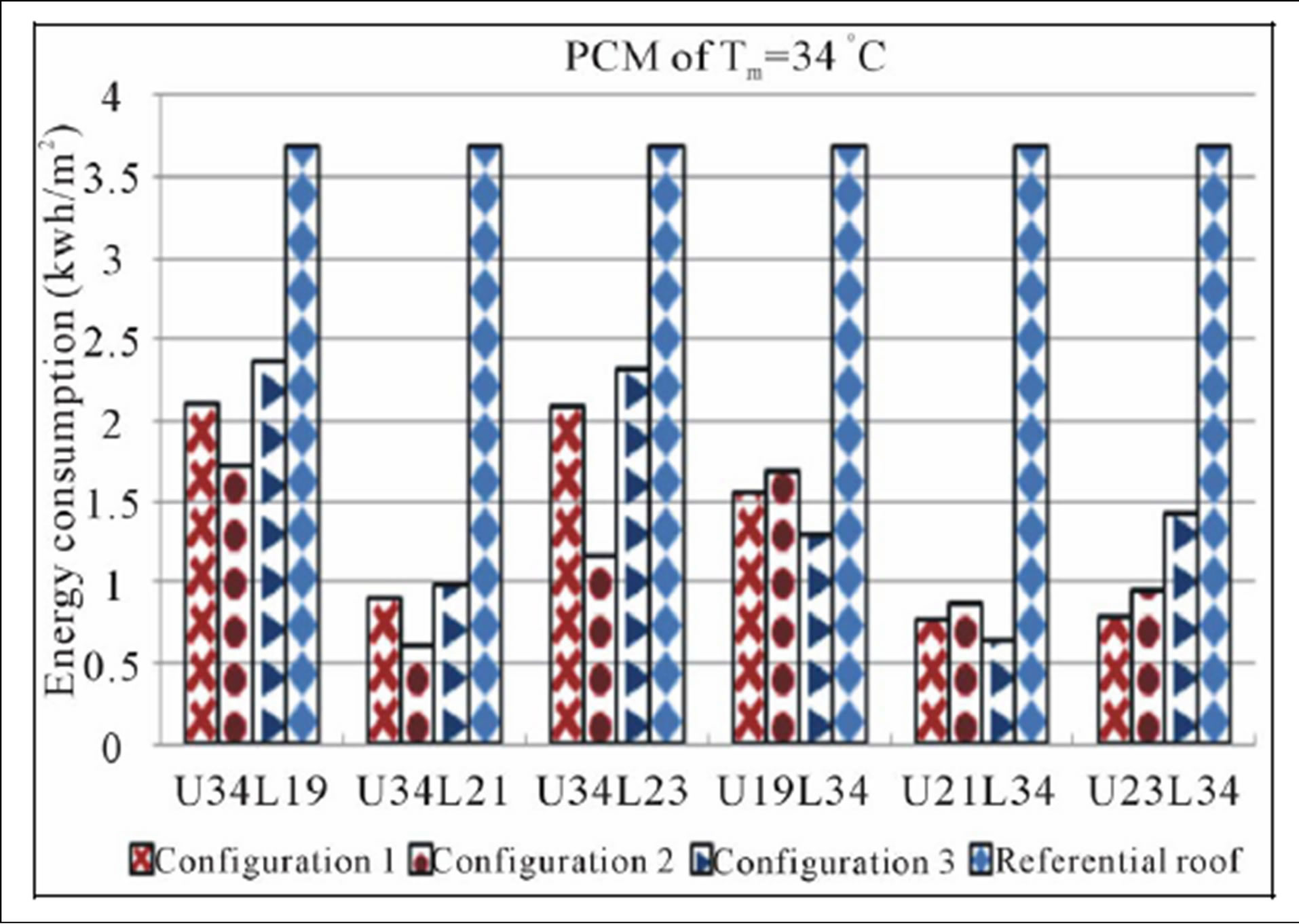
Figure 5. Combinaisons of PCM of Tm = 34˚C with PCMs of coldest period.

Figure 6. Combinaisons of PCM of Tm = 26.6˚C with PCMs of coldest period.
 development for the three configurations and for referential roof.
Generally, the obviously observation as shown in Figures 5-10 is that for roof without PCM, energy amount is greater than roof with two layer of different PCMs. The

Figure 7. Combinaisons of PCM of Tm = 24˚C with PCMs of coldest period.
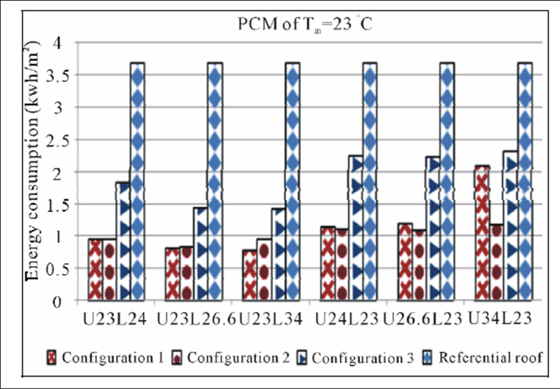
Figure 8. Combinaisons of PCM of Tm = 23˚C with PCMs of hottest period.
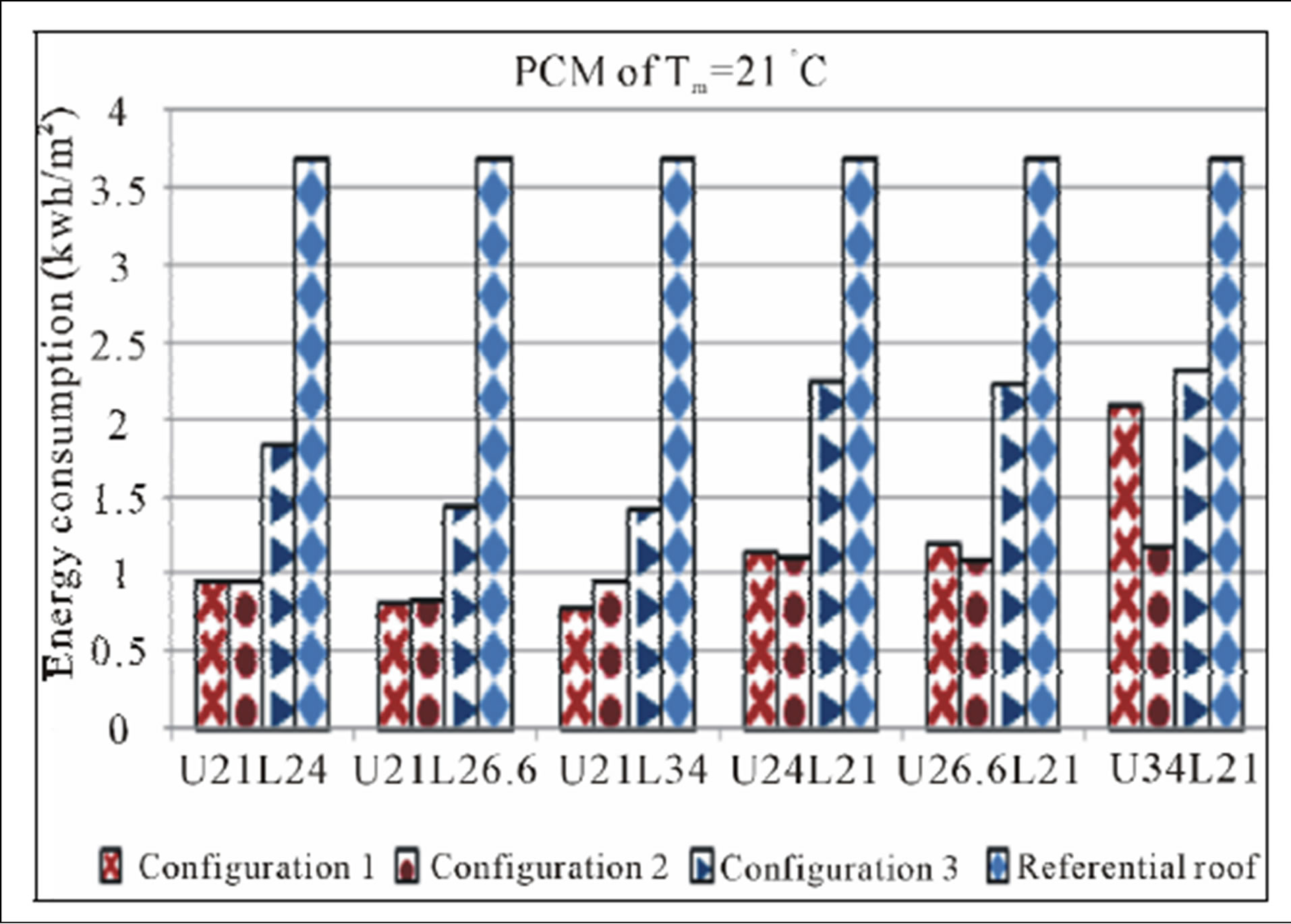
Figure 9. Combinaisons of PCM of Tm = 21˚C with PCMs of hottest period.
integration of PCMs in the roof is always suitable and may even decrease the energy necessary to maintain constant local temperature.
The facts are confirmed for combination of PCMs with
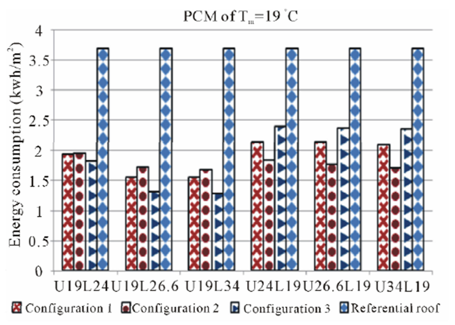
Figure 10. Combinaisons of PCM of Tm = 19˚C with PCMs of hottest period.
significant advantage compared with the roof without PCM regarding the annual energy consumption . Even that is true, but it is not always possible to have a significant reduction as shown results obtained when the PCM of melting temperature 19˚C is combined with the selected PCM for the hottest period. Whereas the insertion of two PCMs with different melting temperature is very important, it is necessary to realize a study corresponding to thermal behavior of roof undergoes incorporation of PCMs. This thermal behavior evolution is influenced by other physical properties besides the melting temperature as latent heat and thermal diffusivity.
Because PCMs are selected according extreme periods, results will be discussed as two sub-paragraphs: one for the hottest period and other for the coldest period. Such a similar notation as U34L19 is used in abscissa axis, means: Upper PCM of melting temperature 34˚C and Lower PCM of melting temperature 19˚C.
3.3.1. Combinations of PCMs Selected for Hottest Period
Figures 5-7 illustrated annual consumption energy according to different combinations of PCMs selected for hottest period with the other PCMs, allow to comparison of three studied configurations.
This shows that location of PCMs having a higher melting temperature (Tm = 34˚C, Tm = 26.6˚C, Tm = 24˚C) , above PCMs with lower melting temperature (Tm = 23˚C, Tm = 21˚C, Tm = 19˚C) is preferred for configuration 2 followed by the configuration 1, while configuration 3 is placed thirdly.
However, when the location of PCMs with lower melting temperature is above PCMs having a high melting temperature, configuration 1 is better than configuration 2, with an even evolution. The results obtained become nearly the same, as well gradually the melting temperature decreases for PCMs hottest period, especially for PCM of Tm = 24˚C. Regarding the configuration 3, which behaves differently, it is obvious that the combination of PCMs selected for hottest period with PCMs of Tm = 19˚C and Tm = 21˚C, leads a saving of energy better than configuration 1 and 2. For PCM of Tm = 23˚C results by these PCMs mentioned previously show that configuration 3 is third in front of configurations 1 and 2.
Generally, for the three configurations, when PCMs selected for hottest period are above of all PCMs of coldest period, the energy consumption is rising compared to the inverse permutation. So the location of PCMs of the upper melting temperature, below to PCMs of lower melting temperature, leads to save the energy designed to provide thermal comfort in room interior.
3.3.2. Combinations of PCMs Selected for Coldest Period
Evolution of the annual energy consumption of air conditioners providing Tint = 20˚C, is evaluated by testing the PCMs selected to reduce this energy in the coldest period. Firstly the Figures 8-10 show that location of PCMs having a higher melting temperature, above PCMs with lower melting temperature is preferred for configuration 2 followed by the configuration 1, whose configuration 3 is placed thirdly. Accordance this order, due to melting temperature decrease of PCMs hottest period. The results of configurations 1 and 2 begin to approach until to have almost a same value, specially for the PCM Tm = 23˚C.
Secondly, the location of PCMs having a higher melting temperature below PCMs with lower melting temperature (Tm = 21˚C and Tm = 19˚C) is preferred for configuration 3 followed by the configuration 1, whose configuration 2 is placed thirdly. Regarding PCM of melting temperature Tm = 23˚C, the classification of configurations is respectively 1, 2 and 3. Accordance this classification, due to melting temperature decrease of PCMs of hottest period, the results of configurations 1 and 2 start approximated until to have almost a same value, exept for the PCM of Tm = 34˚C.
The results mentioned in Figures 8-10 have confirmed for PCMs selected for coldest period the same remark previously concluded, but with one exeption. The location of PCMs having low melting temperature above to PCMs with high melting temperature is relevant, except PCM of melting temperature 21˚C which has evolved inversely, but only for configuration 2. The location below of concerning PCM, relative to other PCMs for the hottest period is slightly important.
3.4. Criteria to Choose the Most Suitable PCMs
To determine the criteria for selecting the most suitable combination of PCMs reducing annual energy consumption through the roof of an air-conditioned room, the results obtained previously should be recapitulated. From the above Figures 5-10, it is obvious that the PCM with melting temperature Tm = 21˚C is most able for reducing energy consumption, whatever configuration of PCMs insertion. This PCM combined with any PCM selected for hottest period, allows save up around three quarters 3/4 of the annual energy consumed by the roof without PCM.
Thus, it appears that the comfort temperature affects the choice of coldest PCMs period whose melting temperature should be close to the desired temperature in the room. This is also true for the PCM with fusion temperature Tm = 19˚C, but its contribution with hottest PCMs period lead to energy supplied greater compared to all other coldest PCMs.
So when the comfort temperature is fixed at specific value, it seems that the most suitable coldest PCM to be combined with the PCMs of the hottest period is the one whose melting temperature is slightly greater, about 1˚C, than the comfort temperature.
The checking of this summary needs to repeat the same study carried out for the comfort temperature at Tint = 20˚C with another comfort temperatures such for example Tint = 18˚C. Knowing that operating intervals for the hot and cold periods of the air-conditioned room at the new comfort temperature Tint = 18˚C lead to the same selection of PCMs listed above in Table 3, the results of this further study summarized in Figure 11 shows a minimum energy consumption for all combinations made by the PCM of Tm = 19˚C whatever the integration configuration in the roof.
Regarding the selected of hottest period PCM, the choice should be based on the offset of excess heat caused by the increase in temperature up to a maximum value. In this effect PCM of temperature Tm = 34˚C is most likely to be convenient for both comfort temperatures Tint = 18˚C and 20˚C. For other comfort temperatures tested, the results obtained confirm the same criteria previously mentioned.
Hence according to this remark, must be selected the most appropriate configuration for combinations containing suitable PCMs. Moreover the most favorable combinations of phase change materials for each configuration will be selected according to the top yields achieved regardless combinations of PCMs, such as the results will be discussed in the next section.
3.5. The Most Suitable of Phase Change Materials Combinations for Each Configuration
As already mentioned the top yields achieved by each configuration will be discussed for both comfort temperatures Tint = 20˚C and 18˚C. For this purpose, a comparative study of the relative deviation of energy con-
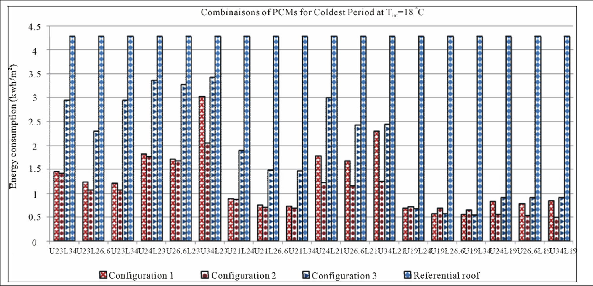
Figure 11. Combinaisons of PCMs for coldest period at Tint = 18˚C.
sumed is conducted for each combination relative to the referential roof calculated as:
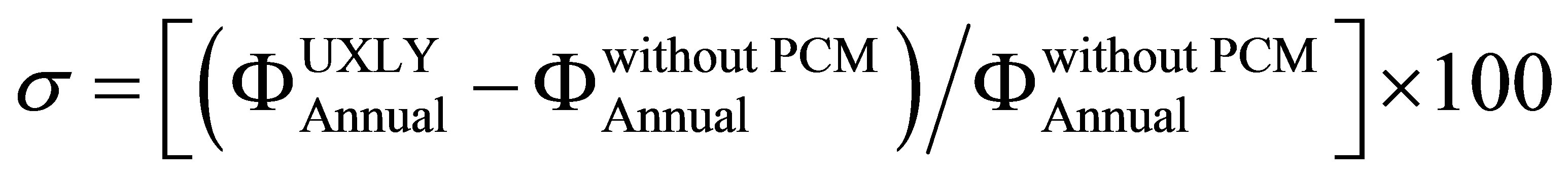 (11)
(11)
where:
• UXLY is such X and Y are two different melting temperatures PCMs, while U and L means that PCMs X and Y are respectively Upper and Lower.
•  is the annual energy consumption at the inner surface of roof without PCM.
•  is the annual energy consumption at the inner surface of roof with PCMs of any combination of PCM X and Y.
Numerical values of this parameter, defined by equation (11), are reported respectively below in Tables 4 and 5 for comfort temperatures Tint = 20˚C and 18˚C, according to top yields for the three configurations of PCMs.
According to Tables 4 and 5, performances can reach respectively over than (79% and 86%) in the energy economy compared to roof without PCM for three configurations 1, 2 and 3, respectively for comfort temperatures Tint=20˚C and 18˚C. For the three configurations (1, 2 and 3), the best performance is associated to the presence of PCMs of Tm = 21˚C and Tm = 34˚C for comfort temperatures Tint = 20˚C, while for comfort temperatures Tint = 18˚C the best performance is associated to the presence of PCMs of Tm = 19˚C and Tm = 34˚C.
Since in configuration 1 the both PCMs are separated by concrete, always a part of energy is absorbed by concrete layer. Then, it appears that the latent heat storage in configuration 2 and configuration 3 is more important
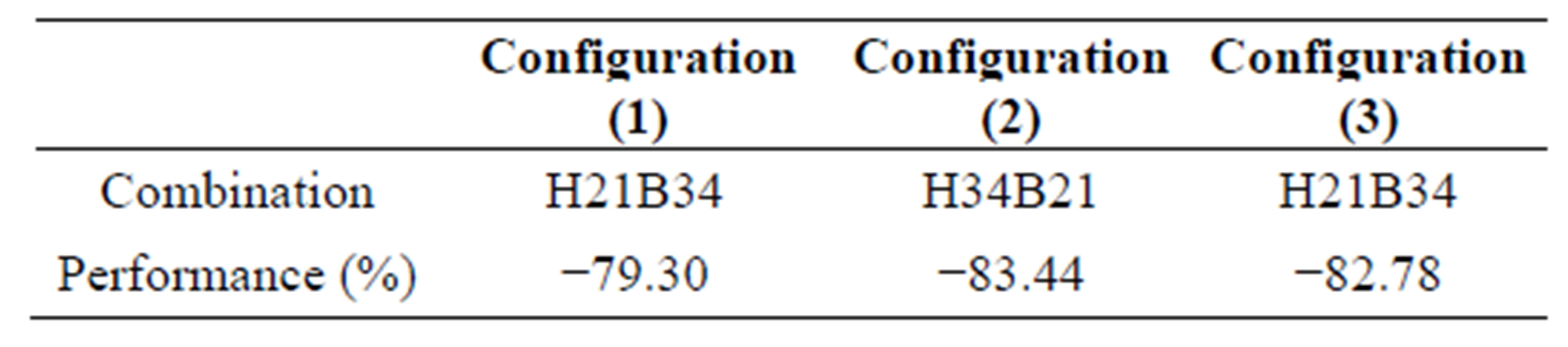
Table 4. Top yields for three configurations for comfort temperatures Tint = 20˚C.
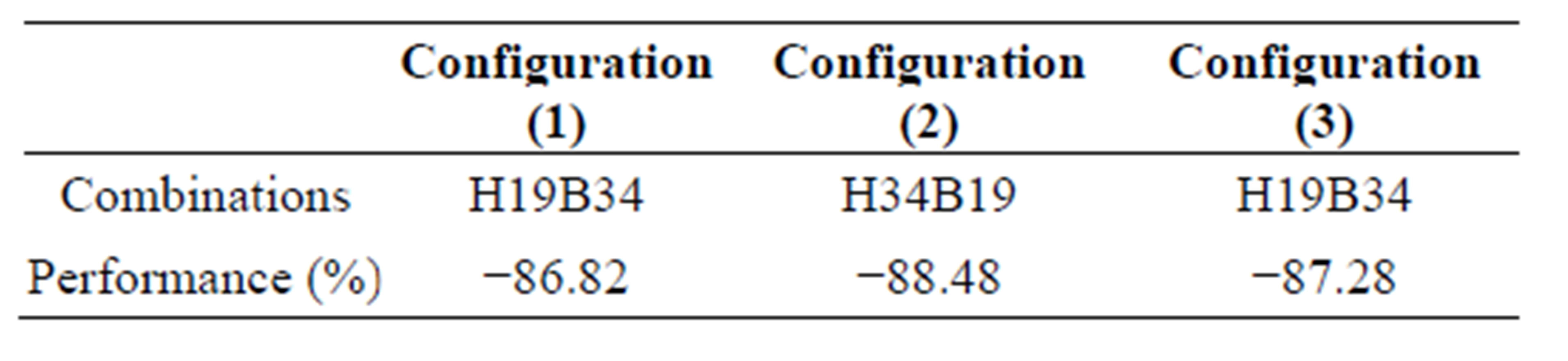
Table 5. Top yields for three configurations for comfort temperatures Tint = 18˚C.
compared to configuration 1; therefore its performance is lower compared with other configurations. While for configurations 2 and 3, these yields can reach maximum values shown in Tables 4 and 5. In configuration 2, the both PCMs are above of concrete; this means that the highest level of heat transfer is received by PCMs. Therefore, when the melting temperature of the upper PCM is higher than the lower PCM, the performance of the energy consumed is important However, third configuration where both PCM are below of concrete, this means that the highest level of heat transfer is received by concrete layer. Thus melting temperature of the upper PCM is lower than the below PCM and provide the important performance of the energy consumed.
4. Conclusions
Thermal behavior of two roofing systems is studied, under climate conditions of Casablanca city during all year. One roof is constituted just by conventional building materials. In the other hand, two phase change materials (PCM) are introduced in different locations within traditional roof.
The parametric study produces the roof thermal behavior was carried out using a numerical program developed and successfully validated. Three multilayer roofing configurations provided with two phase change materials have been treated at different comfort temperatures; such results of two comfort temperatures 18˚C and 20˚C are detailed.
In general, combining two PCMs leads to lower annual energy consumption, when the PCM for coldest period is placed above, that is to say, close to the external environment. This is due to the fact that when it is moved down, it contributes less by a phase change as it does not undergo to external excitation.
Even the integration of PCMs in the roof is suitable, it is not always possible to have a significant reduction. Hence it is necessary to realize a study of thermal behavior under internal and external conditions imposed.
In addition, the criteria for choosing the most suitable PCMs, according to the results obtained show that each PCM must correspond to one temperature interval (hottest or coldest) with a choice of a PCM able to compensate the maximum consumption of energy imposed by the highest temperature of the hottest period, however, the other PCM suitable for the cold period should be that its melting temperature is slightly above that of comfort around +1˚C. Eventually it seems that the thermal comfort level dictates the choice of PCM for cold period while the PCM selected for hot period should be able to compensate the highest temperature transferred to roof studied.
Finally, the three configurations lead to different results, depending on the combination of PCMs. This difference becomes less important when the criteria to select the PCMs are respected.
NOTES