Applying Conventional Combustion Science and Technology to Alternative Energy Resources in Industrial Systems ()
1. Introduction
Fires and flames have played a very intimate role in man’s life since ages unknown. Our civilization breeds on the combustion of fuel for useful heat in the industries, at home, in the streets, and actually in every aspect of human life [1]. With the exception of a small monopropellant and tripropellant reactant system used in rocketry, combustion is generally understood to entail the chemical reaction between materials-fuel and oxidant [1,2]. The combustion of coal, oil or gas for the purpose of heating and power production is an example of stationary equipment. When burning isolated briquettes, a porous bed of coal on a stoker, a fine jet of pulverized coal, a liquid spray and a gaseous fuel jet are a few typical combustion problems associated with these equipments.
Life hinges on energy and a good and sustainable source is the penultimate desire of all nations. In all African countries wood fuels have been and will continue to play a significant role in meeting the energy demand for cooking, water and space heating [1-4]. The increasing trend of wood fuel utilization shall be sustained for a long time as urbanization in most African countries implies a shift from fuel wood to charcoal; and the low carbonization efficiencies of charcoal production processes mean greater wood demand and consequently greater pressure on forest resources [4]. The level of dependence on wood fuels by African countries ranges between 61% and 86% of the primary energy need and from 74% to 97% of the domestic energy needs [3,4]. Wood fuel consumption remains a principal contributor to the rate of wood removal in Africa. It is estimated that over 92% of the total wood harvested in Africa goes for energy purposes [4]. It is, therefore, time to consider wood fuel use as a local and global environmental issue in Africa, while also considering its contribution to the global greenhouse effect.
For the solar energy source, though it is available to the majority of the nations of the world, the technology for its conversion is yet to be firmly established; for the nuclear energy source, whereas attractive, political, economic and environmental considerations have hampered and continue to hamper its full exploration and application. The products of crude oil have become socially, culturally and traditionally acceptable. It has become the energy resource of the world. With the source now showing signs of depletion, the facts clearly indicate that there has to be a major change in the pattern of usage of the energy in order to maintain a healthy world economic society in the very near future. The extensive research works that have been done in this area have drastically reduced the processing and utilization cost of the resource. This is particularly responsible for the institutionalization of oil and gas [5-11]. Now, faced with the impending decline in the oil reserves, attempts have been and are being made to: exercise greater caution and economy over existing uses of the energy resource; stop the flaring of associated gases; improve combustion facilities towards greater fuel economy; design systems to economically use the generated energy; match largescale availability to large scale consumption or demand and apply special quality fuels to special requirement areas. Yet beyond all these, the time approaches when even the world supply will become inadequate. Research must, therefore, be directed at areas that are expected to open a new alternative, renewable energy sources that will help to avert the problems that could arise during the critical transition between the capital (depletable energy resources) and the income (renewable energy resources) systems, particularly now that the demise of the former is expected to precede the full development of the later.
The productivity and uses of wood as an energy resource and for other activities have attracted considerable attention, which resulted in the development of some wood through hybridization and investment in forestry but very little or no attention has been given to grasses and grasslands [5-7]. This is despite their importance in the global carbon budget and the fact that they have the same botanical features with wood [5]. It has been estimated that while tropical forests that are now becoming denuded of trees, store about 19% of the total carbon sequestered by terrestrial communities each year, tropical grasslands are credited with over 26% [8,9]. The full account of the turnover of grasses in estimating productivity, below ground biomass and yearly variations in relation to climatic fluctuations is scantily available. However, the area occupied by tropical grassland varies between 15.0 and 24.6 million square kilometers of the earth’s surface [8-10]. In addition, periodically inundated grasslands result from deforestation and constant annual bush fire [5,7,11-16]. Moreover, grasses and weeds grow everywhere, around houses, under trees, etc. Often grasses, weeds and leaves of trees around homes are cleared, gathered and burnt. The very high rate of regeneration of these grasses, weeds and leaves shows that it will be more environmentally friendly to use as fuel for the carbon dioxide that will be released when they are burnt will be required for their regeneration [17-26]. The application of these resources as energy materials will reduce the pressure on the forest and consequently reduce deforestation, soil erosion and desertification. Furthermore, studies have shown that these materials are adequately available as energy resources [27]. The histology or the structure of the tissues making the organs of different plants and the anatomy of the respective plants internal structure vary only with the morphological characteristics. The variation from plant to plant is negligible, and therefore can be ignored as far as this study is concerned. The leave is the flattened, lateral and out growth of the stem or branch, developing exogenously from anode and having a bud in its axil [27-36]. The leaf is, therefore, a partial stem or a branch having limited growth. They can therefore be treated as wood.
In this study, attention is focused on designing a burner to combust these materials: lower monocots—grasses and sedges, the annual, biennial and perennial dicots, and the leaves of some higher deciduous dicots (sometimes referred to as lower grade biomass) in an industrial setting.
The rate of burning of any fuel is strongly influenced by the heat flux incident upon the fuel surface. In the case of solids, reaction takes place at the surface, while in the case of liquids and pyrolysing solid, it takes place in the gas phase. The combustion of a carbon particle is accompanied by high surface temperatures at which it becomes incandescent (e.g. glowing charcoal) and much of the heat is lost to the surroundings by radiation. In order to reduce the radiation lost to the surrounding, the fuel is usually finely pulverized. Whereas the burning rate of liquid fuel and pyrolysing solid fuels strongly depends on the rate of heat transfer to the fuel surface, that of simple solids depends upon the rate at which the oxygen diffuses to the fuel surface. Once all the volatiles have been expelled, the carbonaceous residue of pyrolysing solid behaves in the same manner as a simple solid [37-42].
Generally, it can be seen that fuels burn only in the gaseous or vapour phase in contact with a gaseous oxidant. Gaseous fuels, therefore, only require mixing prior to ignition and combustion, whereas liquid fuels also require vaporization while solid fuels need energy from external source or from the flame itself in order to pyrolyse and provide combustible gases. Industrial burners are often comparatively large in size, energy demand, air, fuel demand and hence the rate of combustion. A different manner of fuel feed is, therefore, often used. This type of fuel shall, therefore, needs to be used in its pulverized form.
Pulverized fuel firing is a method whereby the finely crushed fuel is carried by air to the burners. When discharged into the combustion chamber, the mixture of fuel and air burns in a manner very similar to that of the combustion of gaseous fuel [39]. The economic motives for the introduction and development of pulverized fuel firing in power stations and large industrial furnaces are already well known. For this type of fuel, however, cleaning prior to pulverizing may be necessary.
2. Methodology
The burner is designed to be mounted horizontally in afurnace. The burner will utilize the energy in the incoming air stream to move the powdered fuel into the inlet of the venturi. The fuel falls under gravity from ports in the fuel nozzle or spud and they are picked up by the primary air into the venturi throat where they mix thoroughly. The air/ fuel mixture then flows through the diffuser and its extended downstream section before entering the premixed burner tip section. Minimizing the momentum losses associated with the venturi system was considered along side trying to optimize the burner design to maximize entrainment performance. The inlet was designed as a well-rounded bell entrance [40]. This will help minimize the momentum losses through the venturi system. In burner manufacturing, the bell inlet is designed with a radius, r, with a value that is at least 20% of the hydraulic diameter, Dh, of the throat i.e.,
 (1)
(1)
For premixed burners that consume large pressure drop through the exit, a smaller venturi throat diameter is required for optimum performance. The throat length is another important parameter in burner design. It is generally recommended that the length of the throat should be approximately 7 times the throat diameter [40]. To reduce momentum losses, it is also recommended that the total divergence angle of the diffuser section be less than 100 [40]. The down stream section of the burner is usually a straight pipe that connects the exit of the diffuser section with the burner tip. The length of this section is often determined by the thickness of the furnace wall and the mountings requirements.
Most of the parameter necessary for the determination of the size of the throat of the venturi and hence the sizing of the burner depends on the amount of air required for the combustion. And the amount of air required can be obtained by setting up the combustion equation, hence invoking the general combustion equation;
 (2)
(2)
Recalling that the ultimate analysis of Biomass gives elemental carbon, Hydrogen, oxygen and Nitrogen, the combustion equation will reduce to
 (3)
(3)
Also,

On neglecting the nitrogen and sulfur then,
 (4)
(4)
The main constituent of wood, leaves and grasses is cellulose (C6H1005). Firstly, a stoichiometric combustion equation has to be set up, in order to determine the quantity of combustion air that will be necessary for complete combustion. Hence,
 (5)
(5)
n1 can be determined by investigating the carbon balance, from where n1 = 6.
Similarly, n2 can be determined by examining the hydrogen balance from where n2 = 5.
The oxygen balance can then be computed as

Also the Nitrogen balance can be treated as

That is 22.56 moles of Nitrogen will accompany 6 moles of Oxygen to combust one mole of the fuel.
Hence, the Air/Fuel ratio on molar basis is

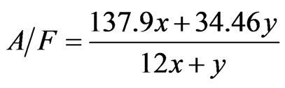
The air/fuel ratio for stoichiometric combustion on the basis of mass can be computed out of the (A/F)s by introducing the mass of the materials: i.e.
 (6)
(6)
where 28.96 is the molar weight of air. The molar mass of the fuel material can be calculated from its chemical equation while remembering that oxygen is not a part of it. Hence, the molar mass of the fuel is

Thus

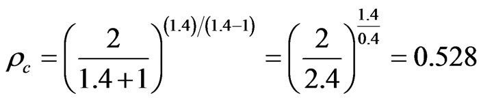
In burner engineering equations based on ideal gas laws and the assumptions of ideal flow are used to calculate the flow rate of fuel [41,42]. The first step in calculating the amount of fuel flow is to determine if it is operating below or above the critical pressure. This can be determined by calculating the critical pressure ratio defined as
 (7)
(7)
where

and Pb = atmospheric pressure in absolute terms; Pf = fuel pressure in absolute terms.
If Pc > Pb/Pt, then the fuel exit the orifice at sonic conditions If Pc < Pb/Pt, then the fuel exit the orifice at subsonic conditions.
The second step is to determine the mass flow rate, m,
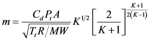 (8)
(8)
For sonic conditions, and for subsonic conditions
 (9)
(9)
where
 (10)
(10)
 (11)
(11)
 (12)
(12)
 (13)
(13)
witrh Cd = orifice discharge coefficient.
Particulated gas like carbon monoxide has specific heat ratio, k. of 1.4. [42] hence,
The powdered fuel contained in the magazine is at atmospheric pressure hence,

Thus, the fuel is to exit the orifice at subsonic conditions since Pc < Pb/Pt.
Therefore,

Te is ambient = 30˚C = 303 K; Pb = 101.33 KN/M2;

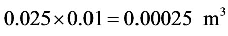
It, therefore, follows that 0.491 kg of pulverized biomass will occupy a volume of 1 m3. And this will require about 5 kg of stoichiometric air for its combustion.
Using 20 pores of diameter 0.02 m each to release the pulverized fuel into the air stream, will give a total release area of

If the content of a column of the above area is 10mm high, the volume of the biomass powder that will be let out at the instant is
But the density of the fuel, r, is r = 0.491 kg/M3.
Hence, the mass of biomass that will be released at an instant is

The air that will be required to accompany this fuel can be computed from the (a/f)s earlier calculated. That is the required air is = 0.00012275 × 12.086 = 0.001483556 kg of air.
The flame speed for Biomass material is approximately 0.244 m/s [38]. This is the final velocity, i.e., the velocity at the tip of the burner and since the mass of the fuel is only 8.33% of the mass of air, the mass of the fuel can be ignored in determining the dimensions of the burner.
Hence, the mass flowrate will be

But m = ρAV.
Hence
The diameter, db, of the burner can therefore be evaluated as

This is the diameter of the final divergent part of the nozzle. The density of the mixture is expected to remain constant as pressure change is negligible [40]. So, putting the throat diameter at 0.06 m (at 20% excess air) will give a throat velocity of 4.073 m/s and a convergent velocity of 0.0675 m/s.
A 9˚ convergent/divergent angle is usually recommended for burners nozzles [40]. From the schematic diagram of the nozzle shown in figure 1, the nozzle can

Figure 1. A schematic diagram of the nozzle.
be sized as follows:

Also the length of the throat is often taken as about 7 times its diameter [40], hence the length of the throat will be.

The final sizing of the burner is the determination of the wall thickness and treating it as a pressure vessel, a thickness of 0.00577 m was arrived at. The schematic diagram of the burner is as shown in figure 2.
3. Tests and Results
Test Procedure
The burner was tested in a 0.7 m × 0.6 m × 0.6 m furnace, having been built as shown in figure 2. The burner was inserted at the left wall inclined at 30˚ to the horizontal. A centrifugal fan was used to supply the needed combustion air. The thermocouples were inserted 88 mm into their positions in the walls of the furnace. The new fuel, well pulverized and dried, a cooking gas bottle and the air blower were connected to the burner via hoses. The digital thermometer and blower were then connected to power source. Three experiments were executed: burn the cooking gas alone, burn the new fuel alone and burn the new fuel mixed with cooking gas.
4. Results and Discussion
Temperature readings were recorded at five minutes intervals as depicted in the table 1.
The results as depicted in table 1 and figure 3 show
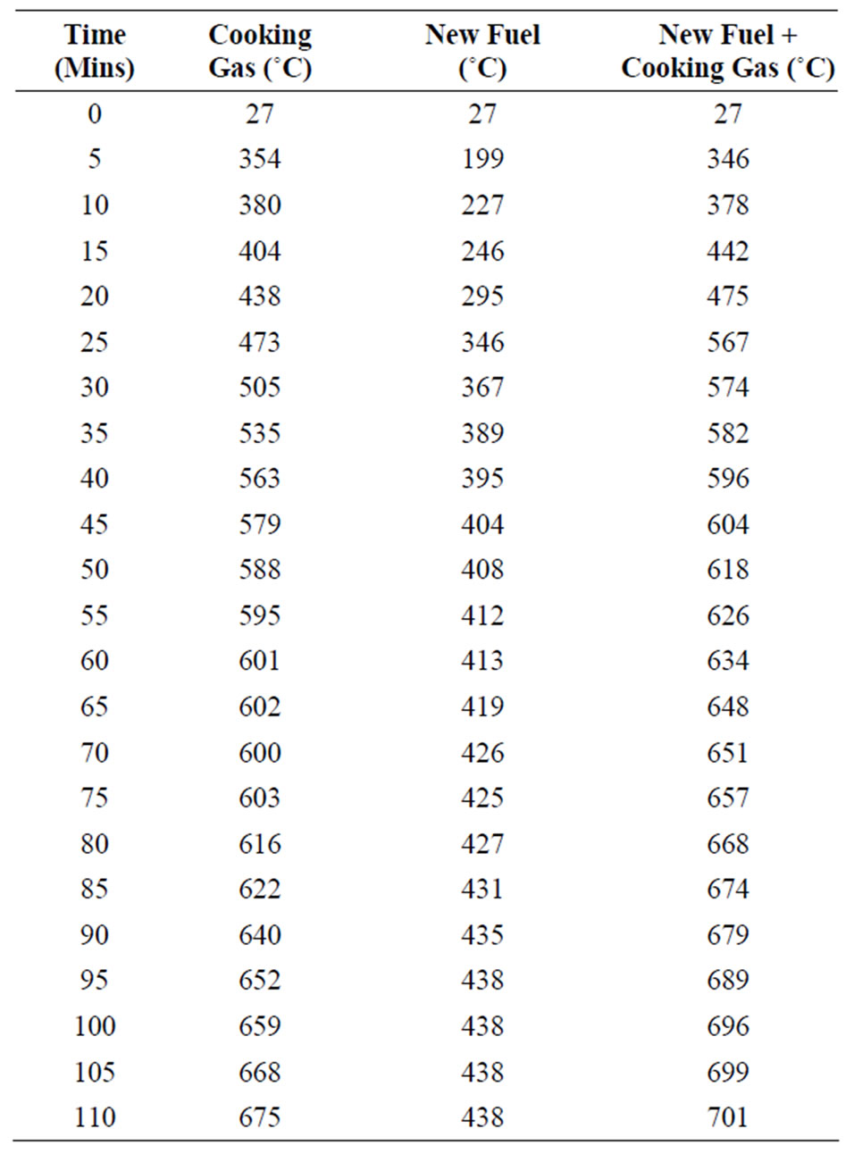
Table 1. Temperature and time record.

Figure 3. Burner’s behavior with different fuels.
that for gas as fuel the temperature profile started very steeply at the beginning. The temperature rose to 675˚C in 110 minutes. It can be seen from the table and graph that the temperature profile of the mixture of the pulverized lower grade biomass and cooking gas overtook that of pure cooking gas in the 15th minute. The temperature hit 701˚C in 110 minutes as the irradiative effect of the biomass particles enhances the heat transfer rate. It can be noted also that the temperature profile is smoother with the mixture than with the cooking gas. This will have a positive effect on any heating process and on heat stress on materials. Similarly, it may be noted that the temperature profile for pulverized lower grade biomass fuel rose slowly and tend to stabilize at 438˚C, this is as a result of the fact that the pulverized lower grade biomass has much lower calorific value than the cooking gas. The experiment also shows that it will cost $8 using gas to melt a given quantity of aluminum dust, while it will cost $4.66 using the mixture of the new fuel and cooking gas and using the briquetted renewable energy resource in the designed burner it cost only $0.005 to melt the same quantity of aluminum.
5. Conclusion
It has been proved through this work that it is possible to combust this new fuel material—lower grade biomass by using conventional facilities in an industrial setting. It was also discovered that the cost of a heating process can be drastically reduced as it cost $8 using the cooking gas and $4.66 using the mixture of the new fuel and cooking gas. Thus using this new fuel or a mixture of it and the conventional fuel will not only reduce cost but will also prolong the life of the existing known conventional resources.
NOTES