Crossed Intralaminar Screws for Fusion of the Cervicothoracic Junction and the Thoracic Spine: The Experience in an Iberic Service with Case Series and Review of the Current Literature with Technique Description ()
1. Introduction
In 2004, Wright described the C2 translaminar screw fixation, which involves the insertion of bilateral screws into the lamina of C2 in a crossing fashion that is then connected to C1 lateral mass screws.
Wright states that anatomic variability of the foramen transversarium in the body of the axis can preclude safe transarticular C1 - C2 screw placement in up to 20% of patients and C2 screw fixation with pedicle screws remains a significant risk to the vertebral artery. So, he describes a novel technique of C2 rigid screw fixation using bilateral, crossing C2 laminar screws, which do not risk to lesion the vertebral artery during C2 fixation [1] .
Other popular indication of use of laminar screws was on the C7 vertebra because the insertion of transpedicular screw fixation at this level has a difficult feasibility due to shoulder shadowing seen in tradional fluoroscopy. Also, lateral mass screws at this level have a disadvantage to exhibit low resistance to pull out. We present the use of laminar screws as a safe option, especially in long constructions involving cervico-thoracic junction.
The advantages of using laminar screws in C7, are:
ú No risk of damage to the vertebral artery when it courses into transverse foramen;
ú No need to use fluoroscopy or navigation systems;
ú Direct visual placement of screws, using posterior laminar cortex as guide;
ú Tactile feedback;
ú Alternative method when anomalous anatomy of pedicles is present;
ú Not very time-consuming procedure;
ú Does not require extensive spine surgical skills.
McGuirt et al., in 2009, compared the transpedicular fixation in Th1 and Th2 versus intralaminar fixation in long subaxial cervical constructs on human cadaveric spines and found a minimal difference after cyclical loadings between translaminar and transpedicular screws. His studies concluded that upper thoracic translaminar screws are a biomechanically effective option to stabilize rigidly the cervicothoracic junction [2] .
In 2010, Kretzer et al., conducted a study, in cadaveric models, about biomechanical resistance comparing the laminar and transpedicular screws fixation involving Th1 and Th2 vertebrae. They found that translaminar screws in the upper thoracic spine offer similar stability to pedicle screw fixation for constructs bridging the cervicothoracic junction. Small difference in range of motion must be clinically weighed against the potential benefits of translaminar screws insertion at Th1 - Th2 [3] .
2. Surgical Technique
As described by medical literature, the most important is to identify the entry point. This point is always located at the spinolaminar junction, pointing to the junction between the lamina and the lateral mass [4] [5] .
The authors advice that both: entry point and screw length must be calculated based on CT scan slices. Attention must be taken when perform this technique for 3 points:
1) the screw diameter;
2) the angulation during the insertion;
3) level of screws insertion in the lamina.
The diameter of laminar screws must be measured in the CT scan before the procedure. If the screw is too long, it may injure the facet joint or even the cervical nerve root. Also, angulation during the insertion must be calculated in order to prevent its penetration in the ventral surface of the lamina and injury to the spinal cord. The direction is also important to avoid the collision of two screws against each other (in the case of bilateral screw insertion).
We strongly advise the accurate identification of the entry start point for the screws in order to reduce breaches of the dorsal lamina cortex.
For bilateral crossing intralaminar screws, the direction and the level of insertion must be taken in mind in order to prevent screw collision at the midline. This collision occurs when both screws have the same level entry point and as a result, they collide and the trajectory of the second screw can suffer a detour. To avoid this, the first screw’s entry point should be close to the rostral margin of the spinolaminar junction and the other screw entry point is made is at the level of caudal margin of the spinolaminar junction. Identification of accurate screw entry start point can reduce possible complications [6] .
The direction of the screw in the bilateral interlaminar fixation is also important in order to prevent the collision. The first rostral screw must point to the inferior angle between the lamina and the lateral mass and the second caudal screw goes up along the lamina (Drawing). Thus, the first (rostral) screw has an almost horizontal trajectory, and the second (caudal) screw has an ascending trajectory (Drawing) (Chart 1).
In Centro Hospitalar Tondela-Viseu, in Portugal, we started to use this technique since 2021 and this article is to demonstrate our initial series. The majority of the patients are still in follow-up. Our series has a wide range of ages, from 31 to 86 years old, male predominance and traumatic etiology.
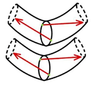
Chart 1. Drawing scheme of the thoracic laminas and screws trajectory. Green dots: entry points at spinolaminar angle, red arrows: screws directions, almost horizontal for the rostral screw and ascending for the caudal screws.
2.1. Case 1
81 years old skinny man with C6 - C7 transdiscal fracture type C AO. He comes 3
months after the initial trauma. He was selected for circumferential cervicothoracic arthrodesis with interbody mesh C6 - C7 and anterior plate with cemented screws and posterior fixation C5, C6 transpedicular screws C7, Th1, Th2 intralaminar crossed screws and cross link (Figure 1(C), Figure 1(D)) associated with posterior decompression (flavectomy C6 - C7).
CT scan (Figure 1(A)) and MRI (Figure 1(B)) confirmed a transdiscal fracture with reabsorption of fracture margins.
In post-operative, he developed wound dehiscence which was treated with resection of spinous apophysis in the cervicodorsal region in order to release tissues tension and vacuum-assisted closure. Followed up more than 2 years. Serial CT demonstrates signs of fusion, noticed a very thin skin above posterior instrumentation (Figure 1(E)).
2.2. Case 2
76 years old man with type B1 AO fracture at C7 level confirmed on CT and MRI (Figure 2(A), Figure 1(B)). The patient presented bilateral distal weakness of hands. The surgery performed was: C6 - C7 anterior arthrodesis with mesh, plate and cemented screws, posterior fixation C4 - C6 lateral mass and C7 unilateral intralaminar screw, Th1, Th2 crossed intralaminar screws and cross link (Figure 2(C), Figure 2(D)). In the postoperative period, showed slow improvement of hand dexterity. Half a year after surgery, X-Ray showed good positioning of the construct (Figure 2(E)).
2.3. Case 3
78 years old man with fracture type C AO C6 - C7 and posterior compression of the spinal cord with ligament fragments on MRI (Figure 3(A)). He was operated as follows: anterior arthrodesis C6 - C7 with cage with screws and plate with cemented crews and posterior fixation lateral mass C4 - C6 and crossed intralaminar screws C7, Th1, Th2 and cross link. Postoperative CT scan showed adequate positioning of the screws (Figure 3(B)).
![]() (A)
(A)![]() (B)
(B)
Figure 3. (A) MRI fracture type C AO C6 - C7 and posterior compression of the spine cord with ligament fragments; (B) postoperative CT scan arthrodesis C6 - C7 with cage with screws and plate with cemented crews and posterior fixation lateral mass C4 - C6 and crossed intralaminar screws C7, Th1, Th2 and cross link, adequate positioning of the screws.
2.4. Case 4
77 years old man with type B3 AO C6 - C7 fracture (Figure 4(A)) was selected for posterior fixation: lateral mass C5, C6 and crossed intralaminar screws C7, Th1, Th2 (Figure 4(B) and Figure 4(C)) with good postoperative evolution and good postoperative CT scan.
![]() (A)
(A)![]() (B)
(B)![]() (C)
(C)
Figure 4. (A) B3 AO C6 - C7 fracture; (B) postoperative CT scan: lateral mass C5, C6 and crossed intralaminar screws C7, Th1, Th2; (C) postoperative CT scan: lateral mass C5, C6 and crossed intralaminar screws C7, Th1, Th2.
2.5. Case 5
31 years old obese, pregnant woman (6 weeks of pregnancy) with fracture type A2 AO Th8 and type A1 AO Th9 (Figure 5(A)) was proposed for Th5 - Th11 with intralaminar crossed screws using crossed intralaminar screws as salvage technique in order to avoid X-Ray due to the pregnancy (Figure 5(B)). Unfortunately, one month after being discharged, she had a spontaneous abortion, postoperative X-Ray showed good screw positioning (Figure 5(C)).
![]() (A)
(A)![]() (B)
(B)![]() (C)
(C)
Figure 5. (A) MRI fracture type A2 AO Th8 and type A1 AO Th9; (B) intra-operative view; (C) postoperative X-Ray after spontaneous abortion.
2.6. Case 6
64 years old patient with Hangman fracture C2 and Th3, Th4 fracture type B2 AO (Figure 6(A), Figure 6(B)) was operated as follows: C2 Hangman fracture fixation with bilateral transpedicular compressive screws and T1 - Th5 crossed intralaminar screws (Figure 6(C)). On postoperative CT scan all the screws are intralaminar, acceptable ligamentotaxis effect of the fixation (Figure 6(D)).
2.7. Case 7
64 years old man, operated before L2 - S1 arthrodesis and interbody cages in another service for multiple level lumbar stenosis, came due to pain and inferior paraparesis with adjacent level fracture L1 and regional kyphosis (Figure 7(A)). He was operated as follows: extension of the fixation to S2 and Th10 (Figure 7(A)) with good restoration of kyphosis. The patient recovered well, but 6 months later came back with severe paraparesis and Th10 screws pull out and regional kyphosis (Figure 7(B)). He was submitted to extension of the fixation to Th3 with crossed intralaminar screws in Th4 - Th8, in Th9 and Th3 we put transpedicular screws with double heads and double lateral rods (Figure 7(C), Figure 7(D)). In the postoperative period, showed slow recuperation of motor deficit, no mention of pain.
2.8. Case 8
64 years old female, operated 12 years ago in another hospital. According to her, she had been operated three times during the hospitalization and does not know the specific pathology that had caused the hospitalization and the surgeries. Medical records were lost. Suffered poliomyelitis in child with severe neurologic sequels. At neurologic evaluation she had severe spastic tetra paresis, disabled and needs constant help, unable to walk on her own (Nurick grade 5). X-Ray reveals iatrogenic kyphosis, listesis C7, lower screws placed intradiscal (Figure 8(A)). MRI and CT scan revealed kyphosis with severe spinal cord compression (Figure 8(B), Figure 8(C)), caused by postoperative pseudarthrosis. She was operated on: cervicothoracic posterior fixation, lateral mass in the cervical region and crossed intralaminar screws in the thoracic region, decompressive laminectomy. In the postoperative period developed right C5 root palsy with gradual recuperation, good arthrodesis material positioning at on CT scan (Figure 8(D)).
2.9. Case 9
82 years old man, fall from height with AO type C dorsal fracture at Th3 level (Figure 9(A)) without neurological deficit. Was operated on: posterior fixation C7 - Th2, Th4 - Th6, Th3 laminectomy (Figure 9(B)). After putting the lateral bars, we performed slight distraction and extension using in situ lateral bar moulding tools with good ligamentotaxis effect, proven on postoperative CT and MRI (Figure 9(C)).
![]() (A)
(A)![]() (B)
(B)![]() (C)
(C)
Figure 9. (A) Sagittal CT scan showing C type Th3 fracture; (B) postoperative CT scan picture; (C) post-op MRI.
2.10. Case 10
82 years old man, admitted for inferior paraparesis with installation within several weeks, no fever. MRI revealed spondylodiscitis Th3 - Th4 with extensive epidural abscess and severe spinal cord compression (Figure 10(A)). He was operated on: corpectomy Th3, Th4 through right side costotranseversectomy and arthrodesis with cylinder and posterior fixation with intralaminar crossed screws two level above and two below (Figure 10(B)). Bacteriologic study showed no bacterial grow.
![]() (A)
(A)![]() (B)
(B)
Figure 10. (A) MRI revealed spondylodiscitis Th3 - Th4 with extensive epidural abscess and severe spinal cord compression; (B) post-op CT scan: corpectomy Th3, Th4 through right side costotranseversectomy and arthrodesis with cylinder and posterior fixation with intralaminar crossed screws two level above and two below.
Discussion: There are plenty of studies describing the feasibility of the C7 laminar screws. Most of the cadaveric study specimens demonstrate that:
1) Diameter of the lamina in C7 is suitable for 3.5 mm screw [7] ;
2) Equivalent pullout strength of C7 laminar screws and C7 pedicle screws, both being superior to lateral mass fixation [8] ;
3) Unilateral fixation is more feasible in women and bilateral fixation in men [9] [10] ;
4) The majority of C7 levels would accept laminar screws based on width; all would accept bilateral screws based on height; and pullout strength was equivalent to C7 pedicle screws and greater than C2 laminar screw fixation [11] [12] .
Tae-Hyun Baek et al. based C7 vertebrae from 18 adult specimens performed morphometric measurements of laminar thickness, and found these anatomic measuments:
- the mean mid-laminar height was 13.7 mm,
- mean minimal laminar thickness was 6.6 mm,
- mean maximal screw length was 24.6 mm,
- mean spinolaminar angle was 50.8 ± 4.7.
Cross-sectional measurement results showed that the mean maximal thickness of upper, middle, and lower thirds was 5.0 mm, 7.5 mm, and 7.3 mm, respectively, and mean surface area for each part was 21.2 mm2, 46.8 mm2, and 34.7 mm2, respectively. The vertical cross-sectioned area of the middle thirds at C7 spinolaminar junction was the largest area and the 3.5 mm screw can be accommodated with 77.8% of feasibility when lower thirds are the screw entry point. Thus, selection of middle and lower thirds for each side of the screw entry point in spinolaminar junction would be the safest way to place bilateral crossing laminar screw within the entire lamina [6] .
Few references exist about the use of intralaminar screws in the thoracic region, except for upper thoracic vertebrae Th1, Th2 in the studies of McGirt [2] and Kretzer [3] . John Weaver et al. analyzed 112 T1 vertebrae. The placement of screws with widths of 3.5 mm or 4 mm and screws with lengths of 24 mm or 26 mm in the T1 lamina was feasible in all of the laminas measured with the exception of 2 outliers. Furthermore, relationships were found between T1 lamina size and patient height and between T1 lamina size and sex, but no relationship was found between T1 lamina size and race. The morphology of the T1 lamina allows for the simple and safe placement of common screw diameters and is a viable salvage or alternative to the traditional pedicle screw [13] . Müller evaluated 50 females and 50 males (age 20 to 60) CT with polytrauma CT from 2010 to 2012, randomly selected. Patients with injury in the thoracic spine, trauma-independent deformity, or dysplasia of the thoracic spine were excluded. A three-dimensional reconstruction of the thoracic spine was performed from the data set. The anatomical data of the lamina were measured under consideration of the potential trajectory of a laminar screw. The caliber of the corresponding pedicle was measured as well. The diameters of the lamina show a decline in superior-inferior direction (0.66 cm in T1 to 0.60 cm in T12 in males, 0.62 to 0.56 cm in females). Diameters of pedicle and lamina show no correlation. Twenty percent of the pedicles have a hypoplasia with a diameter of less than 0.5 cm. However, in these vertebrae, 62.3% of the laminae would be suitable for 0.4 cm lamina screws. Only in 2.75% of the vertebral bodies there was no possibility for intralaminar or pedicle screws. This study shows that it is possible to use intralaminar screws in the thoracic spine in most of the patients [14] .
3. Conclusion
The intralaminar screw insertion in the cervicothoracic junction and in the thoracic level can be used as an alternative or salvage technique to the use of pedicle screws. This technique is relatively safe and easy, but precise anatomic knowledge is required for safe insertion of bilateral crossing intralaminar screws. With a good preoperative planning of screw entry points, collision between the same lamina screw as well as the violation of laminar cortex can be both avoided. For bilateral crossing laminar screw insertion, rostral and caudal spinolaminar junctions can be chosen for each side, respectively, and different angles of screws, almost horizontal for the first screw pointing to inferior angle of lamina and lateral mass and ascendant for the second screw. Preoperative CT analysis helps to understand if the use of crossed screws is a feasible technique for each patient. The use of crossed intralaminar screw in the thoracic region is an underestimated technique; this free hand technique is a fast, efficient and alternative method of transpedicular fixation and this technique at different thoracic levels appears to be a useful tool in the armamentarium of the spinal surgeon. The patients follow up to be published in future articles.