Blur Image Edge to Enhance Zernike Moments for Object Recognition ()
1. Introduction
Zernike moments have been extensively applied and proven successful in the various fields of pattern recognition due to the orthogonality of Zernike basis polynomials providing minimal redundancy [1]. Moreover, the magnitudes of ZMs are not only rotation invariant but also robust to noise. These properties allow ZMs to act the role of shape descriptors suitably [2] [3] such as image retrieval [4]. In palm-print authentication application, computed ZMs serve as a matching utility for each palm-print image [5]. This matching utility uses ZMs’ Euclidean distance of query versus registered sub-images to create a score determining similarities. Used as global features in face recognition, the ZMs are extracted from a face image to reduce the influence of facial expressions, head rotation and image noise [6]. Selecting a maximal ZMs order is crucial for the aforementioned applications due to the fact that the higher maximal order used, the higher recognition rate obtained. Thus, more time is required for data processing.
Since calculating ZMs has been sufficiently researched, the focus shifts to improving the efficiency for such calculations. Due to multiple factorial and trigonometric functions associated with Zernike basis polynomials, calculating ZMs is a complex and extensive process [7]. As higher-order ZMs are calculated, the computation time increases drastically, and the entire ZMs become unreliable as a result of numerical error accumulation. Hence, computing speed and numerical accuracy attract researchers when computing high-order ZMs as they emerge as two research issues. Different recurrence relation was proposed to compute either a single ZM or a whole set of ZMs for the purpose of improving calculation speed [7]. For numerical accuracy, the computation error of high-order ZMs based on q-recursive method was analyzed [8]. The result shows finite precision error being propagated and accumulated during the algorithm process which leads to ZMs instability. Recently, the proposed method of computing ZMs not only provides a fast recursive computation but also yields accurate values of high-order ZMs [9]. This algorithm is adopted in the paper to calculate ZMs due to these reasons.
The main purpose of this paper is to explore the effectiveness of image edge blurring before the ZMs are computed; this issue is rarely examined in the literatures. Therefore, an innovative blurring method on edge pixels was created.
2. Zernike Polynomials and Zernike Moments (ZMs)
Zernike moments are constructed using a set of complex basis polynomials which are a complete orthogonal set defined on the unit disc D. For a complex number  (
( are real numbers,
  represent the polar coordinates and
 ), the Zernike polynomial is given by
 (1)
(1)
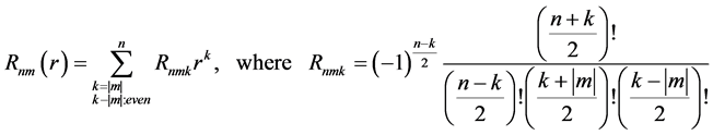
where  is the Zernike radial polynomial,
  is a non-negative integer,
  is an integer satisfying
  an even number and
 . The radial polynomial
  can be expressed as
 (2)
(2)
The Zernike moments  of order n with repetition m can be regarded as the inner product of
  with the Zernike polynomials
 . The Zernike moments
  are defined as
 (3)
(3)
where  is the complex conjugate of
 ![]() and the area differential 2-form is given by
and the area differential 2-form is given by
![]() . (4)
. (4)
Let A denote the image set of size ![]() and A(Z) = {(s,t) Î A | s, t are integers}. The data of the image pixels can be regarded as in a two-dimensional table Px(s,t) for (s,t) Î A(Z) and can be embedded into the unit disc D in the following way. The pixel (s,t) is projected via
and A(Z) = {(s,t) Î A | s, t are integers}. The data of the image pixels can be regarded as in a two-dimensional table Px(s,t) for (s,t) Î A(Z) and can be embedded into the unit disc D in the following way. The pixel (s,t) is projected via ![]() onto the grid centered at
onto the grid centered at
![]() . (5)
. (5)
This results in the corresponding image function ![]() over
over ![]() for which
for which![]() . The discrete form of the Zernike moments in Equation (3) is approximated by
. The discrete form of the Zernike moments in Equation (3) is approximated by
![]() (6)
(6)
With the Zernike moments of an image![]() , this image can be reconstructed by the following formula.
, this image can be reconstructed by the following formula.
![]() (7)
(7)
Then the reconstructed image for a non-negative integer order M can be expressed as
![]() (8)
(8)
In comparison, the difference between these two images can be measured by the mean absolute error (MAE) expressed in Equation (9)
![]() (9)
(9)
A stable and fast computation of high-order Zernike moments using a recursive method was proposed in [10]. Such method is applied to calculate Zernike moments in this paper.
3. Reconstruction Error Distribution
3.1. Artificial Image for Analysis
Two pattern types of images ![]() are created with the use of Equation (10) and (11)
are created with the use of Equation (10) and (11)
![]() (10)
(10)
![]() (11)
(11)
where l = 0 and h = 255. Two testing images of N ´ N pixels, as shown in Figure 1 (N = 256), are used to demonstrate the error distribution between reconstructed image and original image.
By using Sobel edge detector, the edges of 3-stripe image can be identified at (84, y), (85, y) (170, y) and (171, y) for all y.
3.2. Reconstruction Error Analysis
Table 1 shows the reconstructed images and the corresponding normalized error image of the 3-stripe image with different maximal orders. The mean and the standard deviation
![]()
Table 1. The constructed image and error image with different orders.
of the reconstruction error for each stripe are calculated and displayed at the bottom of the second row in the table. L, R and M represent left, right and middle stripe of the image respectively, and thetwo values in a parenthesesrepresent the mean and standard deviation of the corresponding error. These values diminish when the maximal order enlarges. One can observe that the error on edges is more pronounced than other areas at different order in the error image.
As the maximal order = 300, the reconstruction errors of two type images are collected at y = 128 and illustrated in Figure 2. From the figure, the value of error increases when the value of x approaches the edge. The same phenomenon occurs for the error on the right edge of the two-stripe image. This phenomenon is the result of the intensity value being 255 for the left stripe on the two-stripe image. That is a kind of white and black boundary. Hence, only the odd number of stripes in an image is used to demonstrate in the rest of this paper.
In the case of 3-stripe image, the reconstruction errors evaluated at Y = 128 are illustrated with different orders in Figure 3. The largest errors occurred on edges where the magnitudes of the image gradient are maximum. It shows the same phenomena in all different ZMs orders. It is worth noting that the reconstruction error dwindles
![]()
Figure 2. A comparison of reconstruction error for 2-stripe and 3-stripe images.
![]()
Figure 3. The reconstruction error with different orders for y = 128.
and the oscillation increases in frequency when the error location approximates the edge with increasing maximal order of ZMs.
This behavior is similar to an approximated square wave which is represented by a summation of orthogonal basis polynomials. The approximation of the function by a finite number of basis polynomials can exhibit overshoot, undershoot and ringing. By using more terms in the approximated function, less distinct errors are produced in said function. The overshoot at a jump discontinuity does not fade out as more polynomial terms are added to the sum, also known as the Gibbs phenomenon [10].
As stated in previous section, Zernike moments have been widely applied in the field of pattern recognition. For shape matching or identification, Zernike moments are used as invariant descriptors. In the following, we propose our method to raise the effectiveness of using Zernike moments as shape descriptor. Using the 3-stripe image as an example, the blurring procedure is taken first by replacing the intensities of pixels at x = 84, x = 85, x = 170 and x = 171 by some values different from 0 and 255 with the assumption that the original intensity of pixels on (84, y) and (85, y) for all y are l and h respectively. After the blurring process, corresponding new intensities of pixels are replaced by (h − l)/3+l and (h − l) × 2/3 + l. A similar procedure is applied to pixels on (170, y) and (171, y) for all y. Two and four consecutive pixels blurring methods are shown in Figure 4.
The comparison between absolute reconstruction error at maximal order = 300 of two-pixel blurred image and blurless image is presented in Figure 5. This result shows that errors are increased at x = 84, 85, 170 and 171 but decreased in other places.
Let ADi, as shown in Equation (12), be the improvement of the mean absolute error of the image which is blurred by the proposed method.
![]()
Figure 4. Two approaches to blur the boundary.
![]()
Figure 5. The comparison of absolute reconstruction errors for 2-pixel blurred and blurless images for the case of (0, 255, 0).
![]() (12)
(12)
where ![]() is the mean absolute error of the i-pixel blurred image. In the paper, 2-pixel and 4-pixel blurring approaches are simulated.
is the mean absolute error of the i-pixel blurred image. In the paper, 2-pixel and 4-pixel blurring approaches are simulated.
3.3. Performance of ADi
In this section, two experiments are implemented to evaluate the performance of ADi. The difference of intensities on two adjacent stripes is investigated in the first experiment. The second experiment examines the influence of different number of stripes in an image on ADi.
3.3.1. ADi vs. Different Intensity in Stripes
The intensity difference on two adjacent stripes abates in the succession of images as shown in Figure 6. The 3-tuple within parentheses denotes the gray intensity of each stripe in the image.
The reconstruction errors of these images by the proposed edge blurring methods with different maximal order are calculated. The ADi results are displayed in Figure 7. In the legend, (0, 255)-2 denotes that the 2-pixel blurring method is applied in the 3- stripe image whose intensities are 0 and 255 in the adjacent stripes, whereas (0, 255)-4 denotes that the 4-pixel blurring method is applied in the 3-stripe image whose intensities are 0 and 255 in the adjacent stripes.
With the maximal order of 300, the value of ADi is superior to other orders when the image is 2-pixel blurred. The value of ADi acquired become less prominent with smaller differences in intensities on adjacent stripes.
3.3.2. ADi vs. Different Number Stripes
In order to better understand the effect of image stripe numbers on ADi, a series of images which have different number of equal width stripes are created as shown in Figure 8. The width of a stripe, distance between two edges, is denoted as Di with i being the
![]()
Figure 6. Different intensities in stripes.
![]()
Figure 7. The comparison of ADi for blurred and blurless images with different orders.
![]()
Figure 8. A series of images with a different number of stripes.
number of stripes in the image. For reference, D3 is about 85 pixels and D31, the largest number of stripes in the examination, about 8 pixels.
The 2-pixel blurring method with the maximal order greater than 50 is applied to images as shown in Figure 8. The graph of AD2 with respect to Di is depicted in Figure 10. When Di is larger than 15, AD2 has the most improvement with applying maximal order = 300. However, this is not the case when Di is small.
By further analyzing the error of experiment in Figure 9, the pixels are partitioned into two groups which are edge pixel group and non-edge pixel group. The MAE is calculated with maximal order = 300 for each group separately. The results are shown in Figure 10.
The ratio of MAE for edge pixel group to MAE for non-edge group is drawn in Figure 11. The figure has a clear indication that 2-pixel blurring method provides a much more centralized edge reconstruction error and error reduction in different places than 4-pixel approach for all Di.
![]()
Figure 10. Di vs. MAE for edge pixel and non-edge pixel groups.
![]()
Figure 11. Di vs. the ratio of the MAE of edge pixels to the MAE of non-edge pixels.
As presented in previous sections, Zernike moments are widely used as the shape descriptors in many image applications. Intuitively, the contour information of a shape is the most valuable feature. To extract this valuable information, the proposed method blurs edge pixels and calculates Zernike moments. Using these results, the characteristic of emphasizing information on edges and deemphasizing non edges are obtained thus providing the contour information of a shape.
4. Template Matching
The purpose of this experiment is to demonstrate the effectiveness of template matching via our purposed method. Two real scene images were taken with camera rotation through different position. Different scale images were constructed to detect local extremea [11] for these two images. These local extrema, depicted by red dots in Figure 12, are considered as keypoints. Then, the ZMs is calculated around each keypoint to represent its own local feature.
4.1. Feature Extraction
The local circular image, with a radius of 20 pixels, surrounding a keypoint is extracted. Then, ZMs with order = 25 are calculated for all circular images. Due to the rotation invariant, the magnitudes of the computed ZMs are taken to serve the feature of a keypoint. In this study, blurring on the edges of an image is considered before taking ZMs. For that purpose, Sobel operator is applied to locate the possible edges on these two images. The corresponding resultant gradient images are shown in Figure 13.
The top 10% greatest gradient magnitudes of pixels in a circular image are treated as
![]()
![]() 60 detected keypoints 71 detected keypoints
60 detected keypoints 71 detected keypoints
Figure 12. Two images taken with a rotation of the camera, detected keypoints in red.
![]()
![]()
Figure 13. Two gradient images of images in Figure 12.
edge pixels. In blurring edge process, the intensity value of edge pixel is replaced by the average intensity value of its 8-connected pixels. The comparison of two images, with and without blurring edge pixel, is shown in Figure 14.
4.2. Keypoint Matching
The Euclidean distance is used to measure the similarity between keypoints on two images. In order to eliminate unreliable matching pair, the keypoint matching must comply with the following criterion:
For a certain keypoint, the distance of the second most similar keypoint (D1) divided by the distance of the most similar keypoint (D2) must be less than the given threshold.
Given different thresholds, the number of matched keypoint pairs between two images are shown in Table 2. The matched pairs for threshold = 0.6 are drawn in Figure 15.
![]()
![]()
![]() (a) (b) (c)
(a) (b) (c)
Figure 14. (a) The circular image around a keypoint; (b) Edge points in red color; (c) The circular image after edge pixels blurred.
![]()
![]() (a) (b)
(a) (b)
Figure 15. The comparison of matched pairs between blurless image and blurred image. (a) 29 matched pairs; (b) 29 matched pairs.
![]()
Table 2. The number of matched keypoint pairs at different thresholds, the number in paren- theses for the case of ∞ denoting wrong matched pairs.
In Figure 15(b), six more keypoint pairs in purple line are matched and one pair in green line fail to match when the edge pixels were blurred. From the results, the blurring edge procedure enhances the ZMs for template matching even when the order of ZMs is 25.
5. Conclusion
This study presents a novel image edge blurring process before evaluating the Zernike moments. The experimental results indicate that Zernike moments with the edge blurring of image can perform better than blurless images. In order to make prominent characteristic of the blurring edge with high-order ZMs, we will further investigate the proposed method on popular image databases in future work, especially in the issue of shape identification.
Acknowledgements
This work was supported by Ministry of Science and Technology, Taiwan, under research project number MOST 105-2221-E-231-013.