1. Introduction
The motion transmitted by a machine to both a tool and a work piece being shaped, can be expressed by means of the fundamental kinematic cutting schemes [1] [2] [3] [4] . As per the conventional fundamental kinematic cutting scheme, the movement of cutting elements of the tool relative to the surfaces of the work piece being cut follows a path relative to working motion at speeds, predetermined by relations: the tool (T)-the work piece (D).
When cutting the work pieces of any form in the simplest and shortest way, possible the kinematics of cutting are represented as a combination of two basic motions: linear (straight line) and rotary. In this case, both can be either primary or feeding, which is factored into different classifications of fundamental kinematic cutting schemes for cutting simple and complex shapes [1] [2] [5] [6] [7] [8] .
According to DIN 6580 [2] , cutting motion is the relative movement of the work- piece and the tool, which would perform only a single chip removal per a rotation or a stroke without the feeding motion, where the direction of the cutting motion at any given moment is called the cutting direction, and the cutting speed V is the instantaneous velocity of the selected point of the cutting edge in the cutting direction. Feed motion S is the relative movement of the work piece and the tool, which, combined with the cutting motion, allows repeated or continuous chip removal during a certain number of rotations or strokes. The feed rate U is the instantaneous velocity of the tool along the feeding direction.
When contouring the formed work-pieces, such as turbine blades, air and marine propellers, etc., as well as during cutting of toothed work-pieces with different gearing, multiple linear and rotary motions and various methods for their description [9] [10] [11] are used.
2. The History and Analysis of Previously Performed Studies
The first genetic information on the kinematics of cutting refers to the Stone Age, when early human used a wooden stick (the prototype of the future machine spindle and a cylindrical tool), setting it into an alternating rotary motion by a handle or bow drive [12] [13] [14] . During repeated attempts to make fire, the early human noticed a notch in the rock (the prototype of the work piece), where the end of the wooden stick (the prototype of the rotating tool) rubbed against it, which inspired the future design of vertical drilling machine for drilling holes in a work piece (Figure 1(a)).
Having learned how to make fire, the early human began to cook on it, turning the stick with the game (the prototype of the rotating work-piece) by hand with a lever, which would later inspire designs of a turning lathe (Figure 1(b)) for wood and a cylindrical grinding machine (Figure 1(c)) with a rotating stone disc for tool or weapon sharpening or grinding.
With the advent of machines and as they evolved, especially since the use of electricity, machine kinematics and fundamental kinematic cutting schemes got more complicated
![]() (a) (b) (c)
(a) (b) (c)
Figure 1.Prototypes of vertical drilling (a), lathe (b) and cylindrical grinding (с) machines with simplified kinematics of cutting: 1―work piece (product); 2―tool; 3―support system; 4―spindle; 5―main motion drive; n―rotations (double strokes); S―feeds.
and diversified that required further theoretical research, generalization and classification.
An extensive, but incompletely systematized and incomprehensive classification of the fundamental kinematic cutting schemes was offered by Granovsky G. I. [1] with the numeric three-digit code, conventional kinematic scheme representation in Cartesian reference system and conventional path representation at the contact point of the tool and work-piece (Table 1). The first digit of the classification code indicates the number and the type of motions: 1)―one linear; 2)―two linear; 3)―one rotary; 4)―one rotary and one linear; 5)―two rotary; 6)―two linear and one rotary; 7)―two rotary and one
![]()
Table 1. Some kinematic cutting schemes (classification detail).
linear; 8)―three rotary.
This classification is used for describing and synthesizing machines configurations, built primarily using modularization with the analysis and transformation of the structural formulas.
With the use of computers, the mathematical models of kinematic cutting scheme were widely introduced [15] [16] enabling analysis of various options so that the best of them meeting given quality criteria are chosen.
The well-known classification of the kinematic shaping schemes is only arranged according to the first feature, i.e., the number of affine transformations [11] . The number of affine transformations is three. Three rotations and three linear movements can be carried out here. The idea is, however, to justify and determine the necessary and sufficient number of affine transformations in the kinematic scheme, as well as to establish the particular motions in each reference point and the particular relative arrangement of the neighbouring reference points. This is carried out in order to determine an existence range of the composite kinematic shaping schemes concerning the gear tooth systems of different classes, types and kinds, as well as to work out a unified mathematical model, systematization and detailed classification of the kinematic shaping schemes. A solid body has six degrees of freedom. If all possible mobilities of the shaping member and the member to be shaped are taken into account, six affine transformations are sufficient in the composite kinematic scheme of the gear tooth system. This determines all existing kinematic shaping schemes of different classes, types and kinds.
In the fundamental paper [10] with regard to the processing of gears, the generalized mathematical model of kinematic shaping schemes, which can be described by 4th- order matrices as follows:
 (1)
(1)
where ―matrix of moving equation of shaper link (T) that is specified in 1. coordinate system relative of fixed part link (P),
 ―matrix of location, i.e., matrix of coordinate transformation by conversion from i-th to i + 1-th reference point,
 ― matrix of shaper link moving in the i-th reference point,
 ―matrix equation of shaper link surface in the 1. reference point,
  , independent parameters of shaper link, I―number of reference point, A, B―starting and finite indices.
This work introduces an example of the synthesis and optimization of the gear shaping machine configuration according to the accuracy and stiffness criterion and the grid schematic [2] - [25] .
3. New Trends in Machining
In recent years, the development in the field of manufacturing systems design has started gravitating towards the gradual transition to structural-system studies [24] . Based on the progress in biology, cybernetics, mechatronics, information technology, synergy, socionics, artificial neural networks, psychology and other cognitive sciences, new interdisciplinary research areas are emerging. The prime example of those is genetics, which studies the heredity laws and structural variability of evolving natural and anthropogenic systems [17] [18] [19] [20] [26] .
The methodology for generalization and synthesis of the knowledge in the fundamental sciences is based on the principles of a limited number of elementary generic structures with the introduction of the gene concept (a moving charge as an electromagnetic one, a material point as a mechanical one) [21] .
The material point is proposed as a mechanical gene―the material object carrying hereditary information in mechanical systems (Figure 2), fixed in static anthropogenic systems and moving in space under the action of the force F and (or) the moment M in dynamic anthropogenic systems [22] .
In [21] , the genetic bases for formation of surfaces from a position of kinematical way of their forming have been considered as a systematic-morphological approach is used [23] . The morphological matrix including the determining of surface and the forming of various forms has been reduced.
It is proposed, that transfer of force, movement and energy in space during imaginary experiment is represented as a generalized model of kinematic, power and energy transfer from a material point at the entrance to the Cartesian coordinate system X1Y1Z1 to another material point at the exit of the coordinate system X2Y2Z2. This gives 144 variants of elementary flows (parental chromosomes), that become more complicated during the process of genetic development, forming a combinatorial group of
![]()
Figure 2. Mechanical gene―moving material point (a) in Cartesian reference system XYZ (b).
chromosomes descending from n-generation, using five universal genetic operators of synthesis: replication, crossing, inversion, crossover and mutation [19] . Advantages of the genetic and morphological approach are illustrated with the examples of new clamping mechanisms and designs for new generation of machines, including those with the parallel structure mechanisms which will be used in the modelling of cutting kinematics in this article [17] [18] [21] .
4. Essence of Genetic-Morphological Approach
Cutting process can be represented as two contacting and interacting material points (Figure 3(a))―the work-piece (O1) and the tool (O2), wherein each of them is performing linear and rotary motions within their own coordinate system X1Y1Z1 and X2Y2Z2 (Figure 3(b)).
As indicated on Figure 3(b), the material point ω(x1, y1, z1) O1 during primary rotary motion, with account for feed linear motion S(x1, y1, z1) and coordinate radius R(x1, y1, z1), can be described by the set
 . (2)
. (2)
Similarly, the material point O2 can be described
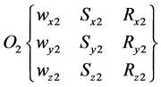 . (3)
. (3)
The interaction of these points O1 and O2 (Figure 3(a)) as a convolute morphological model at the chromosomal level [16] [17]
![]()
Figure 3. A generalized model of interaction between the work-piece and the tool (a) and the proposed 3D kinematic cutting scheme in the form of two material points O1 and O2 in the Cartesian coordinate system (b).
 . (4)
. (4)
Provided no rotary or linear motion is present and points are positioned along the geometric axis of the machine as an alternative to implementation of feature in morphological model a 0 (zero) value, the explicit morphological model of kinematic cutting scheme of a work-piece O1 by a tool O2 may be represented as follows:
 (5)
(5)
The total number of variants of kinematic cutting schemes [22] :
 (6)
(6)
where: N01 is a set of parent chromosomes of work piece motions (material point O1); N02 is parent chromosomes tool motions multiplier (material point O2).
Among these kinematic schemes, there are non-implementable combinations (chromosomes), where there is no motion, for example:
 ;
;

With the known decision-making methods under the specified criteria [16] , the best options for further implementation are chosen.
It should be noted that the number of kinematic cutting scheme variants increases significantly in case of multi tool machining of a work piece (when there are two or more material points O2) and multi tool multi position machining of several work pieces (when there are two or more material points O2 and O1), which is the subject for further research.
5. Examples of Genetic-Morphological Approach at Modelling of Various Kinematical of Cutting
For illustrative purposes, Figure 4 represents some basic kinematic cutting schemes, recorded on a chromosomal level in the form of structural genetic formulas using the genetic-morphological approach [17] [18] [19] from the morphological model (5).
Figure 4(a) shows a kinematic cutting scheme described by a numerical code 101 [1] without specifying the type of machining. The use of genetic-morphological approach helps obtain specific types of machining in the form of the genetic code at the chromosomal level:
(0,  , 0) - (0, 0, 0)―axial pull of the moving work piece (point O1) with the fixed tool position (point O2);
(0, 0, 0) - (0, ![]() , 0)―axial pull of the fixed work piece (point O1) by moving along the axis Х1 tool (point O2).
, 0)―axial pull of the fixed work piece (point O1) by moving along the axis Х1 tool (point O2).
Figure 4(c) represents the kinematic cutting schemes with numeric code 401 [1] , which for specific machining schemes can be recorded in the form of variants of the genetic code at the chromosomal level:
( ![]() , 0, 0) - (0,
, 0, 0) - (0, ![]() , 0)―axial drilling of the rotating work piece (point O1) by a drilling tool (point O2), which does not rotate, but linearly moves along the axis Х1;
, 0)―axial drilling of the rotating work piece (point O1) by a drilling tool (point O2), which does not rotate, but linearly moves along the axis Х1;
(0, 0, 0) - (![]() ,
, ![]() , 0)―axial drilling of the work piece (point O1) not being rotated by a rotating, linearly moving along the axis Х1 drilling tool (point O2);
, 0)―axial drilling of the work piece (point O1) not being rotated by a rotating, linearly moving along the axis Х1 drilling tool (point O2);
![]()
Figure 4. Variants of kinematic cutting schemes, synthesized using the genetic-morphological approach.
(0, ![]() , 0) - (
, 0) - (![]() , 0, 0)―axial drilling of the linearly moving work piece (point O1) by rotating coaxial tool (point O2);
, 0, 0)―axial drilling of the linearly moving work piece (point O1) by rotating coaxial tool (point O2);
( ![]() ,
, ![]() , 0) - (0, 0, 0)―axial drilling of the rotating and linearly moving work piece (point O1) by fixed tool (point O2).
, 0) - (0, 0, 0)―axial drilling of the rotating and linearly moving work piece (point O1) by fixed tool (point O2).
Figure 4(c) and Figure 4(d) present kinematic cutting schemes with numeric code 401 [1] , that are differ from each other by genetic code at chromosomal level:
( ![]() , 0, 0) - (0,
, 0, 0) - (0, ![]() ,
,![]() )―longitudinal lathe turning of rotating work piece (point O1) by linearly moving tool, which is the straight-turning tool (point O2) on the distance of radius
)―longitudinal lathe turning of rotating work piece (point O1) by linearly moving tool, which is the straight-turning tool (point O2) on the distance of radius ![]() (Figure 4(с));
(Figure 4(с));
(![]() ,
, ![]() , 0) - (0, 0,
, 0) - (0, 0, ![]() )―longitudinal lathe turning of a rotating work piece (point O1) linearly moving along the axis by a straight-turning tool (point O2), which is hard mounted at distance Rz (Figure 4(d)), that is typical for sliding-head type automatic lathes [2] .
)―longitudinal lathe turning of a rotating work piece (point O1) linearly moving along the axis by a straight-turning tool (point O2), which is hard mounted at distance Rz (Figure 4(d)), that is typical for sliding-head type automatic lathes [2] .
6. Conclusion
The simple examples of modelling and synthesis of kinematic cutting schemes given in this publication are proving the efficiency and viability of genetic and morphological approach suggested by Kuznetcov. Iu. N., professor of the National Technical University of Ukraine. As the basis of the genetic approach, the material point, which can interact with other material points in space and time, simulating anthropogenic systems of different origin, is introduced as a material object carrying the hereditary information.
Acknowledgments
The Author thanks the editor and the referee for their comments.